Sase PDG 3000 User manual

PDG 3000
230V / 460V
PLANETARY
EDGER
SASE Company, Inc.
Phone 800.522.2606 or Fax
877.762.0748
www.SASECompany.com Version 2.0
01/01/2020


Congratulations on your decision to get the Power of SASE behind you! SASE is committed to excellence, excellence
in the quality of products we sell and excellence in service and support aer the sale. It is important to us that your
business continues to succeed and grow, and we know that the right products, service and support can have a great
impact on your bottom line.
SASE has made great strides in the concrete preparation and polishing industry over the years. With a 40,000 square
foot distribution and service facility in Seattle, a 22,000 square foot distribution and service facility in Knoxville, and
local sales and technical support representatives throughout the United States, SASE is able to provide unsurpassed
service and technical support for the contractor.
At SASE we engineer and manufacture our own equipment, which allows us to be in control of the quality of the
equipment we sell. SASE oers a complete line of concrete preparation and polishing equipment, our newest intro-
duction being our new line of PDG planetary diamond grinders, which is setting a new standard for the concrete
grinding and polishing industry. SASE is also the leader in diamond tooling technology.
We look forward to a long and prosperous partnership with you! ank you again for choosing SASE. You won’t re-
gret having the Power of SASE behind your company!
Sincerely,
SASE Company, Inc.
Jim Weder
President
Corporate Oce Details
26423 79th Ave South
Kent, WA 98032-7321
1.800.522.2606 (P)
1.877.762.0748 (F)
www.SASECompany.com
sales@SASECompany.com


Introduction
The SASE PDG 3000 planetary diamond grinder is designed to grind edges and
under toe kicks. Their applications range from rough grinding through to a
polished finish.
It is extremely important all users be familiar with the contents of this manual
before commencing operation of either machine. Failure to do so may result in
damage to machinery or expose operator to unnecessary dangers.
IMPORTANT
Only staff that has received the necessary training, both practically and
theoretically concerning their usage should operate the machinery.
Mechanical Action of Moving Machine Parts
Several parts of this machine are understood to be dangerous.
The Grind Head has a rotation and a counter rotation, keep body parts clear of
the moving grinder head.
The handle is heavy. Failure to lock the handle in place can result in operator
injury.
During operation, the machine has a twisting force. If you lose control of the
machine, it will walk away without you. The operator has to maintain control of
the machine. The machine moving freely can damage finished floor sections, or
wall sections. Not to mention anyone caught by the grind head could be
seriously injured.
Preventative Maintenance
Preventing the hazard is the best case scenario. Preventative Maintenance (PM)
is the responsibility of the operator.
Check and clean air filter regularly(200 operating hours)
Keep a Log Book for all service done.
Be sure that adequate vacuum system is in use.
Be aware of changes in operation, smell, noise, etc. while operating
Report to management ANY safety concerns.
Follow manufacturer recommendations for all motor maintenance.
Storage
The machine should always be stored in a cool, dry location. Moisture may upset
fragile electrical components.
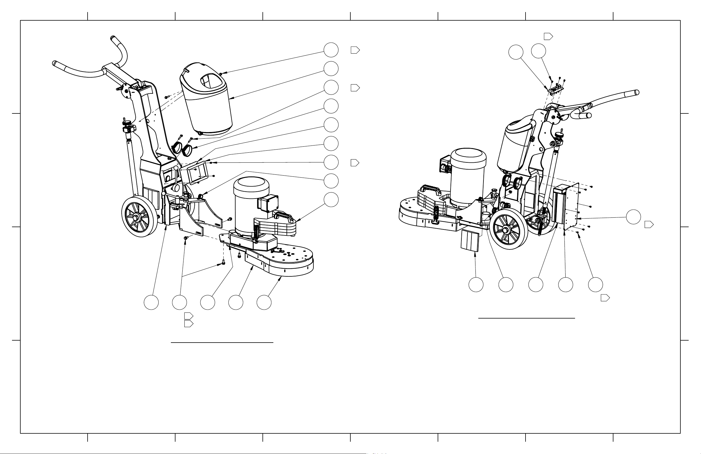
Break-Down
The machine can be divided into two main parts.
1. Chassis/Frame section –This comprises the handle bars, body
panels, Steel frame and wheel assembly.
2. Drum/Head –this comprises the motor, cover,
grinding/satellite/ planetary heads and internal components
The machine has been manufactured to allow movement between the chassis
and head via the connection point. This movement is important during the
grinding process as it creates a “floating” effect for the head. The floating gives
the head a self leveling effect, negating the need to adjust the height of the
head as the machine passes over floor areas with different slopes or
undulations.
Set-Up
Position the grinder in the working area. Make sure there are diamonds
underneath the machine, and that the head locks are tight.
IMPORTANT
Planetary head and grinding heads are set to turn in opposite directions of each
other.(as shown in this depiction)
When using the machine, each grinding head must always have the
same diamond type and number of diamonds as the other heads.
Each diamond must also be the same height as the next.
The skirt must be adjusted so that a good seal is established, between
the floor and the grind head.
When setting the height of the handle, the operator is the guide. The comfort of
the operator during grinding is key. The handlebar should rest right at the
operator’s hip bone. When the machine is running, there will be a grinding force
to one side that can be felt through the handlebars. Use the hip to resist this
force instead of the arms.
Control Panel
The control panel consists of 2 switches, a knob,and a button.
SPEED Controls the speed of rotation and counter rotation
simultaneously. Range: Low 0to High 10
RIGHT Switch controls rotation of the drum in the 'forward' direction.
*Will not work if inverter is in fault
LEFT Switch controls rotation of the drum in the 'reverse' direction.
*Will not work if inverter is in fault
START/RESET Button push sends a reset signal.
To start the first time, the machine requires a reset signal.
To start after a fault, the machine requires a reset signal.
RUN Turn switch to run, to get rotation to start.
*Will not work if inverter is in fault
STOP Turn switch to stop, to get rotation to stop. If the machine
faults during operation, turn the dial to stop before reseting.
This switch has a 'null' position, in the middle. Acting as a stop. Giving
neither forward or reverse direction.
*RESET*
Turn the stop/run switch to the STOP position to prevent uncontrolled start at reset

Determining Diamond Selection
Proper diamond selection is one of the most important step in creating the
perfect floor finish.
Diamond Background
Diamond abrasives usually consist of 2 components:
Diamond powder (also known as diamond crystals or grit). By
changing the size of the diamond powder or grit, we can change how
coarse or fine the scratches will be that are left behind from the
grinding process.
A binding agent (metal or resin). Diamond powder is mixed and
suspended in either a metal or resin binding agent. When suspended
in a metal bond matrix, the finished product is referred to as a Metal
Bond or Sintered diamond segment. When suspended in a resin bond
matrix, the finished product is referred to as a Resin Bond diamond
segment or pad.
General Diamond Principles
Diamond Grit Size:
Changing the size of the diamond grit to a smaller particle/ grit size will affect the
performance of the diamond tool in the following ways:
Create a finer scratch pattern.
Increase the life of the diamond tool.
The opposite will occur when changing to a larger particle/grit size.
The Binding Agent/Metal Bond or Resin Bond:
Increasing hardness of bond will
Increase life of diamond tool.
Decrease production rate.
Cause diamond tool to leave finer scratches in dry –grinding
applications (when compared to a softer bond diamond tool with the
same diamond grit size).
A hard bond matrix should be used on a soft floor and a soft bond
matrix should be used on a hard floor.
Grinding disc set-up:
The set-up of diamond segments on the grinding heads of the machine will
influence the performance of the machine, the productivity levels and also the
finished floor quality.
Changing of Diamonds
Different applications often require different selections of diamond tooling.
There will be many occasions when the grinding discs need to be changed.
Following is a guide for this procedure.
Preparation
Press the Stop button and engage the Emergency Stop button. As an
extra precaution, you can unplug the power cord.
Change
1. Set handle in upright position.
2. Pull back on handle to lift grinding head off the ground (Above Top).
3. Lay machine back on the
ground
4. Put on gloves.
5. Remove grinding disc from
flex plate.
6. Check to ensure that all
discs are secure.
7. Once new diamonds have
been attached, reverse
procedure to lower machine
to ground.
As new diamonds may be a different height than the set being previously used,
re-adjust skirt to ensure good seal is established with the floor.

. Personal Safety
Please read the operator’s manual carefully and make sure you
understand the instructions before using the machine.
WARNING! Dust forms when grinding which can cause injuries if
inhaled. Use an approved breathing mask. Always provide for good
ventilation while machine is in use.
Always wear approved PPE:
Protective helmet Hearing protection
Dust Mask Protective goggles
Non-slip boots with steel toe Protective gloves
WARNING
Under no circumstances may the machine be started without observing the
safety instructions.
Should the user fail to comply with these suggestions, SASE Company Inc. or its
representatives are free from all liability both directly and indirectly.
Read through these instructions and make sure that you understand the contents
before starting to use the machine.
Should you, after reading the safety instructions, still feel uncertain about the
safety risks involved you must not use the machine, please contact your SASE
representative for more information.
Reminder
Always check electrical source before starting.
Only qualified personnel should be allowed to operate machinery.
Never use a machine that is faulty. Carry out the checks, maintenance
and service instructions described in this manual. All repairs not
covered in this manual must be performed by a repairer nominated by
either the manufacturer or distributor.
Always wear personal safety equipment such as sturdy non-slip boots,
ear protection, dust mask and approved eye protection.
Machinery should only be started when grinding heads are resting on
the ground.
The machine should not be started without the dust skirt attached. It
is essential a good seal between floor and machine be established for
safety, especially when operating in dry grinding applications.
When changing the grinding discs ensure the unit is OFF. Press the
Stop button and when the machine is completely stopped, press the
emergency stop button. Disconnect the power cord, to add
protection.
The machine should not be lifted by handles, motor, chassis or other
parts. Transportation of the machine is best done on a pallet / skid to
which the machine must be firmly secured.
Extreme caution must be used when moving machinery by hand on an
inclined plane. Even the slightest slope can cause forces/ momentum
making the machinery impossible to brake manually.
Never use the machine if you are tired, if you have consumed any
alcohol, or if you are taking medication that could affect your vision,
your judgment or your coordination.
Never use a machine that has been modified in any way from its
original specification.
Be on your guard for electrical shocks. Avoid having body contact with
lightning conductors/metal in the ground.

Transportation
The machine comes equipped with an electronic system called a variable speed
drive or a frequency converter. The drive enables the variable speed and
direction component of the motor.
The drive is located in the steel cabinet mounted on the machine chassis. As with
all electronic equipment, the drives are sensitive to excessive vibration, rough
treatment and high levels of dust. Much care and attention has been given by
SASE to ensure maximum protection is given to the drive.
When transporting, it is important to ensure the machinery is properly secured at
all times to eliminate “bouncing”. Ensure the chassis or frame section of the
machine is secured down at all times when in transit.
The machine should always be transported under cover limiting the exposure to
natural elements –in particular rain and snow. The machine should not be lifted
by handle, motor, chassis or other parts.
Transportation of the machine is best done on a pallet/skid to which the machine
must be firmly secured. Do not attempt to slide the tines/forks from a fork lift
under grinding heads unless on a pallet/skid. Failure to do so can cause extreme
damage to grinding heads of machine and internal parts.
Speed
The grinding speed should start low and increase as the operator becomes more
comfortable with the application. Be sure that the RPM’s do not exceed 2000
when starting and stopping the drum rotation. The machine should be running
and the drum rotating before speed selection is fine tuned.
Check that the cord and extension cord are intact and in good
condition.
Never use the machine if the cord is damaged, hand it in to an
authorized service workshop for repair.
Do not use a rolled up extension cord.
Electrical cords must not exceed 200ft in length.
The machine should be connected to an earthed outlet socket.
Check that the mains voltage corresponds with that stated on the
rating plate on the machine.
Ensure the cord is behind you when you start to use the machine so
that the cord will not be damaged.
WARNING - HIGH VOLTAGE!
Inspection and/or maintenance
should be carried out with the
motor switched off and the
plug disconnected.
Safety Hazards
Before using the equipment, inspect electrical lines, and connections. Make sure
the machine is in good working order. Electrical shock from a split wire could be
fatal.


15
4X
14
4X
8
7
3
16
2X
6
21 13 12
16
2X
17
2X
18
EXPLODED FRONT VIEW
3
2
3
4
14
8X
4
5
14
8X
10
2X
11
3X
14
4X
9
EXPLODED REAR VIEW
2
2
2
2
SASE COMPANY, LLC
26423 79TH AVE S, KENT, WA 98032
TITLE:
WEIGHT: 273.4 lbs
SCALE: NONE
SHEET 2 OF 2
PDG 3K FINAL
A A
B B
C C
D D
8
8
7
7
6
6
5
5
4
4
3
3
2
2
1
1
P/N: PDG.33000.00

Item No. Part No. Description Qty.
1
SEE PAGE 12
PDG 3K EDGER FRAME SUBASSEMBLY 1
2
SEE PAGE 18
3K EDGER FRONT END ASSEMBLY 1
3.0
PDG.45059.00 TANK 1
4 PDG.33010.00 PDG 3K EDGER INVERTER COVER 1
5 PDG.30045.00 INVERTER KBVF-45 1
6SEE PAGE 32 PLANETARY EDGER WEIGHT ASSEMBLY 1
7 PDG.33014.00 INVERTER WINDOW 1
8 PDG.33013.00 WINDOW FRAME 1
9 PDG.32100.00 PLANETARY EDGER INSTRUMENT PANEL 1
10 PDG.50120.00 COVER, VENT HOLE 2
11 NB.59.100 90 MALE GRIP CORD 3
12 PDG.32107.00 SHROUD, FORWARD 1
13 PDG.32108.00 SHROUD, REAR 1
14 NB.11.107 SCREW, FLANGED SOCKET HEAD CAP M4-0.7 X 8 ZINC 24
15 NB.11.123 SCREW, FLANGED HEX HEAD CAP M8-1.25 X 20 NON-SERRATED ZINC 4
16 NB.11.112 SCREW, FLANGED HEX HEAD CAP M6-1.0 X 30 NON-SERRATED ZINC 4
17 NB.52.202 CLAMP, LOOP 3/4" WIDE, 2-1/2" 2
18 NB.52.204 CLAMP, LOOP 3/4" ID 1/2" WIDE 1
PDG3000 FINAL
PDG3000 FINAL NOTES
3.1 PDG.32105.00 DECAL, SET 3000 1
3.2 PDG.32104.00 PLUG, WATER FITTINGS 2

7.1 7.2
2X
7.3 12 10
2X
11
7.4
7.5
17
8
3X
16
2X
362.1 15
2X
2.2
2X
5
2X
14
2X
13
9
10
161
2
3
4
4 4
4 4
4
2
SASE COMPANY, LLC
26423 79TH AVE S, KENT, WA 98032
TITLE:
WEIGHT: 81.8 lbs
SCALE: NONE
SHEET 2 OF 2
PDG 3K EDGER FRAME
SUBASSEMBLY
A A
B B
C C
D D
8
8
7
7
6
6
5
5
4
4
3
3
2
2
1
1
P/N: PDG.33001.10

Item No. Part No. Description Qty.
1 PDG.33001.00 PDG 3K EDGER FRAME 1
2
SEE PAGE 12
PDG 3K EDGER TILT PLATE ASSEMBLY 1
2.1 PDG.33002.00 PDG 3K EDGER FRAME TILT PLATE ASSEMBLY 1
2.2 PDG.33023.00 BEARING 6201-2RS 2
3
SEE PAGE 16
PDG 3K EDGER BALL SCREW ASSEMBLY 1
4
PDG.33003.00
PDG 3K EDGER FRAME SWIVEL BRIDGE 1
5 PDG.33011.00 PDG 3K EDGER SWIVEL PIVOT SPACER 2
6
SEE PAGE 14
PDG 3K EDGER WHEEL ASSEMBLY 1
7
SEE PAGE 12
PDG 3K EDGER HANDLEBAR SUBASSEMBLY 1
7.1 PG.33004.00
PDG 3K EDGER HANDLEBAR
1
7.2 PDG.32099.00 IGUS PLASTIC BUSHING 2
7.3 NB.15.255 SCREW, SHOULDER 16MM X 100MM, M12 X 1.75 1
7.4 PDG.32081.00 T-HANDLE QUICK RELEASE PIN W/ LANYARD 1
7.5 NB.20.131 NUT, NYLOC M10 ZINC 1
8 NB.15.253 SCREW, SOCKET HEAD SHOULDER M16 X 20 M12-1.75 3
9 PDG.33022.00 HANDLE, ADJUSTABLE WITH BALL KNOB 1
10 NB.30.154 BRASS FLAT WASHER M12 2
11
PDG.33024.00
HANDLE, LOW PROFILE STEEL ADJ. BALL KNOB 1
12 NB.59.102 CORD GRIP FOR CONTROLS 1
13 PDG.80150.50 PLUNGER, PULL KNOB 1
14 NB.12.267 SCREW, SOCKET HEAD CAP M12 X 1.75 X 40 2
15 NB.20.118 NUT, HEX M12-1.75 NYLOC 2
16 PDG.33021.00 BEARING, OIL EMBEDED FLANGED SLEEVE 20OD X 16 ID 1
17 NB.11.107 SCREW, FLANGED SOCKET HEAD CAP M4-0.7 X 8 ZINC 1
PDG3000 FRAME
PDG3000 FRAME NOTES

ISOMETRIC VIEW
(P/N: PDG.33012.03)
1 8
9
2X
11
2X
10
2X
4
2X
3
4X
5
2X
12
7
2
6
2X
13
EXPLODED VIEW
3
4
4
1
2
1
REVISIONS
ZONE
REV.
DESCRIPTION
DATE
BY
APPROVED
SASE COMPANY, LLC
26423 79TH AVE S, KENT, WA 98032
TITLE:
WEIGHT: 14.9 lbs
SCALE: NONE
SHEET 1 OF 1
PDG 3K EDGER WHEEL
ASSEMBLY
A A
B B
C C
D D
8
8
7
7
6
6
5
5
4
4
3
3
2
2
1
1

Item No. Part No. Description Qty.
1 SC.10.801 MOUNT, AXLE 1
2 PDG.33012.00 PDG 3K EDGER SWINGARM LINK 1
3 PDG.20255.60 AXLE BUSHING 5K 4
4 PDG.45077.00 PDG5000 WHEEL 2
5 NB.10.253
SCREW, HEX M20-2.5 X 160 ZINC
2
6 NB.20.110 NUT, JAM M20 - 2.5 2
7 PDG.33021.00 BEARING, OIL EMBEDED FLANGED SLEEVE 20OD X 16 ID 1
8 SC.10.802 AXLE, BRACKET 1
9 SC.10.805 BUSHING, MB 1620 DU 2
10 NB.10.136 SCREW, HEX M10-1.5 X 30 2
11 NB.30.110 WASHER, FLAT M10 ZINC 2
12 NB.12.267 SCREW, SOCKET HEAD CAP M12 X 1.75 X 40 1
13 NB.20.118 NUT, HEX M12-1.75 NYLOC 1
PDG3000 WHEEL
PDG3000 WHEEL NOTES

58
1X
7
4X
1
2
6
4
7
4X
3
8
1X
1
1
1
2
23
EXPLODED VIEW
PDG.33005.00
SASE COMPANY, LLC
26423 79TH AVE S, KENT, WA 98032
TITLE:
WEIGHT: 3.1 lbs
SCALE: NONE
SHEET 1 OF 1
PDG 3K EDGER BALL
SCREW ASSEMBLY
A A
B B
C C
D D
8
8
7
7
6
6
5
5
4
4
3
3
2
2
1
1

Item No. Part No. Description Qty.
1 PDG.33015.00 BALL SCREW ASSEMBLY 1
2 PDG.33006.00 PDG 3K EDGER BALL SCREW TOP ANCHOR 1
3 PDG.33008.00 PDG 3K EDGER BALL SCREW BOTTOM ANCHOR 1
4 PDG.33007.00 PDG 3K EDGER BALL SCREW ROD WELDMENT 1
5 PDG.33020.00 KNURLED-RIM KNOB 1
6 PDG.33009.00 PDG 3K EDGER BALL SCREW BRAKE KNOB 1
7 NB.12.124 SCREW, SOCKET HEAD M6 X 45 8
8 NB.18.146 SET SCREW, M5-.8 X 8 FLAT TIP 2
PDG3000 BALL SCREW
PDG3000 BALL SCREW NOTES

10
9
8
7
5
1
6
2
3
4
11
SHEET 4 OF 4
SCALE: 1:6
WEIGHT: 109.40
5
4
3
2
1
PDG 3000
Upper Box on Carriage
MOTOR WIRING:
MOTOR REQUIRES 4 FEET OF 14/4 AWG WITH
NB.52.201 ON EACH END BOTH WITH LEADS
LEADS:1 RED U / 2 WHITE V / 3 BLACK W
PDG.32102.00 X3; to inverter > Motor-Out
(795.00.30 1/2 inch on each)
PDG.32103.00 X1; to inverter > ground
(795.00.30 1/2 inch on each)
PDG.32103.00 X1; to motor > ground
(795.00.30 1/2 inch on each)
230 V USES 6 795.00.10 WIRE NUT YELLOW
460 V USES 4 795.00.10 WIRE NUT YELLOW
POWER-IN WIRE:
(coming out of #2 on previous page)
REQUIRES 3 FEET OF 14/4 AWG WITH
PDG.32090.00 AND LEADS ON ONE END AND
A PLUG ON THE OTHER.
LEADS:1 RED L1 / 2 WHITE L2 / 3 BLACK L3
230V USES SAS.CS8365C PLUG
460V USES SAS.CS8165C PLUG
PLUG:1 RED X / 2 WHITE Y / 3 BLACK Z
PDG.32102.00 X3; to inverter > Power-In
(795.00.30 1/2 inch on each)
PDG.32103.00 X1; to inverter > ground
(795.00.30 1/2 inch on each)

Item No. Part No. Description Quantity
1 Pages 26-27 GRIND HEAD ASSEMBLY 1
2 Pages 30-31 FLEX HEADS 3
3 NB.30.214 WASHER, LOCK M6 9
4
NB.12.108 SCREW, SOCKET HEAD CAP M6 -1.0 X 12 ZINC
9
5 PDG.32055.00 BREATHER 1
6 PDG.32096.00 GASKET, GEAR ACCESS COVER 1
7 PDG.32022.00 COVER, GEAR ACCESS 1
8 NB.11.104 SCREW, FLANGED 5M - 0.8 x8 3
9PDG.32046.00 BELT, POLY-V 180J16 1
10 Pages 20-21 MOTOR SET-UP 1
11 NB.11.123 SCREW, FLANGED HEX HEAD CAP M8-1.25 X 20 NON-SERRATED ZINC 4
Upper Box on Carriage

1
2
3
4
5
7
6
8
n
SHEET 2 OF 2
SCALE: 1:6
WEIGHT: 109.38
5
4
3
2
1
PDG 3000
PLANETARY EDGER
HEAD W/MOTOR
Table of contents
Other Sase Grinder manuals
Popular Grinder manuals by other brands

Hitachi
Hitachi G 10SN Safety instructions and operation manual

Marksman
Marksman 67063c instruction manual

Neilsen
Neilsen CT1084 Original instructions

DeWalt
DeWalt DWE4357 Original instructions

Bosch
Bosch Professional GWS 12-125 CIP Original instructions

Deltafox
Deltafox DP - CAG 2015 Translation of the original instructions for use