Saten 1U User manual

NVR Manual
Network Video Recorder
User Manual
Security and Technology Engineering Network


Network Video Recorder
User Manual
Network Video Recorder
1 Precautions ...................................................................................................................... 5
2 Declaration....................................................................................................................... 5
3 Product Introduction......................................................................................................... 5
3.1 Product Overview................................................................................................... 5
3.2 Feature................................................................................................................... 6
4 Installation........................................................................................................................ 7
4.1Unpacking Inspection.............................................................................................. 7
4.2 Installation Preparation.......................................................................................... 7
4.3 Installation of the burner........................................................................................ 7
4.4The Front Panel...................................................................................................... 7
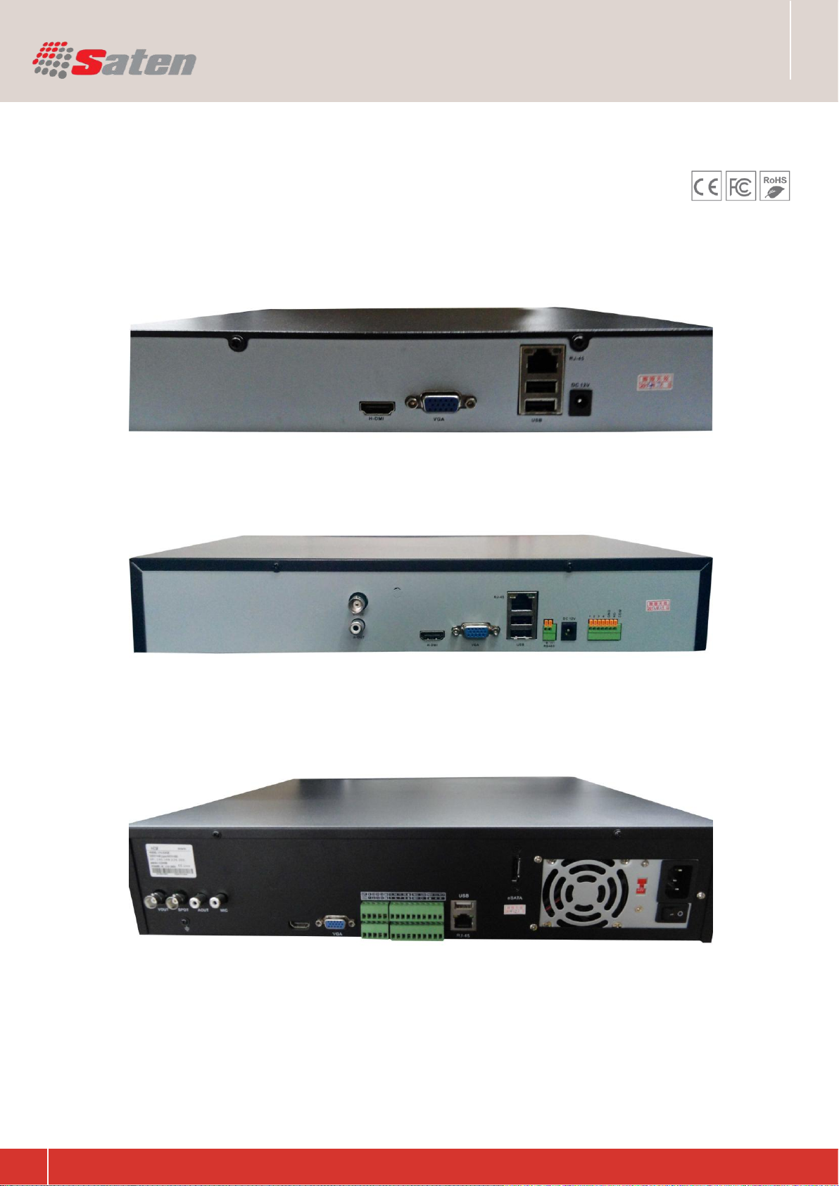
4.5The Rear Panel ...................................................................................................... 8
4.6 The Alarm Cable .................................................................................................. 10
4.7 The Connection of POE....................................................................................... 12
5 Basic Operations Guide.................................................................................................12
5.1 Power On and Off........................................................................................... 12
5.1.1 Power On................................................................................................... 12
5.1.2 Power Off ............................................................................................. 12
5.2 Preview and Login in....................................................................................... 13
5.2.1 Preview...................................................................................................... 13
5.2.2 Login In................................................................................................. 13
5.3 Mode Switching.................................................................................................... 14
5.4 IP Camera....................................................................................................... 14
5.4.1 Add IP Camera..................................................................................... 14
5.4.2 Status Display...................................................................................... 16
5.5 PTZ Control.......................................................................................................... 16
5.5.1 PTZ configuration................................................................................. 17
5.5.2 Quick location....................................................................................... 17
5.6 Search.................................................................................................................. 17
5.7 Record.................................................................................................................. 18
5.8 Alarm............................................................................................................... 18
5.8.1 Alarm Output.............................................................................................. 18
5.8.2 Alarm Configuration ............................................................................. 19
5.8.3 Alarm Status......................................................................................... 20
5.9 Color Setting........................................................................................................ 21
5.10 The Input Method............................................................................................... 21
6 Parameter Settings ........................................................................................................ 22
6.1 Introduction Of Main Menu.................................................................................. 22
6.2 Video Settings...................................................................................................... 22
6.2.1 Basic..................................................................................................... 22
6.2.2 Encoding settings................................................................................. 22
6.2.3 Snapshot.............................................................................................. 23
6.2.4 Net Channel......................................................................................... 23
6.3 Record.................................................................................................................. 24
6.4 Network................................................................................................................ 25
6.5 PTZ Configuration................................................................................................ 27
6.6 Alarm............................................................................................................... 28
6.6.1 Video Detection ......................................................................................... 28
6.6.2 Alarm input........................................................................................... 28
6.6.3 Alarm out.............................................................................................. 29
3

Network Video Recorder
User Manual
Network Video Recorder
6.7 System ............................................................................................................ 29
6.7.1 Base........................................................................................................... 29
6.7.2 Display....................................................................................................... 30
6.7.3 Storage...................................................................................................... 30
6.7.4 Abnormity................................................................................................... 31
6.7.5 Status......................................................................................................... 32
6.7.6 Maintain..................................................................................................... 32
6.7.7 Account...................................................................................................... 32
6.7.8 RS232........................................................................................................ 33
7 Web and Client............................................................................................................... 34
7.1 Web Operation..................................................................................................... 34
7.1.1 Network Connection.................................................................................. 34
7.1.2 The control installation and the user login logout...................................... 34
7.1.3 The Interface of Web Operations.............................................................. 35
7.1.4 The Real-time Monitoring.......................................................................... 35
7.1.5 PTZ Control ............................................................................................... 37
7.1.6 Configuration ............................................................................................. 37
7.1.7 Search Record........................................................................................... 38
7.1.8 Alarm Configuration................................................................................... 39
7.1.9 About.......................................................................................................... 39
7.2 The Client Operations.......................................................................................... 39
8 Appendix A Expansion ................................................................................................... 40
8.1 function............................................................................................................ 40
8.1.1 DDNS Function.......................................................................................... 40
8.1.2 PTZ Control....................................................................................................... 42
8.2 HDD Capacity Calculation .............................................................................. 43
8.2.1 Reference of HDD Capacity Calculation................................................... 43
8.2.2 Hard disk problem ..................................................................................... 44
8.3 Common Faults............................................................................................ 45
9 Appendix B: P2P Web Operation Manual...................................................................... 47
9.1 Device Configuration ...................................................................................... 47
9.1.1 Config P2P Function in device ............................................................... 47
9.2 P2P Web Operation........................................................................................ 49
9.2.1 ActiveX Installation ................................................................................. 49
9.2.2 Login Interface........................................................................................ 53
9.2.3 Device Management............................................................................... 55
9.2.4 Real time Video Monitor ......................................................................... 55
9.2.5 PTZ Control............................................................................................. 57
9.2.6 Log out.................................................................................................... 58
9.3 Device Upgrade.............................................................................................. 58
9.4 Q&A................................................................................................................. 59
4

Network Video Recorder
User Manual
Network Video Recorder
The following content is about use of the product, the prevention of danger as well as preventing property
from the loss. Please be sure to comply.
1. Please placed NVRs within the permissible range of temperature and humidity.
2. Do not install the NVRs in a damp, dust or soot place.
3. Place the product horizontally and pay attention to preventing it from falling.
4. Installed in a well-ventilated place and do not block the vent.
5. Do not place containers filled with on the device.
6. Do not place other equipments above the product.
7. Do not disassemble this product.
8. Please select the hard disk recommended by manufacturers and suitable for the requirements of the
NVR.
1. Precautions
5
Please prevail in kind. The manual is for reference only.
This manual may contain inaccurate data or printing error.
The products described in this manual may be updated at any time.
Screenshots of the manual is not in a machine and only for display.
If in doubt, obtaining a copy of the latest procedure or the additional document, please contact with the com-
pany's after-sales department.
2. Declaration
3.1. Product Overview:
This product is designed specifically for the field of video surveillance and adopts H.264 video compression,
hard disk recording, TCP/IP transmission and a Linux based OS in addition to some of the advanced tech-
nology in the information technology industry. This enables a more stable, reliable and high picture quality.
This product complies with standards of GB 20815-2006《video security surveillance digital video re-
cording》promulgated by the State. At the same time, the product supports the ONVIF protocol (base on
《ONVIF ™ Core Specification》Version 2.2) and is compatible with the network cameras which supports
ONVIF protocol. This product can realize the switching of NVR mode or mixed mode (Mixed mode can both
connect with analog channels and network cameras when the NVR modes only connect with network cam-
eras) ,recording, playback, monitoring, synchronization of audio and video. Besides the products support
advanced control technology and strong network data transmission capacity.
3. Product Introduction

Network Video Recorder
User Manual
Network Video Recorder
3.2. Feature:
Real-time monitoring
Have a composite video signal interface and support TV, VGA or HDMI output simultaneously.
Compression function
Use H.264 video compression standard and G.711 audio compression standard and have high definition,
low code rate of the video coding and the storage.
Recording function
Support timing, linkage alarm, motion detection, SATA hard and local hard disk, NVR data backup and net-
work backup.
Video playback function
Achieve searching videos by a variety of conditions, playback in local and network. Support multiple videos
playback, fast playing, slow playing and frame-by-frame playback. Video playback can display the exact time
of the incident. Provide timeline retrieving page for quick searching.
Camera control and alarm
Be controlled by the remote camera and equip many alarm input interfaces.Be connected to various types of
alarm devices. Dynamic detection, video loss, video block, multiple alarm output and scene lighting control
can be realized.
Communication Interface
Equip USB 2.0 high-speed interface or ESATA interface and allow many backup devices. Equip standard
Ethernet interface. Plug and play in a variety of network conditions,
Network functions
Support TCP / IP, UDP, RTP / RTSP, DHCP, PPPOE, DDNS, NTP etc.Support real-time network monitoring,
video playback, control and management functions; built-in WEB Server, you can directly access through a
browser.
Mode of operation
You can operate by the front panel or the mouse. Equip a simple, intuitive graphical interface.
6

Network Video Recorder
User Manual
Network Video Recorder
4.1. Unpacking Inspection:
When you receive a product, check it according to the packing list inside the box.
4.2. Installation Preparation:
Preparation
Prepare a Cross Screwdriver.
Steps
Remove the metal top cover by removing two screws from the sides of the cover.
Place the hard disks on a flat table and tighten the screws.
Connect the power and the data lines to the HDD.
Reinstall the metal top cover and tighten the screws.
Caution
Only use the HDD specified by the manufacturer.
The HDD will be formatted automatically during booting and it may cause data loss.
The total duration of video data saved is decided by the HDD‟s capability and the NVR‟s parameters
(recording setup, encoding setup). Please refer to 9.3.
4.3. Installation of the burner:
Preparing for Installation
You need a Phillips screwdriver.
The burner installation steps
Unscrew the screw on the side of the chassis and open the case cover.
Use a screwdriver to remove the bracket fixed in middle of the disk.
Open the front panel door and remove the baffle inside.
Connect the burner data cable and the power cord.
Fix the chassis cover.
Precautions
The installation of the built-in burner is only for specific DVR and affects disk space for installation and inter-
faces.
4.4. The Front Panel:
Description: The following figure shows a 16-channel embedded DVR front panel, please prevail in kind.
4. Installation
7

Network Video Recorder
User Manual
Network Video Recorder
2U NVR
8
1U NVR
Index Name Function
1 Power switch Receive remote control signal;
2 USB interface Connect USB devices such as U drive
3 Remote control receiver Receive remote control signals
4 Power/RUN/REC/
NET/ALARM
LED
Light for power on state / the machine to work/video
status/
network connection/alarm trigger
5 DVD burner DVD burning
6 Direction key Cursor keys , select menu option
ENTER confirmation key Menu setup confirmation
7 Channel selection key Achieving channel selection single , picture to enlarge
8
Function key
Menu key ESC return key
FN accessibility key PTZ dome control key
REC video key PLAY playback key
PRE next PAUSE pause key
NEXT preceding STOP stop key
MODE image key MUTE mute key
9 Shuttle key Playback fast forward Rewind control screen switch
4.6. The Rear Panel:

Network Video Recorder
User Manual
Network Video Recorder
2U NVR
9
1U NVR
4U NVR

Network Video Recorder
User Manual
Network Video Recorder
10
Rear Panel:
Index Name Function
1 Video input 16-channel video input (BNC)
2 Audio input 16-channel audio input (RCA)
3 Video output 1 channel video output interface(BNC)
4 Audio output 1-channel audio output interface (RCA)
5 Intercom input 1-channel intercom input
6 Extension interface Loop-out extention interface
7 RS 232 interface 1-channel RS232 communication interface
8 VGA interface 1-channel VGA display interface
9 HDMI interface HDMI HD output interface
10 LAN interface 1-channel network interface (RJ45)
11 USB interface 1-channel USB Interface (available to U disk backup or
12 I/O Alarm, serial interface Alarm input/output interface , PTZ interface
13 Fan outlet interface ATX power supply fan air outlet
14 Power interface AC power connector
4.6. The Alarm Cable:
Examples of alarm input connections
The alarm input is the switch quantity input. If the alarm input signal is not switch quantity signal but voltage
signal.
Examples of alarm output connections
Alarm input and output connections
Alarm input
A. Alarm input is grounding alarm input.
B. Alarm input demand is the grounding voltage signal.
C. When the alarm is connected with two NVRs or connected with NVR and other equipments, it should be
isolated by relay.
Alarm output
Alarm output can not be connected with high-power load (no more than 1A). When forming the output loop it
must prevent the big current from relay damage. Use
the contact isolator when there is a high-power load

Network Video Recorder
User Manual
Network Video Recorder
11
PTZ decoder connections
A. The grounding of the PTZ decoder and NVR must be shared otherwise the common-mode voltage will
lead to the PTZ control failure. The shielded twisted pair
is recommended.
B. Avoid the entrance of high voltage. Make the layout reasonably. Take precaution from the thunder.
C. In the outlying end connect 120Ω resistance paralleled to reduce the inflection and insure the signal qual-
ity.
D. The 485 AB lines of NVR can not connected with other 485 output equipments paralleled.
E. The voltage between the AB lines of the decoder must be less than 5V
Front equipment grounding note
Bad grounding can lead to the burnout of the chip.
Alarm input type unlimited
The NVR alarm output port is constant opening type
4-CH Alarm Terminal
Note: Alarm input, the need to ground phase, (NO) is opening type.
8-CH and 16-CH Alarm Terminal
Note: Alarm input, the need to ground phase, (NO)is opening type, (NC)is closing type ,(NO)is the common

Network Video Recorder
User Manual
Network Video Recorder
12
Alarm input port specification
1 channels alarm input. Alarm input type unlimited.
The grounding and the com port of the alarm sensor are parallel (The alarm sensor is external power sup-
ply).
The grounding of the alarm and the NVR should be shared.
The NC port of the alarm sensor must be connected with the NVR alarm input port.
The grounding of the power supply and the alarm sensor must be shared when used in external power sup-
ply.
Alarm output port specification
1 channels alarm output. There is external power supply when using the external alarm equipment.
Please refer to the relay relevant parameters to avoid the overload that damages main machine.
Alarm output port relay parameters
Speed dome connections
1. Connect the 485 lines of the speed dome with the NVR 485 interface.
2. Connect the video line with the DVR video input.
3. Electrify the speed dome.
4.7. The Connection of POE :
Step 1: Supply the NVR with the 12V DC power.
Step 2: Connect the POE module with 48V directly power.
Note: 48V voltage is not safe, please pay attention to the use of electricity.
Step 3: The side of the network cable is connected to the POE network interface and the other side is con-
nected to the network camera. The distance of POE power i s not more than 100 m theoretically.
5.1. Power On and Off:
5.1.1 Power On
Correctly install and power on the NVR. When the power indicator lit up, the VCR will automatically
start.NVR will automatically detect hardware state of the device during the starting. The booting process will
continue for about 30 seconds. After boot, the equipment sounds and then enters the state of multi-screen
real-time video surveillance.
5.1.2 Power Off
Press the power key for three seconds to achieve shutdown.Enter the NVR‟s [main menu]- shutdown] and
select [shutdown].
5. Basic Operations Guide

Network Video Recorder
User Manual
Network Video Recorder
13
5.2. Preview and Login in:
5.2.1 Preview
After the device is turned on, you will enter the real-time monitoring interface. Right click and the following
interface will pop up.
5.2.2 Login In
Click the image above with [main menu], and then input the user name(default:admin)and the password

Network Video Recorder
User Manual
Network Video Recorder
14
5.3. Mode Switching:
The NVR can work in mixed mode or NVR mode. Mixed-mode can be connected with both analog cameras
and network cameras while NVR mode can only support IP cameras.
Enter [configuration]- [system]-[channel mode] to select the mode. Restart to complete the setting.
5.4. IP Camera:
5.4.1 Add IP Camera

Network Video Recorder
User Manual
Network Video Recorder
15
[Search] Select the appropriate protocol and search. The IPCs and the device should in the same LAN. Dou-
ble click the search results and it will add the IPC automatically and return to the previous page. Fill in the
user name and password to complete.
Network channels are used to display remote IPCs. The addition of IPCs shows as the following interface.
Enter [video]-[net channel].
First open [OPEN].
[Channels] Choose a local channel to display.
[Protocol] It is selected according to the type that the IPC supports.
[IP] Input the IPC‟s IP address.
[Port] Fill in the ONVIF port of the IPC
[Username] Fill in the user name of the IPC.
[Password] Fill in the password of the IPC.
[Remote Detect] After completing the above parameters, click the detect button to return the connection
status.

Network Video Recorder
User Manual
Network Video Recorder
16
5.5. PTZ Control:
When connect with a network ball, right click the corresponding network channel and select [PTZ] to enter
into the PTZ interface. If access to a simulated ball machine, enter [Main Menu] - [PTZ] to modify the PTZ
protocol, the baud rate and address bits. Then right click in the corresponding channel and select [PTZ]. The
PTZ control interface is shown as the following interface.
5.4.2 Status Display
Right click in the real-time monitoring screen and select [net channel] to view the status of the network chan-
nels.
Click to enter the PTZ configuration page.

Network Video Recorder
User Manual
Network Video Recorder
17
Refer to 8.2 about more details.
5.5.1 PTZ configuration
The direction of PTZ, steps, zoom, focusing, iris, preset points, cruising between points, patrols, sweeping
the boundary, calling an auxiliary switch, light switch, horizontal rotation are controlled with the usage of the
arrow keys.
The [Step] is mainly used to control directions. The figure can be set from 1 to 8.
Directly click or to adjust zooming, sharpness and brightness adjustment.
PTZ supports eight directions.
5.5.2 Quick location
Quick location: <SIT> is in the middle of the direction arrows. Make sure that the protocol supports this func-
tion. PTZ will turn to the clicked point and move it to the centre of screen. It also supports zooming. Drag the
mouse in the quick location page. The dragged box supports 4 to 16 times zooming. Hold the mouse and
drag it up to complete zoom of the box. Drag it down to narrow the box.
Refer to 7.1.5 about more details
5.6. Search:
In real-time monitoring screen, right click and select (search) to enter the searching interface.

Network Video Recorder
User Manual
Network Video Recorder
18
5.7. Record:
In real-time monitoring screen, right click and select (record) to enter the interface
(Manual) It has the highest priority and corresponding channels will record for whole days after chosen.
(Schedule) Record according to recoding configuration.
(Stop) Stop recording.
5.8. Alarm:
5.8.1 Alarm Output
This menu manages alarm output parameters and displays the current state of alarm
Index Type Description
1 Calendar Date and time
2 Choose the time Input the date and time of records searched.
3 Playback control It can achieve a full screen, circle playback, stopping /
playing, pausing, fast playing, slow playing and the
previous/next frame on a suspended state .
4 Recoding mode There are alarm recording and regular recording for
selecting.
5 Select channels to
query Choose the channels for querying.
6 Playback controls It can achieve a full screen and circle playback.
7 Search Click the button to search.
8 Backup Choose files and click “ ”to backup. Then select a
storage device and recording files.
9 The list of records 128 video records are shown in the list.
Type: R—normal record, A—alarm record, M—motion
detection record.
10 The channel for
playback Choose a channel in which the record plays back.

Network Video Recorder
User Manual
Network Video Recorder
19
Notice: Some models don‟t have the local alarm, please refer to the products descriptions.
5.8.2 Alarm Configuration
Detect
Enter [main menu]-[detect].
[Process] Click the button to set the alarming time, linkage and the handling method
(Channels) The number of channels that are in alarm
status.
(Schedule) Alarm output is in control of alarm configuration.
(Manual) Alarm output is on and the status is active.
(Stop) Alarm output is off and the status is inactive.
(Status) The current status of alarm output.
[Channel] Select the channel.
[Alarm type] Dynamic monitoring, video loss and video
blind can be selected.
:Open the enable switch.
[Sensitivity] Set sensitivity of the network channels.
[Set area] It should be set in the IPC.
[Linkage Set] When produce an alarm, you can activate the linkage of records, PTZ, touring and capturing

Network Video Recorder
User Manual
Network Video Recorder
20
Alarm Input
Enter [main menu]-[alarm]-[alarm input].
5.8.3 Alarm Status
If you select [Show Message] in linkage settings, the following message will pop up when the alarm occurs.
[Alarm input channel no.] Select a channel.
[Enable] Select the enable switch.
[Type] It can be normal open or close.
[Process] and [Linkage] Refer to [Detect].
This manual suits for next models
2
Table of contents