SATO KEIRYOKI Sigma-II NS II-Q User manual

1. Carrying handle
2. Pen arm for temperature
3. Cartridge pen
4. Recording cylinder
5. Pen lifting bar
6. Pen lifting lever
7. Acrylic Cover
8. Bracket
9. Fine adjustment screw for
temperature
10. Pen arm for humidity
11. Fine adjustment screw for
humidity
12. Temperature sensor
(Bimetal strip)
13. Venthole
●COMPONENTS
②
③
④
⑤
⑥
①⑦
⑧
⑨
⑪
⑫
⑬
⑩
Thermohygrograph
Model NSⅡ
-Q
NSⅡ
-S
3-4,Kanda-kajicho,Chiyoda-ku,Tokyo101-0045Japan
URL:http://www.sksato.co.jp/english/ V.02.18

−
1
−
For battery-operated type
(No. 7210-00/7211-00)
For spring-wound type
(No. 7215-00)
< Procedure for use >
Thank you for purchasing the Sigma II Thermohygrograph.
・This instrument is designed to measureand record the indoor temperature and humidity. Donot use it for other purposes.
・ Read this manual thoroughly before use and keep it in a safe place for future references.
This product is strictly inspected and securely packed at shipment, however the indicated value may shift due to excessive shock or vibration during
transportation. After unpacking, place the unit in a stable atmosphere for two hours or more before use and confirm that the indicated value is within
the specified accuracy by comparison with the reliable thermohygrometer such as Assmann psychrometer. If the indicated value is out of accuracy
specified, adjust the value referring to the “Indication adjustment.”
If there are anything unclear, contact us or the dealer from which you purchased the instrument.
Turn carrying handle to
left until it stops.
1. Lift the cover and remove
it.
2. Remove packing material.
3. Open the lid pulling the knob
outside. After insert the
batteries, close the lid while
pulling the knob outside.
4-A Fully wind spring at the top of
cylinder with the thumbscrew.
4-B
Pull the pen lifting lever
fully toward you.
5. Remove the cylinder
holding nut.
6. Remove chart holder.
7. Wind chart.
NB : The chart is not attached on cylinder at shipment
8. Attach the chart holder.
9.

−
2
−
Mount recording cylinder
to the main shaft.
Attach cylinder holding
nut.
Supplementary explanation of usage
10. 11. Cut tape that secures
upper pen arm.
12. Remove the holding clip
that secures lower pen arm
by sliding itupward.
13. Remove cap for cartridge
pen by turning it counter-
clockwise.
14.
Push pen lifting lever away
from you until it stops. Set time.
15. 16. Put acrylic cover on.
17. 18. Turn the carrying handle
clockwise until it stops.to
secure the cover.
19.
1. Remove the acrylic cover and the packing materials that hold the mechanical
parts during transportation. (Photos No. 1 to 3)
2. ・ Quartz type: Insert batteries. (Photo No. 4-A)
・ Spring-wound type
: Raise up the thumbscrew at the top of the cylinder and turn it counter-
clockwise to wind spring. Be careful of winding too much. (Photo No. 4-B)
3. Attach chart (Photo No. 6 to 11)
・ Wind the chart onto the cylinder so that the end of the chart for start is put
under the other end.
・ Be sure to align both ends of the paper at the position of chart holder.
・ Ensure that the lower edge of the chart align with the cylinder bottom collar.
4. Remove the cap of cartridge pen. (Photo No. 14)
5. Set the time (Photo No. 16)
・ Turn the cylinder clockwise first and stop it at the position on 1 or 2 hours forwarder
than the present time. Set it to the present time turning the cylinder counter-
clockwise. This will enable you to set time correctly avoiding play in drum gear
mechanism.
NB : Time may be incorrect if procedure is done in wrong order.
6. Install the acrylic cover. (photo No. 17 to 19)
Make the carrying handle
vertical and install the acrylic
cover so that the plate “SK
SATO” comes to the front.

−
3
−
● Precautions
1. Handling batteries (for battery-operated model (quartz type) only)
・ At loading batteries, use two C size batteries and confirm that the polarities
(+/−) are correct.
・ Replace the batteries to new ones every year. Be sure to replace all two
batteries with new ones of the same type.
・ Do not get the batteries charged.
・ Do not dispose of used batteries in a fire.
・ For environmental protection, dispose of used batteries in compliance with local
rules and regulations.
NB : When the liquid leaks, immediately wipe or wash out the liguid.
2. Replacement of cartridge pen
・ Pull pen lifting lever toward you until it stops.
・ To remove the cartridge pen, pull toward the direction of the arrow.
・ To attach the pen, slide it onto the pen arm until it stops.
・ Don’t touch pen tip. If the finger grease adhere, ink
will not flow smoothly.
・ Cartridge pen will last about six months (in use of 7
day chart), but life may be shortened by the
conditions of use.
NB : Be sure to use our dedicated cartridge pens.
3. Attaching chart
Make sure the markings on the chart are aligned where the overlap occurs, and
the lower edge of the chart is against the bottom lip of the cylinder.
NB : Be sure to use our dedicated charts.
4. Carrying instrument
Before lifting the instrument with the handle, make sure that it is locked.
● Installation place
Do not use in the followings. Use in such environments may causes of error in
indication and record.
・ In a place with vibration, shock or inclination.
・ Outdoor use (exception in a instrument screen)
・ At exhaust port of airconditioner or at a place subject to direct sunlight.
・ In dusty of sooty environments.
・ Use of blocking the ventholes of the acrylic cover.
・ Near splashing water.
・ In corrosive gases.
● Other precautions
・ Use the instrument within the measuring range.
・ Be sure to remove the packing materials that hold the mechanical parts
attached at shipment.
・ Do not cover the instrument with a vinyl or like for waterproof purpose or etc. If
so, correct value will not be obtained.
・ Don’t disassemble the instrument. Doing so may result in failure.
・ Remove the batteries during transportation.
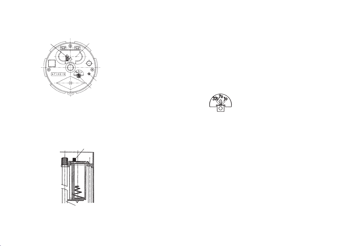
● Indication adjustment
Fine adjustment is available, however please avoid using except when necessary
as the instrument is calibrated at our factory. If some adjustment is required,
follow these procedures:
To increase indicated readings, turn the fine adjustment screw counterclockwise.
To lower the indicated readings, turn the fine adjustment screw clockwise. (Figs A-
1 and A-2) Fine adjustable range (Temperature: ±3℃. Humidity: ±5%)
It is desirable to calibrate the instrument periodically once a year.
Fine adjustment-temperature Fine adjustment-humidity
A-1 A-2
−
4
−
For battery-operated model (Quartz type)
●Recording cylinder
● Loading batteries
・
To open the lid of the battery compartment, pull the knob outside.
・
Insert two C size batteries into the battery compartment with the correct
polarities (+/−).
・
Close the lid while pulling the knob outside.
●Verifying operation
Cylinder starts rotating soon after the batteries are installed. Confirm that LED
(green) is blinking.
Knob
●Checking battery condition with LED
LED (green) goes out when the voltage of the battery becomes 2.2VDC ±10% or
less under normal ambient. At this time, replace the batteries to the new ones
immediately.
NB : Recording cylinder stops operation in approx. one month after the LED
goes out under normal ambient.
●Changing cylinder speed
The cylinder speed switch is set for 7-day
operation at factory shipment.
Set the switch at the top of cylinder to 1D or
32D for 1-day or 32-day operation. (Fig. 2)
NB: Be sure to replace the chart according
to its recording period.
Fig. 1
Battery
compartment
Knob
LED (Green)
Cylinder speed switch
Fig. 2 Cylinder speed switch

−
5
−
2. Install 1-day chart for 1-day operation
1-day chart (400 sheets/box) may be purchased separately.
3. Install the recording cylinder
Confirm that the pinion is engaged properly with the gear as shown in
Fig. E.
●Optional charts and cartridge pens
For No. 7210-00 and 7215-00 (range: −15 to 40℃, 0 to 100%rh)
No. 7210-60 1-day chart (400 sheets/box)
No. 7210-62 7-day chart (55 sheets/box)
(One box is a standard accessory)
No. 7210-64 32-day chart (55 sheets/box)
(Applicable for No. 7210-00 only)
For No. 7211-00 (range: −10 to 50℃, 0 to 100%rh)
No. 7211-60 1-day chart (400 sheets/box)
No. 7211-62 7-day chart (55 sheets/box)
(One box is a standard accessory)
No. 7211-64 32-day chart (55 sheets/box)
No. 7210-90 Cartridge pen (violet)
No. 7210-92 Cartridge pen (red)
For spring-wound model
●Change cylinder speed pinion
Fig. E Side view of cylinder
Z: indicates number of pinion teeth
22 teeth (φ10.7mm) ..................................1-day operation
18 teeth (φ9.0mm) ....................................7-day operation
Fig. A Bottom of cylinder Fig. B
1. Exchange 7-day pinion to 1-day pinion
・
Remove the 7-day pinion referring to Figs A and B
・
Remove the 1-day pinion from the holder on the base and store the 7-day
pinion on it. (Fig. C)
・
Install the 1-day pinion shaft marked ‘Z=24H’. Push the pinion straight onto the
shaft with thumb pressure until it stops. (Fig. D).
(Bottom view of cylinder that was removed
from the main shaft)
Cylinder holding nut
Main shaft
Pinion Gear
Botton
for
7-day
operation
168H
Z=18 Chart holder
retaining hole
Lift on both sides
of pinion with tips
of screwdrivers
Pinion
Screw-
driver
Bottom of
cylinder
for
1-day
operation
Z=22
24H
Fig. C Fig. D
gear for 1-day
operation
pinion
stops when a meets b.
a
b
pinion shaft

−
6
−
SPECIFICATIONS
*Specifications subject to change for improvement with or without notice.
7210-00 / 7211-00 7215-00Cat No.
Model
Drum
rotation
Sensors
Measuring
range
Accuracy
Minimum
graduation
Cylinder
rotation
accuracy
Battery life
Storage
ambient
Dimensions
Weight
Accessories
approx. 3.6 Kg approx. 3.3 Kg
One box (55 sheets) of 7-day chart for 1 year use
A chart holder (except 7211-00), Test result
Two “C” size batteries (applicable for quartz type only)
±5 min. per day
±35 min. per 7 days
±160 min. per 32 days (for quartz type only)
Temperature : Bimetal strip
Humidity : Human hair bundle
Temperature : ±1℃ (at +10 to 30℃)
±2℃ (other than above)
Humidity : ±3%RH (at +15 to 25℃, 20 to 95%)
: ±5%RH (other than above)
Temperature : 1℃
Humidity : 1%
Temperature: -15 to 40℃ (for No. 7210-00 and No. 7215-00)
-10 to 50℃ (for No. 7211-00)
Humidity : 0 to 100% RH
●External fan (option)
The external fan (option) can be attached to the
acrylic cover. The fan improves response by
directly pulling surrounding air into the instrument.
●Warranty
Our products are warranted to be free from defects in materials and workmanship
for a period of one year from date of shipment. If repair or adjustment is
necessary and has not been the result of abuse or misuse within the one-year-
period, please return the units on - Freight Prepaid - basis and correction of the
defect will be made without charges. We alone will determine if the product
problem is due to deviations or customer misuse.
Out-of-warranty products will be repaired on charge basis.
Return of items
Authorization must be obtained from us before returning items for any reason.
When applying for authorization, please include data regarding the reasons the
items are to be returned.
about 1 year at use of 7 day rotation -----
0 to 40℃, 20 to 80%RH(no condensing)
336 (W) × 148 (D) × 295 (H) mm
NS Ⅱ-Q (Quartz type) NS Ⅱ-S (Spring-wound type)
1 day, 7 day and 32 day changed
by cylinder speed switch
1 day and 7 day changed
by gear

1. Carrying handle
2. Pen arm for temperature
3. Cartridge pen
4. Recording cylinder
5. Pen lifting bar
6. Pen lifting lever
7. Acrylic Cover
8. Bracket
9. Fine adjustment screw for
temperature
10. Pen arm for humidity
11. Fine adjustment screw for
humidity
12. Temperature sensor
(Bimetal strip)
13. Venthole
●COMPONENTS
②
③
④
⑤
⑥
①⑦
⑧
⑨
⑪
⑫
⑬
⑩
Thermohygrograph
Model NSⅡ
-Q
NSⅡ
-S
3-4,Kanda-kajicho,Chiyoda-ku,Tokyo101-0045Japan
URL:http://www.sksato.co.jp/english/ V.02.18
This manual suits for next models
4
Table of contents
Other SATO KEIRYOKI Thermographic Camera manuals