sauermann AMI 310 User manual

USER MANUAL
AMI 310
MULTIFUNCTION INSTRUMENT


Table of contents
1 PRESENTATION............................................................................................................................................................ 5
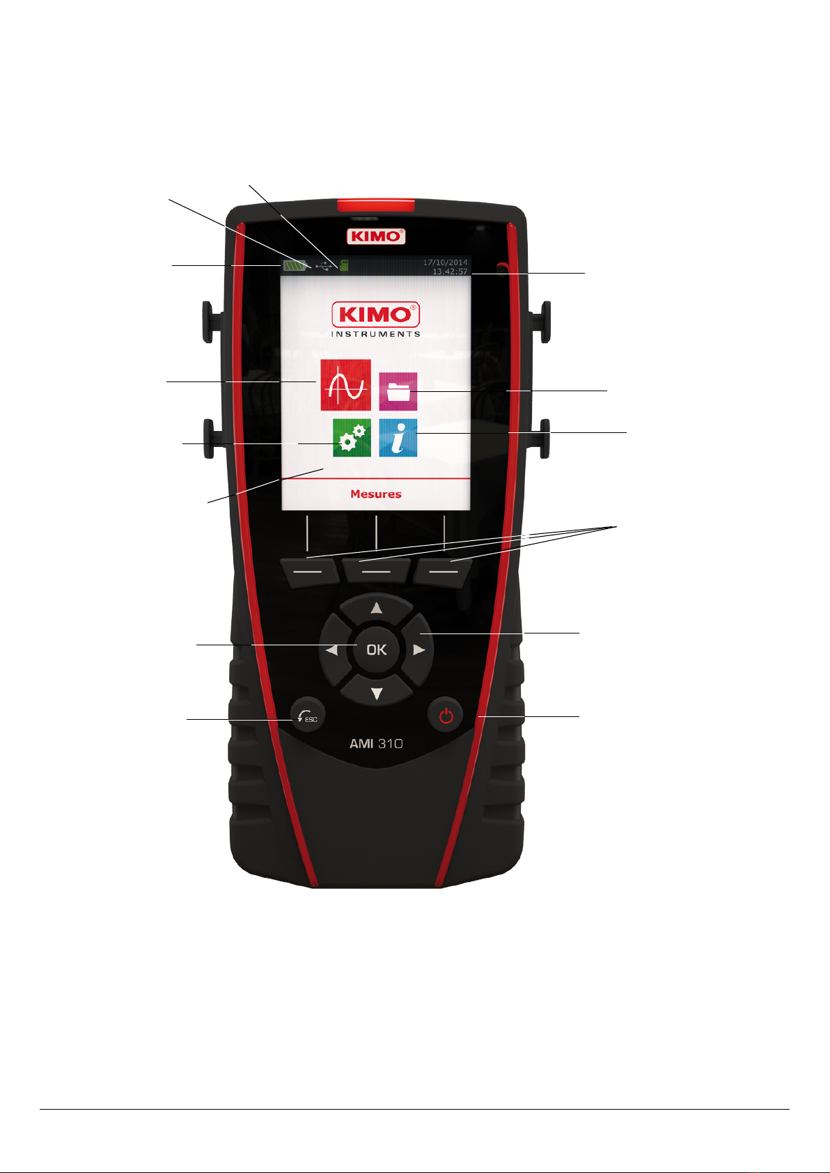
1.1 Instrument description..........................................................................................................................................5
1.2 Remove battery....................................................................................................................................................5
1.3 Insert S card.......................................................................................................................................................6
1.4 irective 2014/53/EU...........................................................................................................................................6
2 CONNECTIONS OF THE AMI 310..................................................................................................................................7
2.1 Main features.......................................................................................................................................................7
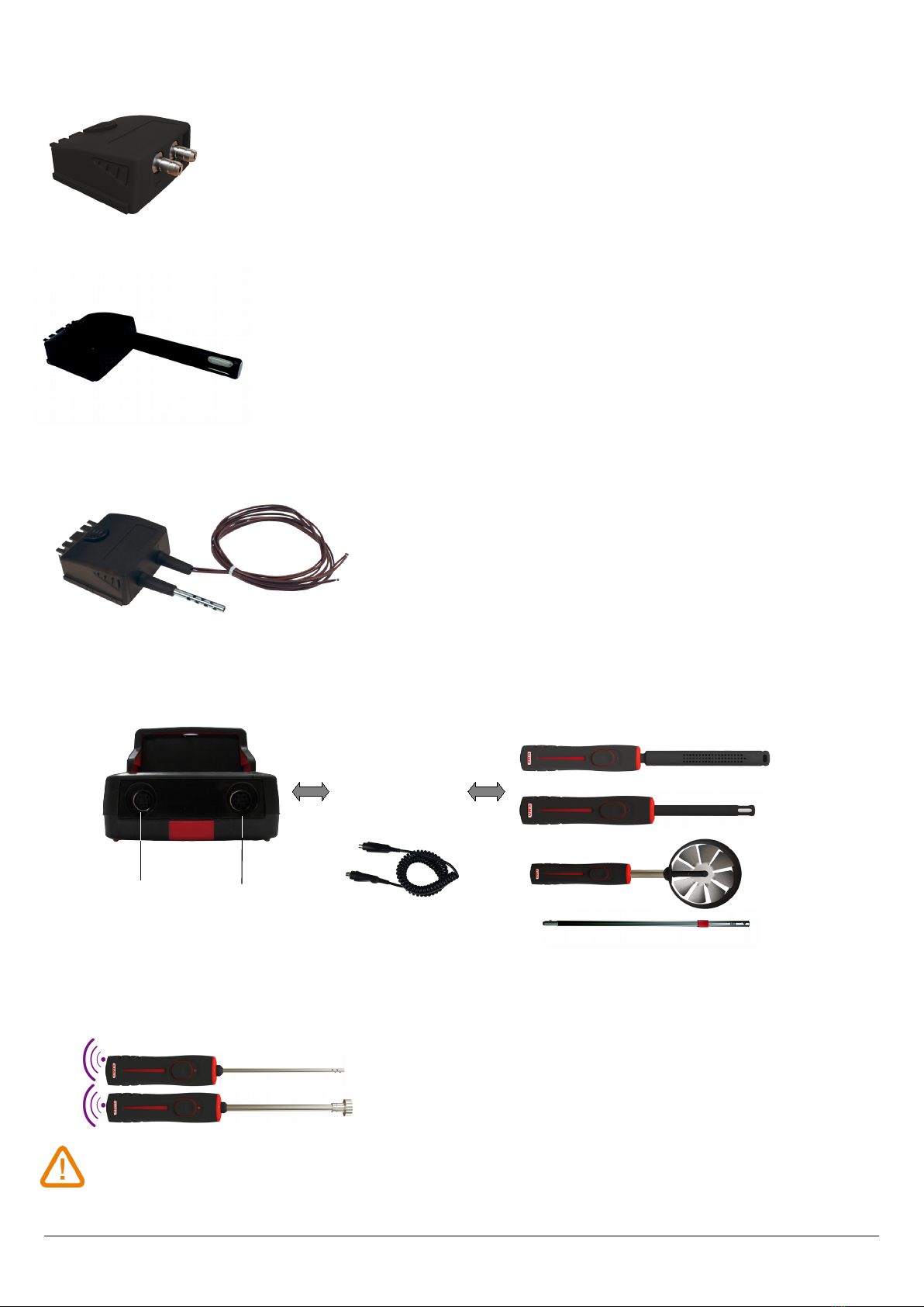
2.2 Connections.........................................................................................................................................................7
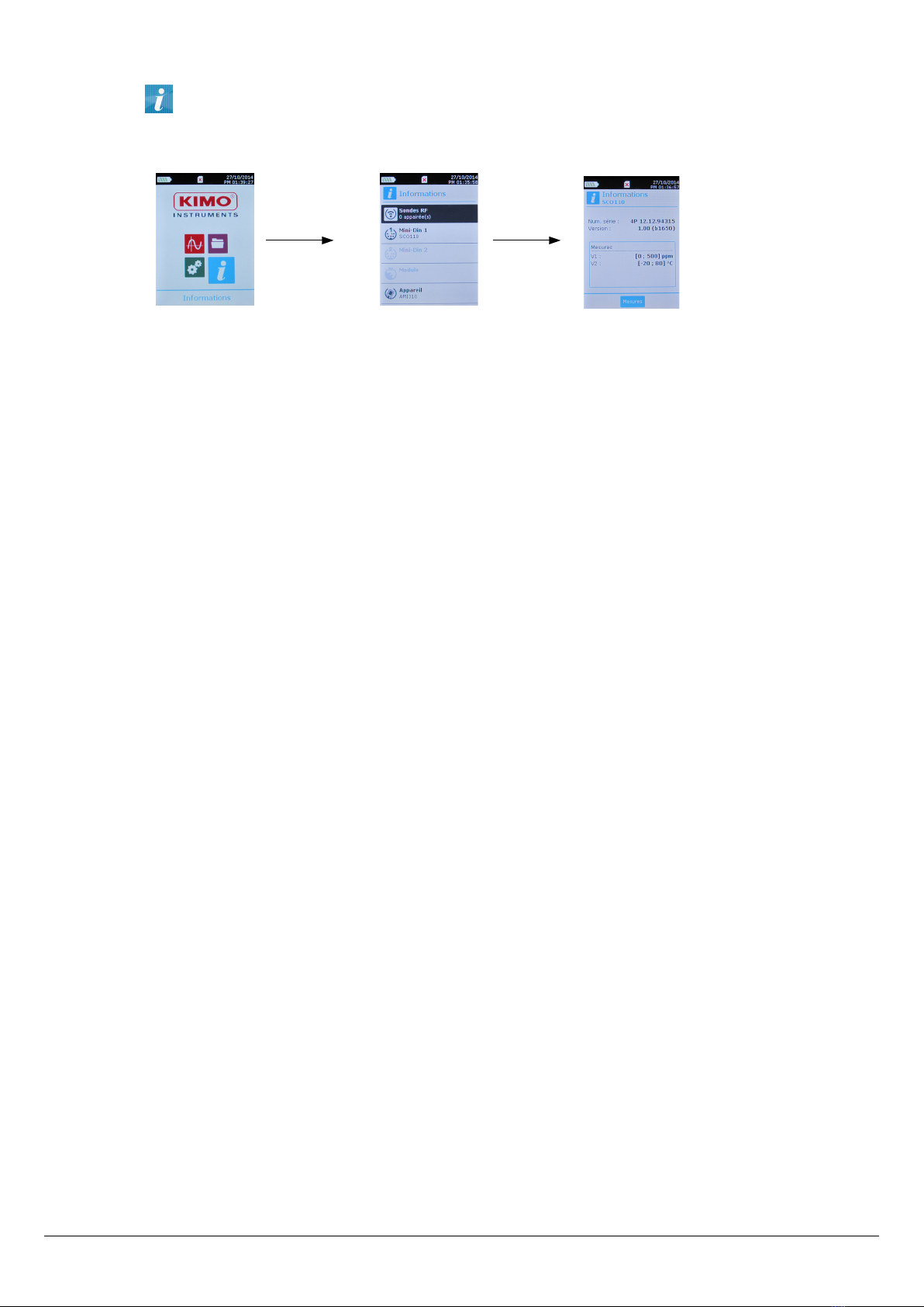
3 INFORMATION............................................................................................................................................................. 9
4 SET THE INSTRUMENT................................................................................................................................................10
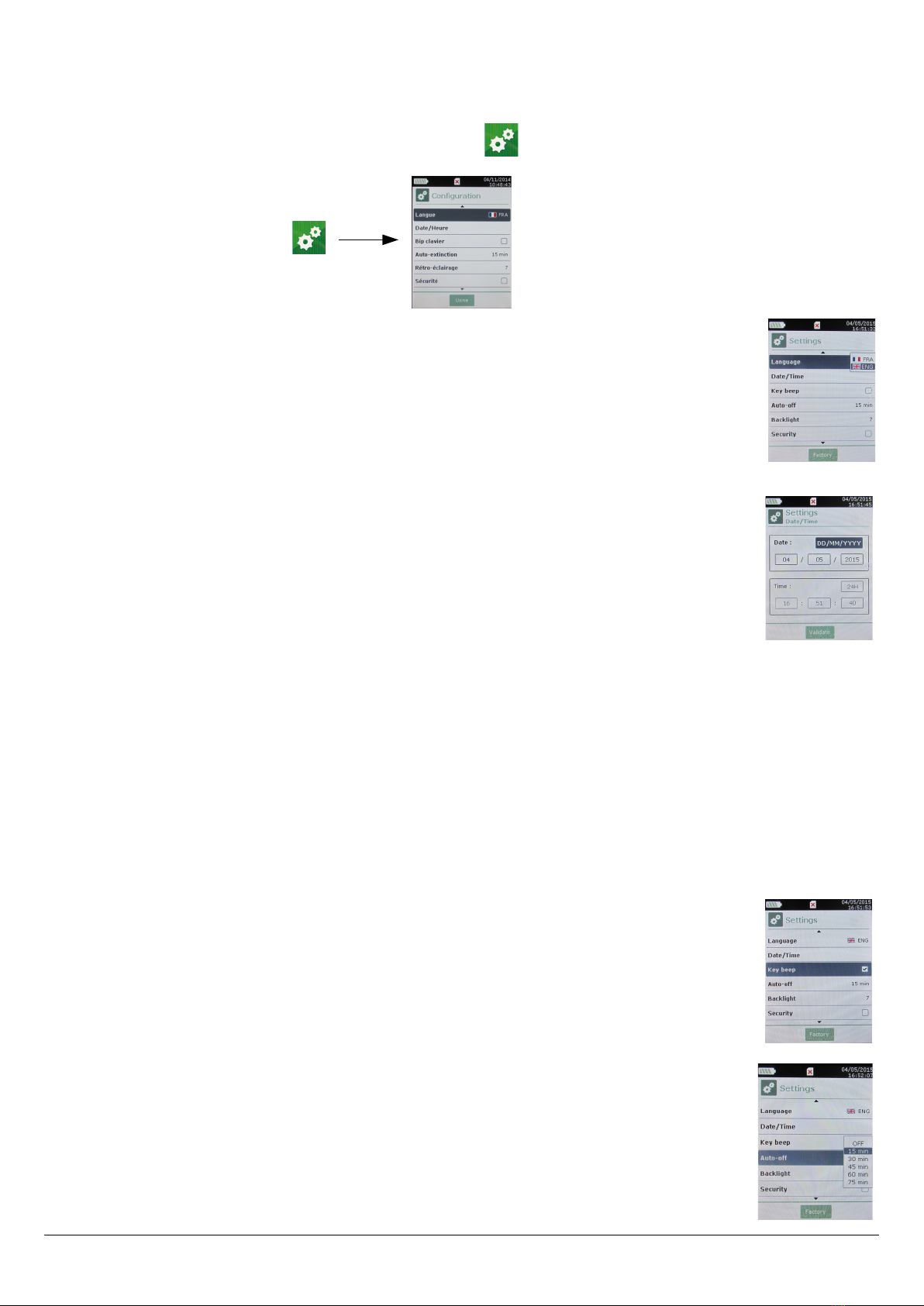
4.1 Set language...................................................................................................................................................... 10
4.2 Set date and time...............................................................................................................................................10
4.3 Activate or deactivate the beep key.....................................................................................................................10
4.4 Set auto-off........................................................................................................................................................10
4.5 Set backlight......................................................................................................................................................11
4.6 Set security........................................................................................................................................................ 11
4.7 Set code............................................................................................................................................................. 11
4.8 Set printing........................................................................................................................................................11
5 SET THE PROBES........................................................................................................................................................ 12
5.1 Use of the wire probes and modules...................................................................................................................12
5.2 Special precautions for air velocity probes...........................................................................................................12
5.3 Use of wireless probes.......................................................................................................................................13
6 CHANNEL CONFIGURATION.......................................................................................................................................14
6.1 In airow mode.................................................................................................................................................. 14
6.2 elta T............................................................................................................................................................... 15
7 START AN RECOR ATASETS..................................................................................................................................16
7.1 Start and record datasets....................................................................................................................................16
7.1.1 Manual dataset..........................................................................................................................................16
7.1.2 Automatic dataset......................................................................................................................................16
7.1.3 View the recorded datasets.........................................................................................................................17
7.2 Launch and save averages..................................................................................................................................17
7.2.1 Point/Point average.....................................................................................................................................17
7.2.2 Automatic average......................................................................................................................................18
7.2.3 Automatic Point/Point average....................................................................................................................18
7.3 COmax.............................................................................................................................................................. 19
7.4 Autozero............................................................................................................................................................ 19
7.4.1 Perform an autozero...................................................................................................................................19
7.4.2 Set an interval between 2 autozeros............................................................................................................20
7.5 Gas leak............................................................................................................................................................ 20
7.6 U coefcient.......................................................................................................................................................20
7.7 Hold-Min./Max...................................................................................................................................................21
7.8 Turbulence index................................................................................................................................................21
8 SETTING OF MEASUREMENT PARAMETERS................................................................................................................22
8.1 Pressure module.................................................................................................................................................22
8.1.1 Unit...........................................................................................................................................................22
8.1.2 Integration................................................................................................................................................. 22
8.1.3 Atmospheric pressure.................................................................................................................................23
8.2 Thermocouple module........................................................................................................................................23
8.2.1 Unit...........................................................................................................................................................23
8.2.2 Type...........................................................................................................................................................23
8.2.3 Alarm......................................................................................................................................................... 23
8.3 Climatic conditions module.................................................................................................................................23

8.3.1 Unit...........................................................................................................................................................23
8.3.2 Alarm......................................................................................................................................................... 23
8.4 U coefcient module..........................................................................................................................................24
8.4.1 Unit...........................................................................................................................................................24
8.4.2 Alarm......................................................................................................................................................... 24
8.5 Vane probe and hotwire probe............................................................................................................................24
8.5.1 Unit...........................................................................................................................................................24
8.5.2 Integration................................................................................................................................................. 24
8.5.3 Alarm......................................................................................................................................................... 24
8.5.4 Normative value.........................................................................................................................................25
8.5.5 Atmospheric pressure.................................................................................................................................25
8.6 Gas leak............................................................................................................................................................ 25
8.6.1 Unit...........................................................................................................................................................25
8.7 CO-CO2/temperature/hygrometry probes.............................................................................................................25
8.7.1 Unit...........................................................................................................................................................25
8.7.2 Alarm......................................................................................................................................................... 25
8.7.3 Atmospheric pressure.................................................................................................................................26
8.8 Tachometry.........................................................................................................................................................26
8.8.1 Unit...........................................................................................................................................................26
8.8.2 Type...........................................................................................................................................................26
8.9 Multifunction and omnidirectional probes...........................................................................................................26
8.9.1 Unit...........................................................................................................................................................26
8.9.2 Alarm......................................................................................................................................................... 26
8.9.3 Integration................................................................................................................................................. 27
8.9.4 Normative values........................................................................................................................................27
8.9.5 Atmospheric pressure.................................................................................................................................27
8.10 Hygrometry probe.............................................................................................................................................27
8.10.1 Atmospheric pressure...............................................................................................................................27
8.10.2 Unit.........................................................................................................................................................27
8.11 Light probe...................................................................................................................................................... 27
8.11.1 Unit.........................................................................................................................................................27
8.11.2 Information on light probe........................................................................................................................27

1 PRESENTATION
1.1 Instrument description
1.2 Remove battery
➢Turn off the instrument.
➢Turn it over.
➢Press the red button while sliding down the battery.
PRESENTATION
5
Function keys
On/Off button
ESC button
Congur tion
menu
Me surement
menu D t set menu
Inform tion menu
Home screen
N vig tion rrows
OK button
B ttery level D te nd time
SD c rd
USB connection
indic tor

1.3 Insert SD card
It is possible to insert a S card in the AMI310 in order to increase its memory.
➢Turn off the instrument.
➢Remove the battery.
➢Insert the S card in its location.
➢Put the battery.
1.4 Directive 2014/53/EU
Hereby, Sauermann Industrie SAS declares that the radio equipment type AMI 310 is in compliance with irective
2014/53/EU. The full text of the EU declaration of conformity is available at the following internet address:
www.sauermanngroup.com
6
PRESENTATION
S card properly
inserted

2 CONNECTIONS OF THE AMI 310
2.1 ain features
•Screen
320 x 240 pixels graphic display, colour screen and backlight. isplay of 6 measurements, 4 simultaneously.
Size: 71 x 53 mm.
•Printer (available as option)
The paper of the instrument is a thermal paper with a 10-year guarantee. It has an easy replacement system of the paper
(Easyload). In addition, printing is fast.
•Battery
Rechargeable Li-ion battery inside the instrument, 16 h battery-life with a pressure module or 14 h a hotwire probe. The
instrument is supplied with a 5 V, 1 A power adapter to load the internal battery. The current loading is indicated by a
battery symbol on the top left of the screen. The orange led on the bottom of the instrument is also on until the full loading
of the battery (the led turns green).
2.2 Connections
•Interchangeable modules
The interchangeable modules have the SMART-2014 system and are automatically recognized once the connection is made
on the instrument.
Thermocouplemodule:
CONNECTIONS OF THE AMI 310
7
Light indicator for
battery charging
USB connection
+ power supply
Mini- IN C2
connection
Battery
Module Location to remove the
module
Probe handle
Mini- IN C1
connection
Allows to measure temperature on Tc1, Tc2, Tc3 and Tc4 channels with wired thermocouples K, J, T
or S probes ended with a male miniature connector
Thermocouple
inputs

Pressure module:
Clim tic conditions module:
U coefcient module:
Allows to calculate the U coefcient thanks to the average of 3 contact
temperature probes, the T thermocouple ambient temperature and the
measurement of external temperature (manually entered or measured by a
wireless temperature probe)
•Wire probes with SMART-2014 system
Wire probes with SMART 2014 system are automatically recognized when connected to the instrument.
•Wireless probe / instrument communication
Wireless communication between probe and instrument with automatic recognition after power-up.
Wireless probes sh ll be loc ted ne r the instrument for initi l recognition. Connection between
AMI 310 nd wireless probes must be est blished.
8
CONNECTIONS OF THE AMI 310
C2 mini- IN
connection
C1 mini- IN
connection
Probes are connected on
min- IN connectors C1 and
/ or C2 (excepted
thermocouple probes)
Overmolded mini- IN
connector with foolproong
system. Cable length 450 mm,
extension 2.4 m.
Allows to measure the differential pressure PΔ and to calculate air velocity and airow with a
Pitot tube or Debimo bl des. It also measures the thermocouple temperature with a wired
thermocouple probe ended with a male miniature connector.
Non-exhaustive list of probes
Allows to measure hygrometry, ambient temperature and atmospheric pressure.

3 INFORMATION
“Information” menu allows to view information about the instrument, probes and module connected to the
“Wireless probe”, “Mini-DIN 1”, “Mini-DIN 2” or “Module” connections. To enter in this menu from home screen,
select the “Inform tion” menu with the arrow keys then press OK.
Av il ble inform tion for probes nd module is:
•Type of probes and module
•ate of the last calibration or adjustment
•Serial number
•Firmware version
•Measuring range
Av il ble inform tion for the instrument is:
•Type of instrument
•ate of the last calibration or adjustment
•Serial number
•Firmware version
•Measuring range
➢The function key “Me surement” allows to access directly to the “Me surement” menu.
INFORMATION
9

4 SET THE INSTRUMENT
The instrument is on.
➢With the arrow keys, go to “Congur tion” menu.
➢Press OK.
4.1 Set language
“Congur tion” screen is displayed.
➢Select “L ngu ge” with the arrow keys then press OK.
Available languages are displayed.
➢Press Up and own arrows to select the required language : FRA, ENG...
➢Press OK.
4.2 Set date and time
“Congur tion” screen is displayed.
➢Select “D te/time” with the arrow keys then press OK.
The screen of conguration for date and time is displayed.
➢Go to the “D te” format with arrow keys then press OK.
➢Select: /MM/YYYY, MM/ /YYYY or YYYY/MM/ then press OK.
➢Go to the day then press OK.
➢With Up and own keys, set the rst digit of the day then go to the following one with right arrow.
➢Press OK to validate.
Perform the same procedure to set the month and year.
➢Go the “Time” format with arrow keys then press OK.
➢Select the time format : “12H” or “4H” then press OK.
If “12H” is selected, it is possible to choose between “AM” for ante meridiem or “PM” for post meridiem.
➢Press OK, select “AM” or “PM” then press OK to validate.
➢Go the time then press OK.
➢With Up and own keys set the rst digit of the day then go to the following one with right arrow.
➢Press OK to validate.
Perform the same procedure to set minutes and seconds.
➢Press function key “V lid te” to leave the screen and to save modications or press Esc to
cancel.
4.3 Activate or deactivate the beep key
“Congur tion” screen is displayed.
➢Select “Key beep” with arrow keys.
➢Press OK to activate or deactivate the beep key.
The box is ticked if the beep is activated and unticked when the beep is deactivated.
4.4 Set auto-off
The auto-off function turns off the instrument after a moment of unused.
It is possible to set the auto-off of the instrument at 15 / 30 / 45 / 60 / 75 / 90 / 105 or 120 minutes or
to deactivate it.
10
SET THE INSTRUMENT

“Congur tion” screen is displayed.
➢Select “Auto-off” with arrow keys then press OK.
➢Select the required duration or OFF to deactivate it with Up and own keys.
➢Press OK to validate.
4.5 Set backlight
“Congur tion” screen is displayed.
➢Select “Backlight” with arrow keys then press OK.
➢Select the backlight level between 1 nd 9 or “Auto” with Up and own keys.
➢Press OK to validate.
4.6 Set security
This part allows to activate or deactivate a security code. This code will be asked when starting the
instrument.
“Congur tion” screen is displayed.
➢Select “Security” with arrow keys.
➢Press OK to activate or deactivated the security.
If the security is activated, please create a security code.
4.7 Set code
If the security is activated, the selected code will be asked when starting the instrument.
“Congur tion” screen is displayed and the security is activated.
➢Go to “Code” then press OK.
➢With arrow keys, set each digit then press OK when the last digit is set.
Modications are validated, the instrument backs to “Congur tion” screen.
4.8 Set printing
“Congur tion” screen is displayed.
➢Select “Printing” with arrow keys then press OK.
➢Go to “Form t” then press OK.
➢Select the ticket format : long or short then press OK.
Long ticket form t: prints the measurement results + header (operator name, date and
time of the intervention, type of instrument and its serial number)
Short ticket form t: prints only the measurement results and the serial number of the
instrument
➢Go to “Logo” then press OK to activate or deactivate it.
The box is ticked when the logo is activated and unticked when the logo is deactivated.
➢Go to “Oper tor” to enter an operator name then press OK.
Keypad is displayed on the bottom of the screen.
➢Select the letters with arrow keys then press OK.
To go from the lower case keypad to the upper case keypad then to the numeric keypad : press the function key:
To delete a letter press the function key “Delete”.
➢Press the function key “Validate” to validate the name.
➢Go to “He der 1” to enter the header name then press OK.
Keypad is displayed on the bottom of the screen.
➢Select the letters with arrow keys then press OK.
➢Press the function key “V lid te” to validate the header 1.
➢Perform the same procedure to enter a name for the “He der 2”, “He der 3” and “He der 4”.
➢Press ESC to back to the “Congur tion” screen and to validate the modications.
SET THE INSTRUMENT
11

5 SET THE PROBES
5.1 Use of the wire probes and modules
•Connect probe
➢Connect the mini- IN cable on the mini- IN connection of the probe.
➢Connect the mini- IN cable with the probe on the instrument.
A beep indicates that the operation has been correctly performed.
➢Go to “Me surement” menu from the home screen.
➢Press OK
Measurement are displayed.
5.2 Special precautions for air velocity probes
12
SET THE PROBES
Probe connection Instrument connection
Arrow in front of
the user
Arrow in front of the user
Bottom of the standard probe
Airflow direction
landmark
Protective tube of the
sensitive element (1)
Sensitive element (velocity)
Sensitive element
(temperature)
Bottom of the telescopic probe
Before ny use of the device with n ir velocity probe, ple se lower the protective tube (1) of
the sensitive element (except v ne probe).
Alw ys use the st nd rd ir velocity probe with the red point in front of the ow.
Alw ys use the telescopic probe with the white point in front of the ow.

5.3
Use of wireless probes
•Add wireless probe
OR
SET THE PROBES
13
With arrow keys, go to
“Inform tion” menu
then press OK.
In “Inform tion” menu go to
“Wireless probe” then press
OK.
On the bottom of the
screen press the
function key “Cre te”.
Turn on the wireless probe and keep it
press until the light blinks
Pairing is in progress
The probe information is displayed With the function
key “Me s.” It is possible to back to the
measurement screen. It is also possible to delete the
wireless probe pressing the function key “Delete”.
With arrow keys, go to
“Me surements”
menu then press OK.
In “Me surement” menu,
press the function key
“Ch nnels”.
Press the function key
“Probes”.
With the arrow keys, select “Add wireless
probe...” then press OK.
On the bottom of the screen press
the function key “Cre te”.
Turn on the wireless probe and
keep it press until the light
blinks
Pairing is in progress
The probe information is displayed
With the function key “Me s.” It
is possible to back to the
measurement screen. It is also
possible to delete the wireless
probe pressing the function key
“Delete”.

6 CHANNEL CONFIGURATION
The channel conguration allows to modify the displaying of the measured parameters.
The instrument is on.
➢With the arrow keys, go to “Me surement”.
➢Press OK.
➢Press the function key “Ch nnels”.
The different functions of the probe are displayed.
It is possible from the “Ch nnels” menu to add or delete some measurements.
➢Press the function key “Delete” in order to delete the selected measurement.
➢Press the function key “Add” to display the selected measurement.
➢Press “Add” to add a measurement on the screen (the default measurement displayed on the screen are the
primary measurements).
It is possible from the “Ch nnels” menu to choose the displaying order of the measurement on the screen.
➢With arrow keys, select the measurement to modify and press OK.
➢Go to the line “Ch nnel num.” then press OK.
➢Select the channel number and press OK.
6.1 In airow mode
Airow:
In the “ch nnels” menu:
➢Select with arrow key the sub-menu “Airow” then press OK.
➢Select “Ch nnel num.” and press OK.
➢Select a channel number and press OK.
➢Go to the line “Type” then press OK.
➢Select the required type : “Rect”, “Circ” or “K f ctor” and press OK*.
K f ctor: The air ow in a ventilation opening, Qv (m³/h), can be evaluated from a differential pressure
measurement on this ventilation opening, ΔP (Pa). The K factor is a coefcient used to measure the
volumetric ow rate on an air vent. This coefcient is given in the technical features of the air vent.
If the coefcient is not specied in the air vent technical document or directly on the air vent, please request
the manufacturer to know this coefcient.
From the air vent coefcient, named K, it is possible to calculate the volumetric ow rate:
Qv
=
K
×
√
ΔP
*For a hotwire probe, K factor is not available. It is possible to select “Cone” in addition to “Rect” and “Circ”:
➢To select “Cone”, go to the line “Cone” then press OK.
•Select the type of cone: K35, K75, K120 or K150 and press OK.
•Press “Me sures” to display the measurements.
*For a Ø100 mm vane probe, K factor is not available. It is possible to select “Cone” in addition to “Rect” and “Circ”:
➢To select “Cone”, go to the line “Cone” then press OK.
•Select the type of cone: K25 or K85 and press OK.
•Press “Me sures” to display the measurements.
If the type is Rect or Circ:
➢Go to “Rect” or “Circ”, press OK, select its size then press OK to validate.
14
CHANNEL CONFIGURATION

➢Go to the line “Are s” then press OK.
It is possible to change units and size.
➢Select “Unit” with the arrow keys then press OK. Select mm or in and press OK.
➢To modify areas, select with arrow keys “Rect.” or “Circ.” and press OK.
➢Select the size to modify in the list and press OK.
➢Set the size with arrow keys between 1 nd 2500 mm then press OK.
➢For a K f ctor*: go to “K f ctor”, press OK, select the K factor then press OK to validate.
➢If the airow is calculated with a pressure module, then go to “d/p elem.” to select the differential pressure
element. Press OK then select the element between “Pitot L” (coefcient: 1.0015), “Pitot S” (coefcient: 0.84),
“Débimo” (coefcient: 0.8165) and “Other”. If “Other” is selected, then enter its differential pressure
coefcient between 0 and 9.9999.
➢Go to the line “K2 f ct.” and press OK to select or unselect the K2 factor.
K2 factor is a coefcient which is applied to correct the ow rate only for the rectangular or circular surfaces.
6.2 Delta T
elta T is a function which allows to dene a temperature difference calculated between two temperature channels of the
same type.
➢Connect the thermocouple module then the probes.
In the “Ch nnels” menu:
➢Select with arrow keys the sub-menu “Delt T” then press OK.
➢Select “Ch nnel number” and press OK.
➢Select a channel number and press OK.
➢Select the channels in which elta T will be calculated.
➢Go to “Ch nnel A” with arrow keys and press OK.
➢Select the channel T1, T2, T3 or T4 and press OK.
➢Go to “Ch nnel B” with arrow keys and press OK.
➢Select the channel T1, T2, T3 or T4 and press OK.
➢Press the key “Me surement”.
The instrument displays the measurements.
CHANNEL CONFIGURATION
15
* For more details about the K factor, please see page 14.

7 START AND RECORD DATASETS
The instrument in on.
➢Select with arrows keys “Me surement” menu.
➢Press OK.
➢Select with arrows keys the measurement in which the dataset will be performed.
➢Press “Functions” key then select “D t set” with arrow keys and press OK.
ataset menu is displayed.
➢Go to line “N me” with arrow keys and press OK.
A keypad is displayed on the bottom of the screen.
➢Select the letters with arrow keys then press OK.
To go from the lower case keypad to the upper case keypad then to the numeric keypad:
press the function key:
To delete a letter press the function key “Delete”.
➢Press the function “Validate” to validate the name of the dataset.
A dataset is composed of several dated measuring points. You can choose between an automatic
dataset or a manual dataset.
➢Go to “Type” with arrow keys then press OK.
➢Select “M nu.” for manual or “Auto.” for automatic.
➢Go to “St rt” then press OK.
7.1 Start and record datasets
7.1.1 Manual dataset
A m nu l d t set is composed of measuring points selected by the operator.
Manual mode is selected, measurements are displayed.
➢Press OK to validate a measuring point.
➢Press OK as many time as the required number of points.
➢Press the function key “S ve”.
The instrument displays the measuring dataset : type of dataset, number of points, date, minimum, maximum,
average and standard deviation.
The dataset is automatically recorded.
➢Press OK to display the graph of the results.
➢Press the function key “Zoom+” to display the detail of the calculated points.
➢Press Esc key to back to the dataset screen.
➢Press the function key “Print” to print the dataset.
Printing mode is displayed.
➢Go to the line “Ch nnels info” and press OK to print the channels on the printing ticket.
➢Go to the line “Det ils” and press OK to print details of the dataset on the printing ticket.
➢Press the function key “V lid te” to print.
The instrument backs to the dataset display.
➢Press Esc to back to “me surement” menu.
7.1.2 Automatic dataset
An utom tic d t set is composed of measuring points with interval of time.
Automatic mode is selected, measurements are displayed.
➢Press the function key “Dur tion” to set the dataset duration.
➢Press OK on the line “Dur tion”.
➢Go to “Hour” with the arrow keys then press OK, set the duration with arrow keys then press OK.
16
START AND RECORD DATASETS

➢Perform the same procedure for the minutes and seconds.
➢Press the function key “V lid te” when the duration is set.
➢Press OK on the line “Interv l”.
➢Go to “min” with the arrow keys then press OK, set the duration with arrow keys then press OK.
➢Perform the same procedure for the seconds.
➢Press the function key “V lid te” when the interval is set.
➢Press Esc to back to measuring dataset.
➢Press the function key “St rt” to launch the measuring dataset.
The countdown starts.
•It is possible to stop the measuring dataset by pressing the function key “Stop”.
•Press “St rt” to restart the dataset.
•Press “Dur tion” to modify the duration.
•Press “S ve” to save the dataset.
The instrument displays the measuring dataset : type of dataset, number of points, date, minimum, maximum,
average and standard deviation.
The dataset is automatically recorded.
➢Press OK to display the graph of the results.
➢Press the function key “Zoom+” to display the detail of the calculated points.
➢Press Esc key to back to the dataset screen.
➢Press the function key “Print” to print the dataset.
Printing mode is displayed.
➢Go to the line “Ch nnels info” and press OK to print the channels on the printing ticket.
➢Go to the line “Det ils” and press OK to print details of the dataset on the printing ticket.
➢Press the function key “V lid te” to print.
The instrument backs to the dataset display.
➢Press Esc to back to “Me surement” menu.
7.1.3 View the recorded datasets
➢Go to the “D t set” menu with the arrow keys from the home screen.
The different measuring datasets are displayed. They are listed by date.
➢To delete all the datasets : press the function key “Del ll”.
➢To delete just one dataset : go to the dataset to delete with the arrow keys and press the function key “Delete”.
➢A conrmation window opens : select YES to conrm the deletion or NO to cancel.
7.2 Launch and save averages
The instrument is on.
➢Go to “Me surement” with the arrow keys.
➢Press OK.
➢Press the function key “Functions” then select “Aver ges” then press OK.
“Aver ge” menu is displayed.
7.2.1 Point/Point average
This function allows to calculate the average value of various points that you can select.
➢Go to “Point/Point” line in the “Aver ges” menu and press OK.
➢Press OK to add measuring points.
The instrument displays the type of dataset, number of points, date, minimum, maximum, average and standard
deviation.
➢Press the function key “Det ils” to get details for each point.
➢Press the function key “S ve” to save the Point/Point average.
START AND RECORD DATASETS
17

A keypad is displayed on the bottom of the screen.
➢Select the letters with arrow keys then press OK.
To go from the lower case keypad to the upper case keypad then to the numeric keypad : press the function key:
To delete a letter press the function key “Delete”.
➢Press the function key “V lid te” to validate the name.
The recap of the Point/Point average is displayed.
➢Press OK to display the graph.
➢Press the function key “Zoom+” to display the detail of the calculated points.
➢Press Esc key to back to the dataset screen.
➢Press the function key “Print” to print the dataset.
Printing mode is displayed.
➢Go to the line “Ch nnels info” and press OK to print the channels on the printing ticket.
➢Go to the line “Det ils” and press OK to print details of the dataset on the printing ticket.
➢Press the function key “V lid te” to print.
The instrument backs to the Point/point average display.
➢Press Esc to back to “Me surement” menu.
7.2.2 Automatic average
This function allows to calculate an average value that the device measured in an interval chosen time.
➢Go to “Autom tic” line in the “Aver ges” menu and press OK.
➢Press the function key “St rt” to start the measurement.
uration is displayed.
➢Press the function key “Stop” to stop the measurements.
Measurements, average, minimum and maximum values, standard deviation and duration are displayed.
➢Press the function key “St rt” to launch a new automatic average.
➢Press the function key “S ve” to save the results.
A keypad is displayed on the bottom of the screen.
➢Select the letters with arrow keys then press OK.
To go from the lower case keypad to the upper case keypad then to the numeric keypad : press the function key:
To delete a letter press the function key “Delete”.
➢Press the function key “V lid te” to validate the name.
The recap of the automatic average is displayed..
➢Press OK to display the graph.
➢Press the function key “Zoom+” to display the detail of the calculated points.
➢Press Esc key to back to the dataset screen.
➢Press the function key “Print” to print the dataset.
Printing mode is displayed.
➢Go to the line “Ch nnels info” and press OK to print the channels on the printing ticket.
➢Go to the line “Det ils” and press OK to print details of the dataset on the printing ticket.
➢Press the function key “V lid te” to print.
The instrument backs to the automatic average display.
➢Press Esc to back to “Me surement” menu.
7.2.3 Automatic Point/Point average
This function allows to calculate the average value of various points, calculated themselves on a duration beforehand
dened.
➢Go to “Auto Pt/Pt” line in the “Aver ges” menu and press OK.
A duration is displayed on the bottom right of the screen.
➢Press the function key “Dur tion” to modify the duration if necessary.
➢Go to “min” with the arrow keys then press OK, set the duration with arrow keys then press OK.
➢Perform the same procedure for the seconds.
18
START AND RECORD DATASETS

➢Press the function key “V lid te” when the interval is set.
➢Press OK to start the measurement.
A the end of the measuring dataset, measurements, average, minimum and maximum values, standard deviation
and duration are displayed.
➢Press OK to add a new measuring point to the calculation.
The countdown starts.
➢Press the function key “Det ils” to get details of the results.
➢Press the function key “S ve” to save the results of the automatic average.
A keypad is displayed on the bottom of the screen.
➢Select the letters with arrow keys then press OK.
To go from the lower case keypad to the upper case keypad then to the numeric keypad : press the function key:
To delete a letter press the function key “Delete”.
➢Press the function key “V lid te” to validate the name.
The recap of the dataset is displayed.
➢Press OK to display the graph.
➢Press the function key “Zoom+” to display the detail of the calculated points.
➢Press Esc key to back to the dataset screen.
➢Press the function key “Print” to print the dataset.
Printing mode is displayed.
➢Go to the line “Ch nnels info” and press OK to print the channels on the printing ticket.
➢Go to the line “Det ils” and press OK to print details of the dataset on the printing ticket.
➢Press the function key “V lid te” to print.
The instrument backs to the automatic point/point average display.
➢Press Esc to back to “Me surement” menu.
7.3 COmax
For a CO/temperature probe, it is possible to calculate a COmax. This function allows to measure on an adjustable duration
the maximum value of CO reached during this time interval..
➢In the “Functions” menu, select with arrow keys “COm x” then press OK.
Measurements and a 30 s duration are displayed.
➢Press the function key “Dur tion” to modify the countdown.
➢Go to “min” with the arrow keys then press OK, set the duration with arrow keys then press OK.
➢Perform the same procedure for the seconds.
➢Press the function key “V lid te” when the duration is set.
➢Press the function key “Start” to launch the measurement dataset of COmax.
•It is possible to stop the measuring dataset by pressing the function key “Stop”.
•Press “St rt” to restart the dataset.
•Press “Dur tion” to modify the countdown.
At the end of the duration, the instrument displays the results of COmax.
➢Press Esc to back to “Me surement” menu.
7.4 Autozero
It is possible to perform an autozero with a pressure module.
This sub-function allows to manually compensate the potential deviations of the sensitive element over time through a
manual adjustment of the zero.
7.4.1 Perform an autozero
For the 500 Pa pressure module with solenoid v lve:
➢In the menu “Functions”, go to “Autozero” then press OK.
START AND RECORD DATASETS
19

For 2500 Pa, 10000 Pa, 500 mbar and 2000 mbar pressure modules without solenoid v lve:
➢Unplug the 2 pressure connections tubes from the pressure module.
➢In the menu “Functions”, go to “Autozero” then press OK.
7.4.2 et an interval between 2 autozeros
This function is only v il ble for 500 P pressure modules.
➢Press the function key “P r ms” then press OK.
➢Go to “Interv l AutoZ” then press OK.
➢Set the interval between 0 and 6 minutes.
➢Press Esc to back to measuring screen.
7.5 Gas leak
➢Connect the gas leak probe on the AMI310 then turn it on.
If the probe is connected for more than 1 minute, the measuring screen displays and shows the gas concentration.
If the probe is connected for less then 1 minute, the screen shows the remaining time of pre-heating then measurements
are displayed.
➢In the “Functions” menu, select with arrow keys “G s le k” then press OK.
➢Press “Threshold” to modify the alarm threshold. Use arrow keys to modify the threshold value then press OK to
validate the threshold and back to measuring screen.
The alarm threshold corresponds to the value on the right of the bargraph.
When this threshold is exceeded, the instrument produces a continuous beep.
7.6 U coefcient
U coefcient module allows to calculate the thermal transmittance coefcient of a wall (U coefcient). U characterises
the quantity of heat that goes through a wall in continuous operation. It is a key point to determine thermal leak.So it
allows to estimate the insulation of a wall: the lower the value, the more insulated the wall.
For building renovations, this coefcient is one of the most important values to estimate the their loss and their energy use.
To use the U coefcient function, a U coefcient module must be connected and active.
➢Go to “Me surement” menu then press OK.
➢Press the function key “Functions” then go to “U coeff.” with the arrow keys then press
OK.
➢Press the function keys “P r ms”, set the outdoor temperature with the arrow keys then
press OK.
The instrument makes the calculation of the U coefcient.
➢Press “S ve” to save the dataset.
A window appears.
➢Select “N me” then press OK to modify the name of the dataset.
A keypad appears on the bottom of the screen.
➢Select the letters with the arrow keys then press OK.
➢Select “Type” then press OK to select the type of the dataset.
➢Select “M nu” whith the arrow keys then press OK.
➢Select “L unch” then press OK.
➢To save a measuring point, press OK.
➢Press OK as many time as the required number of points.
➢Press “S ve” to save the dataset.
The recap of the dataset is displayed.
➢Press OK to display the graph.
20
START AND RECORD DATASETS
Table of contents