SAWAFUJI ELECTRIC ENGEL MT35F-G4-P User manual

MODEL (Digital display type) :
MT35F-G4-P 0642 032 0T60
MT35F-U1D-P 0642 032 0310
MT45F-G4-G 0642 042 0T52
MT45F-G4-P 0642 042 0T60
MT45F-U1D-P 0642 042 0R40
MT45F-G4-L 0642 042 0T70
2020.02
#1
SERVICE MANUAL

●FOR REFRIGERATOR USERS
・Failing to service properly may result in poor reliability of the refrigerator.
・Read this booklet carefully and perform servicing with great care.
・
●FOR SAFETY OF YOURSELF
・
●SAFETY SYMBOLS
・The following warning labels in this booklet indicate precautions for service work.
Comply with what each symbol indicates whenever it appears.
●REFRIGERATOR CODE NUMBERS
・This manual is compatible with described model in below.
Please check refrigerator model name and number in lable .
(Lable place as picture)
NUMBER MODEL NAME
0642 032 0T60 MT35F-G4-P
0642 032 0310 MT35F-U1D-P
0642 042 0T52 MT45F-G4-G
0642 042 0T60 MT45F-G4-P
0642 042 0R40 MT45F-U1D-P
0642 042 0T70 MT45F-G4-L
This service manual describes maintenance procedures for ENGEL refrigerator.
This manual is intended for repair engineers who are familiar with basics service skills and
knowledge for ENGEL refrigerator.
This manual does not guarantee correct maintenance when service is done by a non-skilled
worker without technical knowledge.
Note that the content of this booklet including product specifications is subject to change for
improvement without notice.
Always comply with the procedures, directions, and work tips in this booklet when
servicing the refrigerator.
To secure safe and correct servicing, read this manual thoroughly in advance and check
if there are protective equipment and appropriate tools and service parts ready as well
as technical skills necessary to perform servicing.
May lead to death or serious injury if failed to comply with this
precaution
May lead to injury if failed to comply with this precaution
Lead to failure of the refrigerator set or its components if failed
to comply with this precaution
WORK TIPS

1.
SPECIFICATIONS ・・・・・・・・・・・・・・・・・・・・・・・・・・・・・・・・・・・・・・・・・・・・・・・・・・・・・・・・・・・・・・・・・・・・・・
1
■ Specifications Table ・・・・・・・・・・・・・・・・・・・・・・・・・・・・・・・・・・・・・・・・・・・・・・・・・・・・・・・・・・・・・・・・・・・・・・
1
■ Exterior / Interior Dimensions ・・・・・・・・・・・・・・・・・・・・・・・・・・・・・・・・・・・・・・・・・・・・・・・・・・・・・・・・・・・・・・・・・・・・・・
3
2.
INSTALLATION A REFRIGERATOR ・・・・・・・・・・・・・・・・・・・・・・・・・・・・・・・・・・・・・・・・・・・・・・・・・・・・・・・・・・・・・・・・・・・・・・
4
■ How to Install the Refrigerator ・・・・・・・・・・・・・・・・・・・・・・・・・・・・・・・・・・・・・・・・・・・・・・・・・・・・・・・・・・・・・・・・・・・・・・
4
■ Temperature Setting ・・・・・・・・・・・・・・・・・・・・・・・・・・・・・・・・・・・・・・・・・・・・・・・・・・・・・・・・・・・・・・・・・・・・・・
4
■ Electric Power Sources ・・・・・・・・・・・・・・・・・・・・・・・・・・・・・・・・・・・・・・・・・・・・・・・・・・・・・・・・・・・・・・・・・・・・・・
5
■ Onboard Direct Wiring with Optional Kit ・・・・・・・・・・・・・・・・・・・・・・・・・・・・・・・・・・・・・・・・・・・・・・・・・・・・・・・・・・・・・・・・・・・・・・
6
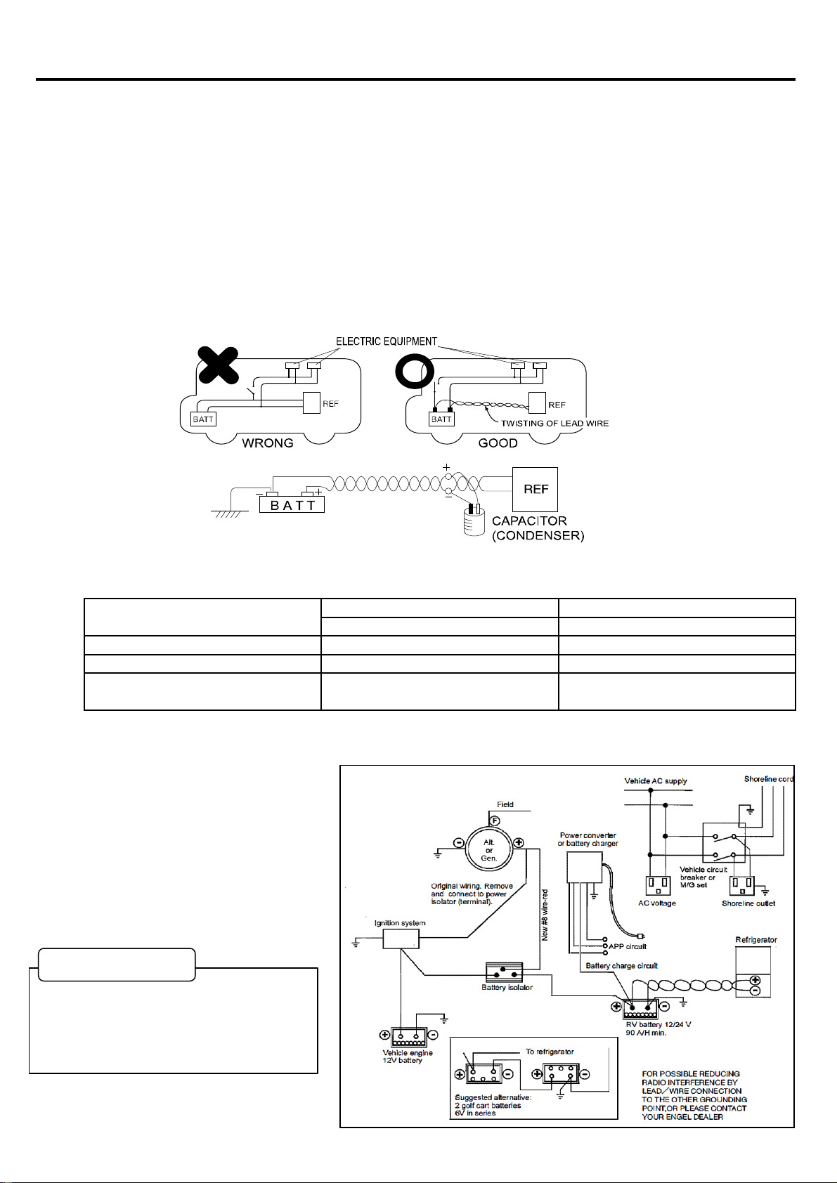
■ Wiring Diagram of Dual Battery Hookup ・・・・・・・・・・・・・・・・・・・・・・・・・・・・・・・・・・・・・・・・・・・・・・・・・・・・・・・・・・・・・・・・・・・・・・
6
3.
PART NAME ・・・・・・・・・・・・・・・・・・・・・・・・・・・・・・・・・・・・・・・・・・・・・・・・・・・・・・・・・・・・・・・・・・・・・・
7
■ MT35F / MT45F ・・・・・・・・・・・・・・・・・・・・・・・・・・・・・・・・・・・・・・・・・・・・・・・・・・・・・・・・・・・・・・・・・・・・・・
7
4.
CONNECTING DIAGRAM ・・・・・・・・・・・・・・・・・・・・・・・・・・・・・・・・・・・・・・・・・・・・・・・・・・・・・・・・・・・・・・・・・・・・・・
8
■ Block Diagrams & Wiring Diagrams ・・・・・・・・・・・・・・・・・・・・・・・・・・・・・・・・・・・・・・・・・・・・・・・・・・・・・・・・・・・・・・・・・・・・・・
8
5.
TROUBLE SHOOTING ・・・・・・・・・・・・・・・・・・・・・・・・・・・・・・・・・・・・・・・・・・・・・・・・・・・・・・・・・・・・・・・・・・・・・・
9
■ Error Message (Digital display of temperature controller)・・・・・・・・・・・・・・・・・・・・・・・・・・・・・・・・・・・・・・・・・・・・・・・・・・・・・・・・・・・・・・・・・・・・・・
9
■ Trouble flowchart ・・・・・・・・・・・・・・・・・・・・・・・・・・・・・・・・・・・・・・・・・・・・・・・・・・・・・・・・・・・・・・・・・・・・・・
9
・Refrigerator is too Cold ・・・・・・・・・・・・・・・・・・・・・・・・・・・・・・・・・・・・・・・・・・・・・・・・・・・・・・・・・・・・・・・・・・・・・・
9
・Does not get Cold ・・・・・・・・・・・・・・・・・・・・・・・・・・・・・・・・・・・・・・・・・・・・・・・・・・・・・・・・・・・・・・・・・・・・・・
10
・Cooling is Weak ・・・・・・・・・・・・・・・・・・・・・・・・・・・・・・・・・・・・・・・・・・・・・・・・・・・・・・・・・・・・・・・・・・・・・・
11
・Typical Problem ・・・・・・・・・・・・・・・・・・・・・・・・・・・・・・・・・・・・・・・・・・・・・・・・・・・・・・・・・・・・・・・・・・・・・・
12
・Technical Data ・・・・・・・・・・・・・・・・・・・・・・・・・・・・・・・・・・・・・・・・・・・・・・・・・・・・・・・・・・・・・・・・・・・・・・
12
6.
CHECK POINT & CHECK METHOD ・・・・・・・・・・・・・・・・・・・・・・・・・・・・・・・・・・・・・・・・・・・・・・・・・・・・・・・・・・・・・・・・・・・・・・
13
【Check 1】 Special Fuse & Blade Fuse ・・・・・・・・・・・・・・・・・・・・・・・・・・・・・・・・・・・・・・・・・・・・・・・・・・・・・・・・・・・・・・・・・・・・・・
13
【Check 2】 Output Voltage of the Compressor ・・・・・・・・・・・・・・・・・・・・・・・・・・・・・・・・・・・・・・・・・・・・・・・・・・・・・・・・・・・・・・・・・・・・・・
13
【Check 3】 Check the Resistance at the Coil if Compressor. ・・・・・・・・・・・・・・・・・・・・・・・・・・・・・・・・・・・・・・・・・・・・・・・・・・・・・・・・・・・・・・・・・・・・・・
13
【Check 4】 Resistance of Thermistor ・・・・・・・・・・・・・・・・・・・・・・・・・・・・・・・・・・・・・・・・・・・・・・・・・・・・・・・・・・・・・・・・・・・・・・ .
14
【Check 5】 Resistance of Control Assy ・・・・・・・・・・・・・・・・・・・・・・・・・・・・・・・・・・・・・・・・・・・・・・・・・・・・・・・・・・・・・・・・・・・・・・
14
【Check 6】 Compressor Rated Current ・・・・・・・・・・・・・・・・・・・・・・・・・・・・・・・・・・・・・・・・・・・・・・・・・・・・・・・・・・・・・・・・・・・・・・
15
【Check 7】 Resistance of Thermistor ・・・・・・・・・・・・・・・・・・・・・・・・・・・・・・・・・・・・・・・・・・・・・・・・・・・・・・・・・・・・・・・・・・・・・・
15
7.
REPLACING PARTS ・・・・・・・・・・・・・・・・・・・・・・・・・・・・・・・・・・・・・・・・・・・・・・・・・・・・・・・・・・・・・・・・・・・・・
16
【How to Replace Cooling Unit 】 ・・・・・・・・・・・・・・・・・・・・・・・・・・・・・・・・・・・・・・・・・・・・・・・・・・・・・・・・・・・・・・・・・・・・・・
16
【How to Replace Power Supply】 ・・・・・・・・・・・・・・・・・・・・・・・・・・・・・・・・・・・・・・・・・・・・・・・・・・・・・・・・・・・・・・・・・・・・・・
18
【Change Battery for Thermometer】・・・・・・・・・・・・・・・・・・・・・・・・・・・・・・・・・・・・・・・・・・・・・・・・・・・・・・・・・・・・・・・・・・・・・・
19
【How to Replace Fan Motor】 ・・・・・・・・・・・・・・・・・・・・・・・・・・・・・・・・・・・・・・・・・・・・・・・・・・・・・・・・・・・・・・・・・・・・・・
19
CONTENTS

■ Specifications Table
MT35F-G4-P MT45F-G4-G MT45F-G4-P MT45F-G4-L
0642 032 0T60 0642 042 0T52 0642 042 0T60 0642 042 0T70
STORAGE VOLUME ℓ (liter) 32
in 14.3×16.1×25.5
mm 364×408×648
in 10.6×10.6×15
mm 270×270×380
CABINET
DOOR
CABINET
DOOR
DOOR
CABINET
AC
DC
DC12V
DC24V
AC
LBS. 46.3
Kg 21
※1 We took the largest mesurement ( including latch and handles)
※2 At an ambient temperature of 30℃ with the refrigerator door closed
14.3×20×25.5
10.6×14.6×15
RATED AMPERAGE
−18 ℃ or lower
SK511P (K3)
1.3A
0.35A
MODEL CODE
REFRIGERANT
HFC-134a
40
364×508×648
1. SPECIFICATIONS
OUTER
ENCLOSURE
COMPRESSOR MODEL
INTERIOR
DIMENSIONS
W×H×D ※1
2.6A
EXTERIOR
DIMENSIONS
W×H×D ※1
240V
MODEL
INPUT VOLTAGE
12/24V
270×370×380
1
INPUT VOLTAGE
RANGE OF POWER
SUPPLY
DC
11V~32V
WEIGHT
24
52.9
HEAT INSULATOR
Painted steel plate
Foamed Polyurethane (Cyclopentane)
INNER ENCLOSURE
A.B.S.Resin
COMPRESSOR RATING
TEMPERATURE CONTROL
AC 15V, 1.8A, 27W
Automatic temperature control by dial setting (Electronic
thermostat control type)
8℃±3℃
by Thermostat control NOTCH 1
TEMPERATURE CONTROL
NOTCH 5 OR FREEZE ※2
AVERAGE INNER
TEMPERATURE ※2

■ Specifications Table
STORAGE VOLUME ℓ (liter)
in
mm
in
mm
CABINET
DOOR
CABINET
DOOR
DOOR
CABINET
AC
DC
DC12V
DC24V
AC
LBS.
Kg
※1 We took the largest mesurement ( including latch and handles)
※2 At an ambient temperature of 30℃ with the refrigerator door closed
MT35F-U1D-P
14.3×16.1×25.5
364×408×648
10.6×10.6×15
270×270×380
52.9
46.3
14.3×20×25.5
364×508×648
10.6×14.6×15
270×370×380
32
0642 032 0310
TEMPERATURE CONTROL
Automatic temperature control by dial setting
(Electronic thermostat control type)
WEIGHT
2
24
21
REFRIGERANT
HFC-134a
AVERAGE INNER
TEMPERATURE ※2
8℃±3℃
by Thermostat control NOTCH 1
TEMPERATURE CONTROL
NOTCH 5 OR FREEZE ※2
−18 ℃ or lower
INPUT VOLTAGE
RANGE OF POWER
SUPPLY
DC
11V~32V
COMPRESSOR MODEL
SK511P (K3)
COMPRESSOR RATING
AC 15V, 1.8A, 27W
HEAT INSULATOR
Foamed Polyurethane (Cyclopentane)
INPUT VOLTAGE
120V
12/24V
RATED AMPERAGE
2.5A
1.3A
0.71A
INTERIOR
DIMENSIONS
W×H×D ※1
OUTER
ENCLOSURE
Painted steel plate
INNER ENCLOSURE
A.B.S.Resin
1. SPECIFICATIONS
MODEL
MODEL CODE
EXTERIOR
DIMENSIONS
W×H×D ※1
MT45F-U1D-P
0642 042 0R04
40

■ Exterior / Interior Dimensions
※ Tolerance is omitted
Unit (mm)
・MT35F
・MT45F
1. SPECIFICATIONS
3
270
408
648
364
648
364
508
380
270
370
380
270

■ How to Install the Refrigerator.
(1) Your shockproof fridge is best installed on a solid surface.
(2) Be sure your fridge is not placed near a gas stove, heater or other
heat-generating appliances.
(3) Adequate ventilation and suitable distance from each wall (at least 150mm or more)
is necessary for the maximum cooling efficiency and minimum electric current consumption for
"free standing use"( see Fig.1 shown below).
(4) Avoid installing your fridge close to kitchen sink or faucet.
(5) If you use the fridge under the counter or in the fixing box, please note the
following air ventilation conditions.
① Make vent opening both under fridge or bottom and above fridge top cover.
■ Temperature Setting
Turn the temperature setting knob to change the air temperature inside the refrigerator.
*
5
4
② Vent opening size must be larger than 160㎠ for each opening ( the more air circulation over the
condenser, the more efficiently fridge will operate).
Inside temperature *
OFF (Stop)
Approx. -18℃
at an ambient temperature of 30℃ with the refrigerator
door closed
2. INSTALLATION A REFRIGERATOR
Temp setting position
0
1
2 - 4
Approx. 5℃
Approx. 0℃ - 12℃
Failure to provide the necessary venting will result in poor refrigeration, continuous compressor
operation, accelerated battery discharge and sometimes shorten the life of fridge.
Top Cover Minimum Opening
Wall or Box Case
At least 150mm
From Each Wall
Floor or Box Bottom Minimum Opening
WORK TIPS
(Fig 1)

■ Electric Power Sources
Connect only to either of the following power sources:
• 240V AC from wall outlet (U1D type is AC120V)
• 12V or 24V DC battery.
*This plug is for DC12V only (Fig 2). DC24V is the other cord (option).
*DC BATTERY OPERATION (POLARITY GUARD)
If reverse polarity does occur, the special thermal fuse will blow and become inoperable.
*
*
Pay due attention to the correct polarity, the inner contact of cigarette lighter socket adapter must be
connected to the positive supply, while the outer (negative) contact is connected to earth.
(Most modern vehicles are wired on the negative earth system, but there may still be older vehicles and
imported ones with the positive to earth connections).
5
AC and DC voltages may be connected simultaneously, when AC will be automatically selected if both
voltages are applied.
2. INSTALLING A REFRIGERATOR
If the voltage is too high it will damage the product. If it’s too low, the cooling efficiency will be reduced,
the running time will increase and the battery will be subjected to an increased load.
In order to protect the power supply from damage caused by reversed polarity, the product is fitted with
an automatic polarity guard. Should incorrect polarity be applied, the green power lamp will not light up and
the product will not operate.
The serviceability of the special thermal fuse can only be checked by testing it's continuity with a
multimeter.
Following the correction of the current supply, the green power lamp will light up and normal operation will
resume.
When not using the product, remove the cigarette lighter plug of the cord from the cigarette lighter socket
of the vehicle to prevent unnecessary drainage of the car battery.
(Fig 2)

■ Onboard Direct Wiring with Optional Kit
(1) Twisting lead wire
(2) Connecting refrigerator directly to battery
(3)
(4)
(5)
■ Wiring Diagram of Dual Battery Hookup
Any switches and lead wires for other electrical equipment should not be shared with the wiring between the
refrigerator and the battery. (Other equipment can generate high voltage pulses which may cause transistor
damage to the refrigerator power supply. (See Fig 3)
Distance Between
Refrigerator And Battery
Less than 6m
SWG#18 (AWG#16) / 1.25㎟
SWG#16 (AWG#14) / 2.1㎟
The wiring diagram shown below is
recommended for dual battery hookup.
(See Fig 5)
2. INSTALLATION A REFRIGERATOR
SWG#14 (AWG#12) / 3.3 ㎟
Selecting the correct gauge for wiring is important to avoid voltage drop. Follow the chart below when wiring the
refrigerator to the battery.
To prevent radio noise and avoid absorbing high surge frequency, insert a capacitor of 10000μ-F as shown in fig 4
below.
To avoid burn of wires between the battery and the refrigerator in the event of a short circuit, install a 10A fuse
in the wiring circuit nearer to the battery.
To further reduce the radio interference during DC operation, twist the negative and positive cables (use separate
cables) together into a spiral form, between thebattery and the DC outlet socket.
Wire Gauge
DC 12 VOLT SERIES
SWG#16 (AWG#14) / 2.1㎟
6
From 6m to 10m
More than 10m
(Not recommended - too long)
SWG#14 (AWG#12) / 3.3㎟
SWG#12 (AWG#10) / 5.3㎟
Wire Gauge
DC 24 VOLT SERIES
To avoid damage to the refrigerator in the
event of reverse polarity or short circuit,
install a 15A fuse (12V DC) or a 10A fuse
(24V DC) in the wiring circuit nearer to the
battery.
WORK TIPS
(Fig 3)
(Fig 4)
(Fig 5)

■ MT35F / MT45F
3. PART NAME
7

● Block Diagrams 1
MODEL: MT35F-G4-P, MT35F-U1D-P,
MT45F-G4-P, MT45F-G4-L, MT45F-G4-G, MT45F-U1D-P
● Wiring Diagrams 1
MODEL: MT35F-G4-P, MT35F-U1D-P,
MT45F-G4-P, MT45F-G4-L, MT45F-G4-G, MT45F-U1D-P
8
4. CONNECTING DIAGRAM

■ Error Message (Digital display of temperature controller)
Error message will be displayed if the voltage of the battery is low or in the event of any malfunctions - (see table below).
When error message is displayed, the unit will be on "standby mode". Operations will stop.
■ Trouble flowchart
※1 Ambient temp 25℃
※2 Ambient temp 25℃~-16℃
4. TROUBLE SHOOTING
ERROR CODE
CAUSE
SOLUTIONS
SEE PAGE
Dot indication Push "MODE" button
⇒E-01 and current voltage display
Abnormal input DC voltage
Check whether the power DC voltage is too low.
-
E-04
Ambient temperature is too low
Check whether the ambient temperature is too low
-
E-05
Thermistor is shorted
Replace the thermistor.
Page 14 【Check4】
E-06
Thermistor is open
9
Replace the thermistor.
E-07
Abnormal input DC voltage (too high)
Check whether the power DC voltage is too high.
-
Checking
Test result
Judge
Fixing
Power supply &
Temperature
controller is
broken.
Replace the
power supply
&
Temperature
controller .
Resistance of the thermistor.
(Power supply, temperature controller side)
Approx. 2kΩ-10kΩ ※2
0Ω
Replace the
thermistor.
Normal
Refrigerator is too cold.
(Can not be temperature
adjustment)
See page 11
【Check 5】
Error Message
Thermistor is
shorted.

※1 Ambient temp 25℃ ※2 Ambient temp 25℃~-16℃
5. TROUBLE SHOOTING
10
Power supply output voltage.
Approx. AC13V - 17V ※1
■Does not get Cold
(Temperature setting -18℃
)
Is compressor
running?
Lower than AC13V
Checking
Is special fuse
blown?
Are wirings and couplers
connected?
A
Power supply is broken.
Replace the
power supply.
Replace the fuse
Check the fridge, Go to A
See page 14
【Check 1】
See page 13
【Check 2】
Test result
Judge
Fixing
Connected repair.
Replace the
power supply.
Replace the
cooling unit.
Resistance of the thermistor.
Approx. 2kΩ -10kΩ※2
Thermistor is broken.
∞Ω
Replace the
thermistor.
Power supply output voltage.
Approx. AC13V - 17V ※1
AC 0V
Power supply is
broken.
Replace the
power supply.
Lower than AC13V
Output
maladjustment.
See page14
【Check 4】
Output
maladjustment
See page 13
【Check 2】
Normal
Repeats fuse blown.
Yes
Yes No No
Yes
Normal
Normal
No
Yes
No
cooling unit is broken.
Higher than 2.0A
The compressor is locked, or
contaminated.
Lower than 1.5A Gas is leaking.
Compressor rated current.
Approx. 1.5A - 2.0A
Replace the
cooling unit.
See page 15
【Check 6】
Is temperature
controller (digital
display) lit
?
check the teperature controller.
Normal
Abnormal
See page 14
【Check 5】
teperature controller
is broken.
Replace the
teperature
controller.

※1 Ambient temp 25℃
5. TROUBLE SHOOTING
11
■Cooling is Weak
Checking
Test result
Judge
Fixing
Battery voltage is lower than 10V
Voltage is too low.Voltage of battery 10V - 13V?
Charge the bettery
Is the machine part ventilated enough?
Make at least 150mm
room between unit and
wall.
YES
NO
Normal
Please keep the ambient
temperature below 30℃.
Ambient temperature is
too high.
Ambient temparature is higher than 30℃
NO
YES
There are too many things in the refrigerator.
Make some room
for cool air.
YES
Power supply output voltage.
Approx. AC13V - 17V ※1
Lower than AC11V
Replace the power supply.
Output maladjustment
Is the fan motor running?
NO
Fan motor is broken.
Replace the fan motor.
YES
Higher than 2.0A
The compressor is locked, or
contaminated.
Lower than 1.5A Gas is leaking.
Compressor rated current.
Approx. 1.5A - 2.0A
Replace the
cooling system.
NO
Normal
See page 13
【Check 2】
See page 15
【Check 6】
Insufficient ventilation.
Cool air does not spread.
See page 15
【Check 7】

■ Typical Problem ※1 Ambient temp 25℃
※2 Ambient temp 25℃ to -16℃
Symptoms Cause Test Result Treatment
Resistance of compressor coil is ∞Ω
・Normal: Approx. 1.69Ω(K3) ※1
Output voltage of power supply is AC 0V
・Normal: Approx. AC13 - 17V ※1
Resistance of thermister
・Normal: Approx. 2kΩ- 10kΩ ※2
Replace of cooling unit
Replace fan motor
Charge the bettery
Make some room for cool air
Replace the fuse
Replace the fuse
Check the vehicle
■ Technical Data ※1 Ambient temp 25℃
※2 Ambient temp 25 to -16℃
Checking Points Normal data
Wire thermisiter is open
Replace thermister
* Ambient temparature is higher than 30℃
* Ventilation at mechanical part is not enough
5. TROUBLE SHOOTING
Digital display of
temperature
controller is lit.
Inside of the fridge does not
get cold
Coil of the compressor is open
Replace the cooling unit
Power supply is broken
Replace power supply
Compressor does not work
Make at least 150mm room
between unit and wall
* Too many things are put inside
Digital display of temperature controller is not
lit.
* The special fuse inside DC cord is open
* Fuse in the vehicle is open
* Socket or other DC power line in the vehicle is bad
Cooling is weak
* Gas is leaking from Cooling Unit
Resistance of the compressor
Between incoming cords to compressor
(by detaching from terminal of compressor)
Approx. 1.69Ω(K3) ※1
* Fan motor is broken
* Input voltage is lower than 10V
Checking items
Input voltage at compressor
Between terminals of compressor
Approx. AC 13V - 17V ※1
Resistance of thermistor
Between two pin of the coupler
Approx. 2KΩ - 10KΩ ※2
12
Output voltage of power supply
Between outgoing cords from power supply
(by ditaching from terminal of compressor)
Approx. AC 13V - 17V ※1
Special fuse
Special fuse of DC cord
0Ω

【Check 1】 Special Fuse & Blade Fuse. (Fig.1)
◇ Check the resistance of special fuse by tester.
Test result Judge
0Ω Normal
∞Ω Broken
◇ Check the blade fuse.
The blade fuse is in the power supply.
To remove the blade fuse, please remove the power supply.
【Check 2】 Output Voltage of the Power Supply.
(Fig.2)
◇ Checking point
Check at two pin coupler of power supply. (Fig.2)
Test result Judge
Approx. AC13 - 17V Normal
AC 0 V Power Supply is broken
Approx. AC13V or lower Compressor is locked
【Check 3】 Check the Resistance at the Coil if Compressor.(Fig.3)
◇ Checking points
Remove two pin coupler at motor cord, and check.
Test result Judge
Approx. 1.69 Ω Normal
∞Ω Broken
0Ω Coil of compressor is short circuit
6. CHECK POINT &CHECK METHOD
13
・Please attach attention to the special fuse of
orientation.
・It can not detect the temperature is in the wrong
special fuse orientation. (※)
Fig.1
Fig.2
DC CORD
Fig.3
POWER SUPPLY
POWER SUPPLY
SPECIAL FUSE
WORK TIPS
BLADE FUSE (10A)

【Check 4】 Resistance of Thermistor. (Fig.4)
◇ Checking points
Remove the two pin couplers from temperature controller.
Measure resistance between thermistor coupler terminals.
Test result Judge
Approx. 2 kΩ - 10 kΩ Normal
∞Ω Broken
0Ω Short Circuit
【Check 5】 Check the temperature controller.
(Fig.5)
◇Checking points
<Use power AC100-240V> (Ambient temp 25℃)
Test result Judge
Approx. DC12-14V Normal
DC 0 V
12V less than
<Use power DC12V> (Ambient temp 25℃)
Test result Judge
Approx. DC12V Normal
DC 0 V
11V less than
<Use power DC24V> (Ambient temp 25℃)
Test result Judge
Approx. DC24V Normal
DC 0 V
23V less than
Check the voltage at between terminals ORANGE and
BLACK.
6. CHECK POINT &CHECK METHOD
14
Temperature controller is broken
POWER SUPPLY
WORK TIPS
・When short circuit, motor runs continuously.
POWER SUPPLY
Fig.5
ORANGE BLACK
Fig.4

【Check 6】 Compressor Rated Current. (Fig.6)
◇Checking point
Test result Judge
Approx. 1.5 - 2.0A Normal
Lower than 1.5A Gas is leaking.
【Check 7】 Resistance of Thermistor. (Fig.7)
◇Checking point
If want to check the start-up of the fan motor directly,
can check by connecting the DC24V directly. (Fig.7)
6. CHECK POINT &CHECK METHOD
Current value measurement with clamp meter between
input cord terminals.
Higher than 2.0A
Compressor is locked, or
contaminated.
15
Fig.7
・
Please be careful not to mistake the polarity
of the power supply.
・
When connect with DC24V or wrong polarity,
fan motor will fail.
・Please use such as support coupler so as
not to short-circuit power.
Fig.6
To measure the rated current of the compressor,
please measure after 15 minutes or more after
starting the refrigerator.
WORK TIPS

【How to Replace Cooling Unit】
1. Remove the door (Fig.1)
Open the door and take out the basket.
Remove four screws which hold hinges. (Fig.1-①)
2. Remove the motor cover. (Fig.2)
Remove two screws of motor cover. (Fig.2-①)
Remove two screws of case cover assy. (Fig.2-②)
3. Take out the power supply. (Fig.3)
Cut the fastener. (Fig.3-①)
Pull out five couplers. (Fig.3-②)
Remove two screws of power supply. (Fig.3-③)
Take out the power supply. (Fig.3-④)
7. REPLACING PARTS
16
Fig.2
Fig.3
②
①
①
③
DOOR
Fig.1
14mm
14mm
WORK TIPS
When re-installing for door and hinges, please be care with placing position
of hinge height. Position must be 14mm from the cabinet.
(Please see reference picture in below)
After installation of door, please make sure for interior light not leak from
side of door.
If it's possible to see the light, please adjust height of hinges. MOTOR COVER
CASE COVER ASSY
④
③
②
①
POWER SUPPLY
GROUND CORD
②

4. Remove the case cover assy. (Fig.4)
Remove seven screws of case cover assy. (Fig.4-①)
Remove case cover assy. (Fig.4-②)
5. Remove three screws of evaporator. (Fig.5-①)
6. Remove the cover pipe. (Fig.6)
Remove two screws of cover pipe. (Fig.6-①)
Remove two fasteners of cover pipe. (Fig.6-②)
Remove the cover pipe. (Fig.6-③)
Remove the rubber bushing. (Fig.6-④)
Remove LED light. (Fig.6-⑤)
7. Remove two screws of wire condenser. (Fig.7-①)
Cut the fastener. (Fig.7-②)
7. REPLACING PARTS
17
③
Fig.5
Fig.6
Fig.7
①
②
④
EVAPORATOR
①
COVER PIPE
FASTENER
RUBBER
BUSHING
①
②
Fig.4
①②
⑤
LED LIGHT
This manual suits for next models
11
Table of contents
Other SAWAFUJI ELECTRIC Refrigerator manuals

SAWAFUJI ELECTRIC
SAWAFUJI ELECTRIC Engel SB30F-N-A User manual

SAWAFUJI ELECTRIC
SAWAFUJI ELECTRIC Engel SB Series User manual

SAWAFUJI ELECTRIC
SAWAFUJI ELECTRIC Engel MT17F-U1 User manual

SAWAFUJI ELECTRIC
SAWAFUJI ELECTRIC ENGEL SB30F-N-W User manual

SAWAFUJI ELECTRIC
SAWAFUJI ELECTRIC Engel MT35F-U1 User manual

SAWAFUJI ELECTRIC
SAWAFUJI ELECTRIC ENGEL MT Series User manual

SAWAFUJI ELECTRIC
SAWAFUJI ELECTRIC Engel MT45F-G4NCD-V User manual

SAWAFUJI ELECTRIC
SAWAFUJI ELECTRIC Engel MT17F-U1 User manual