SAWAFUJI ELECTRIC ENGEL SB30F-N-W User manual

MODEL :
SB30F-N-W 0643 030 3210
SB30F-N-U 0643 030 3220
2021.12#0
SERVICE MANUAL

●FOR REFRIGERATOR USERS
・Failing to service properly may result in poor reliability of the refrigerator.
・Read this booklet carefully and perform servicing with great care.
・
●FOR SAFETY OF YOURSELF
・
●SAFETY SYMBOLS
・The following warning labels in this booklet indicate precautions for service work.
Comply with what each symbol indicates whenever it appears.
●REFRIGERATOR CODE NUMBERS
・This manual is compatible with described model in below.
Please check refrigerator model name and number in label .(Label place as picture)
NUMBER
0643 030 3210
0643 030 3220
This service manual describes maintenance procedures for ENGEL refrigerator.
This manual is intended for repair engineers who are familiar with basics service skills and knowledge for
ENGEL refrigerator.
This manual does not guarantee correct maintenance when service is done by a non-skilled worker
without technical knowledge.
Note that the content of this booklet including product specifications is subject to change for
improvement without notice.
Always comply with the procedures, directions, and work tips in this booklet when servicing the
refrigerator.
To secure safe and correct servicing, read this manual thoroughly in advance and check if there
are protective equipment and appropriate tools and service parts ready as well as technical skills
necessary to perform servicing.
May lead to death or serious injury if failed to comply with this precaution
May lead to injury if failed to comply with this precaution
MODEL NAME
Lead to failure of the refrigerator set or its components if failed to comply
with this precaution
SB30F-N-W
SB30F-N-U
WORK TIPS

CONTENTS
1. SPECIFICATIONS ・・・・・・・・・・・・・・・・・・・・・・・・・・・・・・・・・・・・・・・・・・・・・・・・・・・・・・・・・・・・・・・・・・・・・・
1
■ Spec Table ・・・・・・・・・・・・・・・・・・・・・・・・・・・・・・・・・・・・・・・・・・・・・・・・・・・・・・・・・・・・・・・・・・・・・・
1
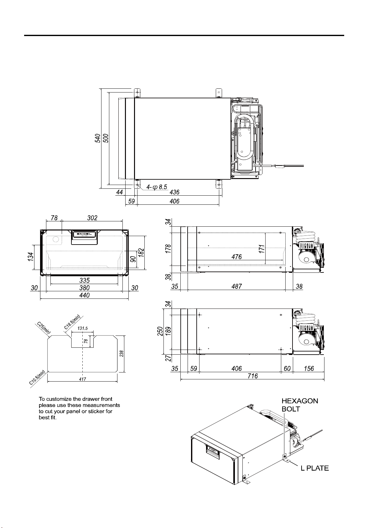
■ Dimensions ・・・・・・・・・・・・・・・・・・・・・・・・・・・・・・・・・・・・・・・・・・・・・・・・・・・・・・・・・・・・・・・・・・・・・・
2
■SB30F part name ・・・・・・・・・・・・・・・・・・・・・・・・・・・・・・・・・・・・・・・・・・・・・・・・・・・・・・・・・・・・・・・・・・・・・・
3
2. INSTALLING A REFRIGERATOR ・・・・・・・・・・・・・・・・・・・・・・・・・・・・・・・・・・・・・・・・・・・・・・・・・・・・・・・・・・・・・・・・・・・・・・
4
■ Precautions regarding the installation of the refrigerator・・・・・・・・・・・・・・・・・・・・・・・・・・・・・・・・・・・・・・・・・・・・・・・・・・・・・・・・・・・・・・・・・・・・・・
4
■ How to install the refrigerator・・・・・・・・・・・・・・・・・・・・・・・・・・・・・・・・・・・・・・・・・・・・・・・・・・・・・・・・・・・・・・・・・・・・・・
4
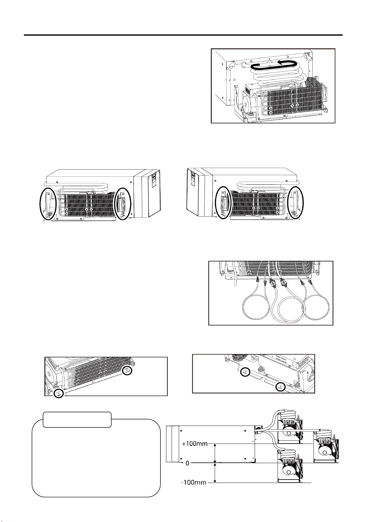
■ How to move the compressor unit・・・・・・・・・・・・・・・・・・・・・・・・・・・・・・・・・・・・・・・・・・・・・・・・・・・・・・・・・・・・・・・・・・・・・・
5
■ Notes on building in・・・・・・・・・・・・・・・・・・・・・・・・・・・・・・・・・・・・・・・・・・・・・・・・・・・・・・・・・・・・・・・・・・・・・・
7
■ Notes on free standing (not built-in)・・・・・・・・・・・・・・・・・・・・・・・・・・・・・・・・・・・・・・・・・・・・・・・・・・・・・・・・・・・・・・・・・・・・・・
8
■ About installing the machine part in another place・・・・・・・・・・・・・・・・・・・・・・・・・・・・・・・・・・・・・・・・・・・・・・・・・・・・・・・・・・・・・・・・・・・・・・
8
3 .CONNECTING DIAGRAM ・・・・・・・・・・・・・・・・・・・・・・・・・・・・・・・・・・・・・・・・・・・・・・・
9
■ Block Diagrams ・・・・・・・・・・・・・・・・・・・・・・・・・・・・・・・・・・・・・・・・・・・・・・・・・・・・・・・・・・・・・・・・・・・・・・
9
■ Wiring Diagrams ・・・・・・・・・・・・・・・・・・・・・・・・・・・・・・・・・・・・・・・・・・・・・・・・・・・・・・・・・・・・・・・・・・・・・・
9
4. TROUBLE SHOOTING ・・・・・・・・・・・・・・・・・・・・・・・・・・・・・・・・・・・・・・・・・・・・・・・・・・・・・・・・・・・・・・・・・・・・・・・・・・・
10
■ Error Display List (LED flashing) ・・・・・・・・・・・・・・・・・・・・・・・・・・・・・・・・・・・・・・・・・・・・・・・・・・・・・・・・・・・・・・・・・・・・・・
10
■ Tilt protection・・・・・・・・・・・・・・・・・・・・・・・・・・・・・・・・・・・・・・・・・・・・・・・・・・・・・・・・・・・・・・・・・・・・・・
10
■ Battery protection・・・・・・・・・・・・・・・・・・・・・・・・・・・・・・・・・・・・・・・・・・・・・・・・・・・・・・・・・・・・・・・・・・・・・・
10
■ Trouble flowchart ・・・・・・・・・・・・・・・・・・・・・・・・・・・・・・・・・・・・・・・・・・・・・・・・・・・・・・・・・・・・・・・・・・・・・・
11
●Does not get cold.・・・・・・・・・・・・・・・・・・・・・・・・・・・・・・・・・・・・・・・・・・・・・・・・・・・・・・・・・・・・・・・・・・・・・・
11
●Cooling is Weak ・・・・・・・・・・・・・・・・・・・・・・・・・・・・・・・・・・・・・・・・・・・・・・・・・・・・・・・・・・・・・・・・・・・・・・
12
●Refrigerator is too cold. ・・・・・・・・・・・・・・・・・・・・・・・・・・・・・・・・・・・・・・・・・・・・・・・・・・・・・・・・・・・・・・・・・・・・・・
13
●Compressor keeps turning on and off at short intervals. ・・・・・・・・・・・・・・・・・・・・・・・・・・・・・・・・・・・・・・・・・・・・・・・・・・・・・・・・・・・・・・・・・・・・・・
13
■ Typical Problem ・・・・・・・・・・・・・・・・・・・・・・・・・・・・・・・・・・・・・・・・・・・・・・・・・・・・・・・・・・・・・・・・・・・・・・
14
■ Technical Data ・・・・・・・・・・・・・・・・・・・・・・・・・・・・・・・・・・・・・・・・・・・・・・・・・・・・・・・・・・・・・・・・・・・・・・
14
5. CHECK POINT & CHECK METHOD ・・・・・・・・・・・・・・・・・・・・・・・・・・・・・・・・・・・・・・・・・・・・・・・・・・・・・・・・・・・・・・・・・・
15
【Check 1】Fuse. ・・・・・・・・・・・・・・・・・・・・・・・・・・・・・・・・・・・・・・・・・・・・・・・・・・・・・・・・・・・・・・・・・・・・・・
15
【Check 2】Output Voltage of the Power Supply. ・・・・・・・・・・・・・・・・・・・・・・・・・・・・・・・・・・・・・・・・・・・・・・・・・・・・・・・・・・・・・・・・・・・・・・
15
【Check 3】Resistance of the Compressor. ・・・・・・・・・・・・・・・・・・・・・・・・・・・・・・・・・・・・・・・・・・・・・・・・・・・・・・・・・・・・・・・・・・・・・・
15
【Check 4】Rated current value of compressor. ・・・・・・・・・・・・・・・・・・・・・・・・・・・・・・・・・・・・・・・・・・・・・・・・・・・・・・・・・・・・・・・・・・・・・・
16
【Check 5】Resistance of the EVA.Thermistor. (Cabinet side) ・・・・・・・・・・・・・・・・・・・・・・・・・・・・・・・・・・・・・・・・・・・・・・・・・・・・・・・・・・・・・・・・・・・・・・
16
【Check 6】Resistance of the Control Assy. ・・・・・・・・・・・・・・・・・・・・・・・・・・・・・・・・・・・・・・・・・・・・・・・・・・・・・・・・・・・・・・・・・・・・・・
16
【Check 7】Inspection between power supply and control assembly. ・・・・・・・・・・・・・・・・・・・・・・・・・・・・・・・・・・・・・・・・・・・・・・・・・・・・・・・・・・・・・・・・・・・・・・
17
【Check 8】 Inspection of fan motor. ・・・・・・・・・・・・・・・・・・・・・・・・・・・・・・・・・・・・・・・・・・・・・・・・・・・・・・・・・・・・・・・・・・・・・・
17
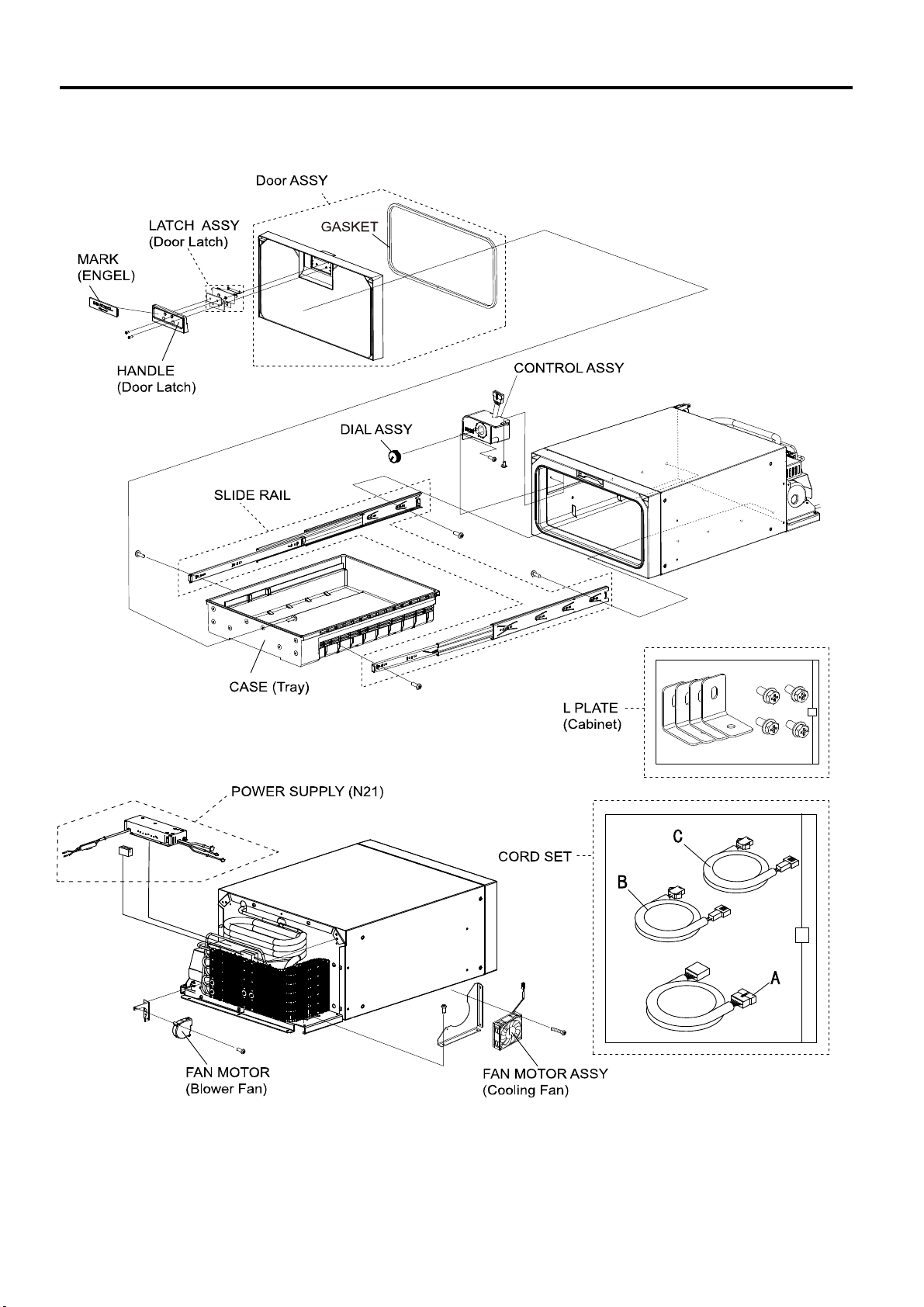
6. REPLACING PARTS ・・・・・・・・・・・・・・・・・・・・・・・・・・・・・・・・・・・・・・・・・・・・・・・・・・・・・・・・・・・・・・・・・・・・・・
18
【How to Replace Drawer & Slide Rail】 ・・・・・・・・・・・・・・・・・・・・・・・・・・・・・・・・・・・・・・・・・・・・・・・・・・・・・・・・・・・・・・・・・・・・・・
18
【Note for drawer assembly】・・・・・・・・・・・・・・・・・・・・・・・・・・・・・・・・・・・・・・・・・・・・・・・・・・・・・・・・・・・・・・・・・・・・・・
19
【How to Replace Power Supply】 ・・・・・・・・・・・・・・・・・・・・・・・・・・・・・・・・・・・・・・・・・・・・・・・・・・・・・・・・・・・・・・・・・・・・・・
20
【How to Replace Control Assy】 ・・・・・・・・・・・・・・・・・・・・・・・・・・・・・・・・・・・・・・・・・・・・・・・・・・・・・・・・・・・・・・・・・・・・・・
20
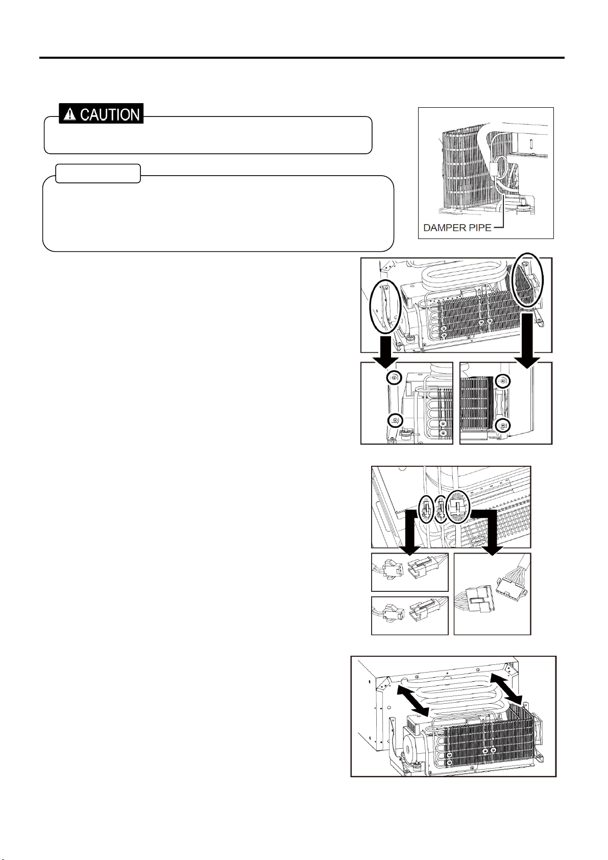
【How to Replace Fan Motor & Blower Fan】 ・・・・・・・・・・・・・・・・・・・・・・・・・・・・・・・・・・・・・・・・・・・・・・・・・・・・・・・・・・・・・・・・・・・・・・
20

■ Spec Table
SB30F-N-W
SB30F-N-U
0643 030 3210
0643 030 3220
ℓ(liter)
in
mm
mm
Case
Cover
Door
Case, inner
Evaporator
Door
Tray
Cabinet
Door
DC
DC12V/24V
LBS.
Kg
1. SPECIFICATIONS
Model
Model code
Storage volume
30
Exterior dimensions
W×D×H
17.3 × 28.2 × 9.8
440 × 716 × 250
Interior dimensions
W×D×H
Outer enclosure
Cabinet
SPCC powder coating, SGCC
ABS resin
Interior enclosure
Cabinet
Coating Aluminum
See page 3
ABS resin
Heat insulator
Foamed POLY URETHANE (CYCLOPENTANE)
Input voltage
12V / 24V
1
Refrigerant
HFC-134a
Average inside room temperature
(Dial position: "1", Ambient temp. 30℃)
8±3℃
Average inside room temperature
(Dial position: "5", Ambient temp. 30℃)
-8℃
Temperature control
Automatic temperature control by dial setting
(Electronic thermostat control type)
Weight
47.4
21.5
Rated amperage
3.4A / 1.7A
Compressor model
SK511N
Compressor rating
AC15.0V, 1.8A, 27W

■ Dimensions
● SB30F-N-/W/U
※ Tolerance is omitted Unit (mm)
1. SPECIFICATIONS
2

■SB30F part name
3
1. SPECIFICATIONS

■ Precautions regarding the installation of the refrigerator
1) Make sure to install the product horizontally.
When installing in the Vehicle or Boat, make sure the product does not install an unstable place.
2) Make sure to install the product where the air flow is available.
If the Machine parts air flow contaminated, the cooling system will degrades.
3) Avoid from direct Sunlight, Stove, or anything related to heat.
If you install the product near a gas stove, a heater, any other heat-generating appliances or place in
direct sunlight, the cooling performance is deteriorated. And there is a risk of discoloration or deformation.
4) Avoid installing the product close to a kitchen sink or water faucet.
Easily with the dew on the outer case and inner case and then installed in wet locations.
If installed in locations subject to water will damage the electrical circuits and other.
■ How to install the refrigerator
<Moving the compressor unit>
The compressor unit of this refrigerator can be placed in four different locations.
<Dimensions when the mechanical part is placed separately>
Please note that the length of the pipe varies depending on the position where it is placed separately.
2. INSTALLING A REFRIGERATOR
4
Machine part center position
(Factory position)
Installation on the left
side of the machine
Installation on the right
side of the machine
Separate
installation of
mechanical parts

■ How to move the compressor unit
① Remove the four screws with a screwdriver.
② Cut the fastener.
③ Remove the three couplers.
※Only when placed separately.
④ Separate the cabinet and compressor unit.
2. INSTALLING A REFRIGERATOR
5
It is not necessary to remove it when fixing it to the left
and right of the cabinet.
・
Be careful not to bend or crush the suction pipe.
In the unlikely event that it is damaged, the manufacturer's warranty
cannot be obtained.
・Do not move the damper pipe. (See the figure on the left)
・When working, wear gloves to avoid injury.
サーミスタ(3P)
コントロールASSY
ファンモーター
WORK TIPS

⑤ Bend the suction pipe straight and turn it in the
direction of the arrow.
⑥ Move the compressor unit to the desired side of the cabinet.
⑦ Use a screwdriver to fix the four screws and complete. (Approximately 1.18N ・ m)
※Only when the mechanical part is fixed to either the left or right side of the cabinet
Explanation when placing separately after this
⑧ Move and anchor the compressor unit in a well ventilated,
level position.
⑨ Connect the 3 extension cords sold separately.
⑩ Fix 4 screws by using a screwdriver.
2. INSTALLING A REFRIGERATOR
6
Please install the machine part on the same
plane.
If there is a difference in height, keep it
within
±100 mm.
If the height difference is larger than that,
the cooling performance will deteriorate and
it may cause a malfunction.
WORK TIPS

■ Notes on building in
<Notes on ventilation of the refrigerator>
・ Heat dissipation from the mechanical part at the rear of the refrigerator flows in the direction
of the arrow in the figure below.
・ Provide the suction port and the exhaust port as shown in the figure below so that they will not be blocked.
・The recommended opening size is 20 cm in length x 8 cm in width.
・ When built-in, change the position and orientation of the fan according to the layout of the mechanical part.
(See <Fan orientation at built-in> below)
<Fan orientation at built-in>
Change the position and orientation of the fan motor according to the following.
1) When the mechanical part is installed on
the right side of the cabinet
2) When the mechanical part is installed on
the left side of the cabinet
2. INSTALLING A REFRIGERATOR
7
If you do not change the position or orientation of the fan,
the cooling performance will deteriorate.
Change the position of the fan
Air flow
Intake vent
80mm(Min.) x 200mm(Min.) Outtake vent
80mm(Min.) x 200mm(Min.)
Failure to provide the necessary
venting will result in poor refrigeration,
continuous compressor operation,
accelerated battery discharge and
sometimes shorten the life of fridge.
WORK TIPS
WORK TIPS
Please do not change the position
or orientation of the fan.
Air flow

■ Notes on free standing (not built-in)
<Fan direction during free standing>
1) When attaching the mechanical part to the left side
when viewed from the front
2) When attaching the mechanical part to the right side when viewed from the front.
■ About installing the machine part in another place
<Air flow and fan direction>
<About the height difference when the mechanical part is placed in another place>
2. INSTALLING A REFRIGERATOR
When using the refrigerator as a free standing (not built-in) with the mechanical part attached to the left side
when viewed from the front, change the direction of the fan motor.
When using the refrigerator as a free standing (not built-in) with the mechanical part on the left when viewed
from the front, do not change the direction of the fan motor.
8
The fan label is on the outside and the
wind direction is above.
Assemble the fan inside out with the label
inside and change the wind direction
Air flow
Does not change the direction of the fan.
Does not change the direction of the fan
Please install the machine part on the same plane.
If a height difference is inevitable, keep it within ±
100 mm.
If the height difference is larger than that, the
cooling performance will deteriorate and it may
cause a malfunction.
Air flow
Outtake vent
80mm(Min.) x
200mm(Min.)
Intake vent
80mm(Min.) x
200mm(Min.)
Failure to provide the necessary venting
will result in poor refrigeration,
continuous compressor operation,
accelerated battery discharge and
sometimes shorten the life of fridge.
WORK TIPS
WORK TIPS

■ Block Diagrams
SB30F-N-W SB30F-N-U
■ Wiring Diagrams
SB30F-N-W SB30F-N-U
3 .CONNECTING DIAGRAM
9
RED
BLACK
BLACK
BLACK
RED
RED
BLACK
BLACK
BLACK
BLACK
WHIT
PURPLE
ORANGE
BLUE
BROWN
BLUE
RED

■ Error Display List (Slowly LED flashing)
If the LED is flashing, it is considered the cause of the table below.
See page
-
-
-
-
-
※It will be reset by turning off the power.
■Tilt protection
This refrigerator senses the tilt and stops.
■Battery protection
This refrigerator is equipped with a battery monitor cutting the compressor in or out in order to protect the battery.
9.6V
11.5V
20.4V
23.1V
See page17
【Check 8】
See page16
【Check 5】
10
4. TROUBLE SHOOTING
Battery voltage drop
Ambient temperature
EVA.Thermistor is abnormality
(Cabinet side)
Fixing
Charge the battery
It can not be removed from the
cooling system. Unable to fix.
Abnormal item
12V battery use
24V battery use
Overvoltage
Disconnection
Charge the battery
Test result
Lower than DC9.6V
LOW
HIGH
Compressor
Stop
Shorted
Blower Fan motor
Running
Running
0Ω
-
-
∞Ω
DC17V ~ 20.4V
More than DC32V
Ambient temperature < -20℃
Ambient temperature > 55℃
Stop
Stop
Stop
Stop
Stop
Please use DC12V or DC24V
Cut out Voltage 12V
Cut in Voltage 12V
Cut out Voltage 24V
Cut in Voltage 24V
Replace the blower fan motor
Disconnection
Replace the fan motor
Fan motor ※No LED blinking
Disconnection
Running
※Tilt protection still works when tilted in
all directions.Operating angle changes
depending on the tilt speed.
LED

No
No Yes
No
※1 Ambient temp 25℃
※2 Ambient temp 25℃~-16℃
※3 Ambient temp 30℃~0℃
4. TROUBLE SHOOTING
11
Power supply output
voltage.
(To the Compressor)
DC12V/24V
→AC15V~19V
※1
Yes
●Does not get cold.
(
No abnormality to
use power)
Is compressor
running?
DC12V→Lower than
AC15V or 0V
Checking
Are wirings and couplers
connected?
Replace the fuse.
See page 15
【Check 2】
Test result
Judge
Fixing
Connected repair.
Replace the
power supply.
AC 0V
Output
maladjustment
Is control assy
lamp lit
?
Yes
NO
Yes
Normal
The compressor is locked,
or Compressor coil is
disconnection or shorted.
Normal
Normal
Replace the
power supply.
NO
Fuse of the DC
cord is normality?
See page 15
【Check 1】
Is control assy
lamp
flashing?
Go to page 5
(■
Error
Display List
(LED flashing))
Yes
Unable to fix.
Resistance of the EVA.Thermistor.
(Cabinet side)
Approx. 2kΩ~10kΩ※2
EVA.Thermistor is broken.
∞Ω
It can not be
removed from
the cooling
system.
Unable to fix.
NO
Power supply output
voltage
.
(To the Control
assy)
DC12V
→12V
DC24V
→24V
※
1
Normal
Replace the
power supply.
DC 0V
Replace the
control assy.
Abnormality
Higher than 2.0A
The compressor is locked, or
contaminated.
Lower than 1.7A Gas is leaking.
Compressor rated current.
Approx. 1.7A~2.0A
Unable to fix
See page 16
【Check 5】
Power supply output
voltage.
(To the Compressor)
DC12V/24V
→AC15V~19V
※1
See page 15
【Check 2】
See page 17
【Check 7】

※1 Ambient temp 25℃
5. TROUBLE SHOOTING
12
●Cooling is Weak
Checking
Test result
Judge
Fixing
Battery voltage is lower than 10V
Voltage is too low.Voltage of battery 10V - 13V?
Charge the bettery
Is the machine part ventilated enough?
Make at least 150mm
room between unit and
wall.
YES
NO
Normal
Please keep the ambient
temperature below 30℃.
Ambient temperature is
too high.
Ambient temparature is higher than 30℃
NO
YES
There are too many things in the refrigerator.
Make some room
for cool air.
YES
Power supply output voltage.
Approx. AC15V - 19V ※1
Lower than AC15V
Replace the power supply.
Output maladjustment
Is the fan motor running?
NO
Fan motor is broken.
Replace the fan motor.
YES
Higher than 2.0A
The compressor is locked, or
contaminated.
Lower than 1.7A Gas is leaking.
Compressor rated current.
Approx. 1.7A~2.0A
Replace the
cooling system.
NO
Normal
See page 15
【Check 2】
Insufficient ventilation.
Cool air does not spread.
See page 17
【Check 8】
Resistance at the control assy.
Dial position 5
~OFF
Approx. 0.6kΩ~
11.5kΩ
(Resistance value changes in the
dial position.)
Replace the
control assy.
0Ω
Control assy is
shorted.
Normal
See page 16
【Check 6】

■ Trouble flowchart
※1 Ambient temp 25℃
※2 Ambient temp 25℃~-16℃
※3 Check the compressor as well, as it is possible that the power supply and compressor are failing at the same time.
13
4. TROUBLE SHOOTING
Checking
Test result
Judge
Fixing
Power supply
is broken.
Replace the
power supply.
Resistance of the EVA.Thermistor.
(Cabinet side)
Approx. 2kΩ-10kΩ ※2
EVA.Thermistor
is shorted.
0Ω
Normal
Normal
●Refrigerator is too cold.
(Can not be temperature
adjustment)
See page 16
【Check 5】
It can not be
removed from
the cooling
system.
Unable to fix.
Replace the
control assy.
0Ω
Control assy is
shorted.
Resistance at the control
assy.
Dial position 5
~OFF
Approx. 0.6kΩ~
11.5kΩ
(Resistance value changes in the
dial position.)
See page 16
【Check 6】
●
Compressor keeps turning on and off at short intervals
(2 to 3 seconds) and the refrigerator does not cool down.
YES
NO
Repeat with and
without output
The output is constant from the power supply to the compressor
according to the standard.
Power supply output voltage.
(The standard output should be constant for 30 seconds.)
Approx. AC15V - 19V ※1
YES
NO
Power supply
failure
High current
value when
there is power
supply output.
See page 15
【Check 2】
Replace the
power supply.
※3
Compressor rated current.
Approx. 1.7A - 2.0A
See page 16
【Check 4】
Replace the
cooling unit.
Compressor
failure

■ Typical Problem
Cause Treatment
* Fan motor is broken Replace fan motor
* Blower fan is broken Replace blower fan
* Ambient temparature is higher than 30℃
* Ventilation at mechanical part is not enough
See page 7
* Too many things are put inside Make some room for cool air
* Gas is leaking from cooling system Unable to fix.
* The special fuse inside DC cord is open Replace the fuse
* DC power line in the vehicle is bad Check the vehicle
■ Technical Data ※1 Ambient temp 25℃ ※2 Ambient temp 25℃ ~ -16℃
※3 Ambient temp 30℃ ~ 0℃ ※4 Tester uses the accuracy 10mΩ or less.
Checking Points Normal data See page
Dial position 5 ~ OFF
Approx. 0.6kΩ~11.5 kΩ
4. TROUBLE SHOOTING
Approx. 2KΩ ~ 10KΩ ※2
See page 15 【Check 2】
See page 15 【Check 3】
See page 16 【Check 5】
Cooling is weak
Symptoms
Checking items
DC12V/24V: Approx. AC15V~18V
※1
Does not get cold.
See page 11
Check the fuse by visual confirmation or check the
continuity with a tester.
That the fuse is not broken.
See page 15 【Check 1】
Between outgoing cords from power supply
(by ditaching from terminal of compressor)
Between two pin of the two poles coupler.
14
Lamp of temperature control
assembly is not lit.
Output voltage of power supply
Resistance of the compressor
Between incoming cords to compressor
(by detaching from terminal of compressor)
Approx. 1.23Ω ※1, ※4
Resistance of EVA.Thermistor
(Cabinet side)
See page 16 【Check 6】
Fuse
Control assy
Between two pin of the seven poles coupler.

【Check 1】Fuse (Fig.1)
◇ Check the fuse by Visual confirmation
or check the continuity with a tester.
Continuity check Judge
YES Normal
NO Broken
【Check 2】 Output Voltage of the Power Supply
◇Checking point
・Check at two poles coupler of power supply. (Fig.2)
<Use power DC12V/24V> (Ambient temp 25℃)
Test result Judge
Approx. AC15~19V Normal
AC 0 V
Approx. AC15V less than
【Check 3】 Resistance of the Compressor
◇Checking points
Measured between the terminal of the compressor.
(Fig.3)
(Ambient temp 25℃)
Test result ※1 Judge
Approx. 1.23Ω Normal
∞Ω Broken ※2
※1 Tester uses the accuracy 10mΩ or less.
※2 It can not be removed from the cooling system.
Unable to fix.
0Ω
Coil of compressor is
short circuit. ※1
15
5. CHECK POINT &CHECK METHOD
Power Supply is broken
Fig.1
Fig.3
10A FUSE
Normal Broken
Fig.2
Power Supply
Power Supply

【Check 4】Rated current value of compressor.
◇Checking points
(Ambient temp 25℃)
Judge
Normal
Compressor failure
【Check 5】Resistance of the EVA.Thermistor (Cabinet side)
◇Checking points.
Remove the two poles couplers (Fig.5-①)
(Ambient temp 25℃~-16℃)
Judge
Normal
Broken ※
Short Circuit ※
【Check 6】Resistance of the Control Assy
◇Checking points.
(Ambient temp 25℃)
Normal
Broken
Short Circuit
※Resistance value changes in the dial position.
5. CHECK POINT &CHECK METHOD
Check the resistance at between terminals brown and
blue.
Judge
Test result
Approx. 2 kΩ~10 kΩ
∞Ω
Test result
Dial position 5 ~ OFF
Measure the current value with a clamp meter on the
motor cord (Fig.4)
※It can not be removed from the cooling system.
Unable to fix.
0Ω
Check the output of the
power supply
Test result ※1
Approx. 1.7A~2.0A
1.7A or less or 2.0A or more
0A
16
Approx. 0.6kΩ~11.5 kΩ
∞Ω
0Ω
Fig.5
Black & Black
BLUE
BROWN
Fig.6
Fig.4

【Check 7】Inspection between power supply and control assembly.
1.<Voltage from power supply to control assembly>
◇Checking points.
Voltage measurement in RED (+) and BLACK (-)
(Fig.7) (Ambient temp 25℃)
Judge
2.<Voltage from control assembly to power supply>
◇Checking points.
Voltage measurement in ORANGE (+) and BLACK (-)
(Fig.7) (Ambient temp 25℃)
Judge
【Check 8】 Inspection of fan motor
◇Checking point
If want to check the start-up of the fan motor directly,
can check by connecting the DC12V directly. (Fig.8)
Judge
5. CHECK POINT &CHECK METHOD
Test result
Fan moter broken
Does not move or rotates
slowly
Test result
At DC12V = DC12V
Normal
At DC24V = DC24V
Different from the above voltage
Power Supply is broken
0V
17
Test result
At DC12V = DC12V
Normal
At DC24V = DC24V
Different from the above voltage
Control assembly broken
0V
Fig.7
Fig.8
Blower Fan
Cooling Fan
・Please be careful not to mistake the polarity of the
power supply.
・When connect with DC24V or wrong polarity,
fan motor will fail.
・Please use such as support coupler so as not to
short-circuit power.
This manual suits for next models
3
Table of contents
Other SAWAFUJI ELECTRIC Refrigerator manuals

SAWAFUJI ELECTRIC
SAWAFUJI ELECTRIC Engel MT17F-U1 User manual

SAWAFUJI ELECTRIC
SAWAFUJI ELECTRIC Engel SB30F-N-A User manual

SAWAFUJI ELECTRIC
SAWAFUJI ELECTRIC Engel MT17F-U1 User manual

SAWAFUJI ELECTRIC
SAWAFUJI ELECTRIC Engel MT45F-G4NCD-V User manual

SAWAFUJI ELECTRIC
SAWAFUJI ELECTRIC ENGEL MT35F-G4-P User manual

SAWAFUJI ELECTRIC
SAWAFUJI ELECTRIC Engel MT35F-U1 User manual

SAWAFUJI ELECTRIC
SAWAFUJI ELECTRIC ENGEL MT Series User manual

SAWAFUJI ELECTRIC
SAWAFUJI ELECTRIC Engel SB Series User manual