SAY Security Group DVW-KBD-D User manual

Installation & Operation Manual
DVW-KBD-D Universal Keyboard
CONTENTS
Section Page
Connecting the Keyboard .............................................. ............. 2
Switch settings .............................................................................. 3
Programming and operation.........................................................5
Keyboard functions........................................................................6
Scanning functions.........................................................................8
Programming limit stops...............................................................8
Specifications................................................................................. 9
- 1 -

INSTALLATION
The keyboard is wired directly to a maximum of 16 receivers. You can
communicate using Pelco P Protocol or Pelco D Protocol.
In Direct P and Direct D modes you can now change the zoom speed of a
PTZ by entering a number from 1 to 4 followed by a zoom command. This
causes the zoom speed command to be sent.
Connecting the Keyboard
1. Make sure all receivers are configured to communicate using either Pelco
P or Pelco D protocol and that each receiver has a unique address. Refer
to your receiver manual for switch settings.
2. Decide on a suitable location for the keyboard and wall block. The
keyboard must be within 25 feet (7.6 meters) of the wall block. The wall
block must be within 6 feet (1.8 m) of the nearest suitable electrical outlet.
Do not mount the wall block at this time.
3. Receiver wiring should be in place before installing the keyboard. You
can control up to 16 receivers from the keyboard. Communication to the
keyboards is RS-422. Maximum cable distance for RS-422
communication over 24-gauge wire is 4,000 feet (1,219m). The
recommends using shielded twisted pairs cable that meets or exceeds the
basic requirements for EIA RS-422 applications.
4. Remove the wall block cover and make receiver cable connections.
- 2 -

5. At the wall block wire the transformer to pins 3 and 4. Polarity is
unimportant.
6. Replace the cover on the wall block. A double-sided sticky pad is
provided to mount the wall block. Secure the wall block to a suitable
surface.
7. Set the keyboard DIP switches according to the instructions in the Switch
Settings section.
8. Plug in the keyboard data cable.
9. Plug the DVW-KBD-D transformer into a suitable outlet. The LED
display shows number 1, which is the default camera number.
10.Go to the Programming and Operation section and program and test for
proper operation
SWITCH SETTINGS
To set the switches on the keyboard (refer to Figure 12):
1. Remove the two screws and the DIP switch cover plate from the rear
of the keyboard.
2. Set the switches:
Address (Switches 1-4) Position the switches according to Table A.
Each keyboard in the system must have a different address, including
- 3 -

the local keyboard. To make programming easier, address keyboards in
ascending order
Table A. Keyboard Addresses
Keyboard Switch settings
1
234
1 OFF OFF OFF OFF
2 ON OFF OFF OFF
3 OFF ON OFF OFF
4 ON ON OFF OFF
5 OFF ON ON OFF
6 ON OFF ON OFF
7 OFF ON ON OFF
8 ON ON ON OFF
9 OFF OFF OFF OFF
10 ON OFF OFF ON
11 OFF ON OFF ON
12 ON OFF OFF ON
13 OFF OFF ON ON
14 ON OFF ON ON
15 OFF ON ON ON
16 ON ON ON ON
Mode (Switches 5, 7, 8) Position the switches according to Table B.
Switch 6 enables/disables turbo pan. It can be switched while the
keyboard is on.
Table B. Keyboard Modes
Direct P Direct D
Switch 5 ON ON
Switch 6 ON or OFF ON or OFF
Switch 7 OFF ON
Switch 8 OFF OFF
- 4 -

PROGRAMMING AND OPERATION
Table C. Keyboard Functions
Function Procedure
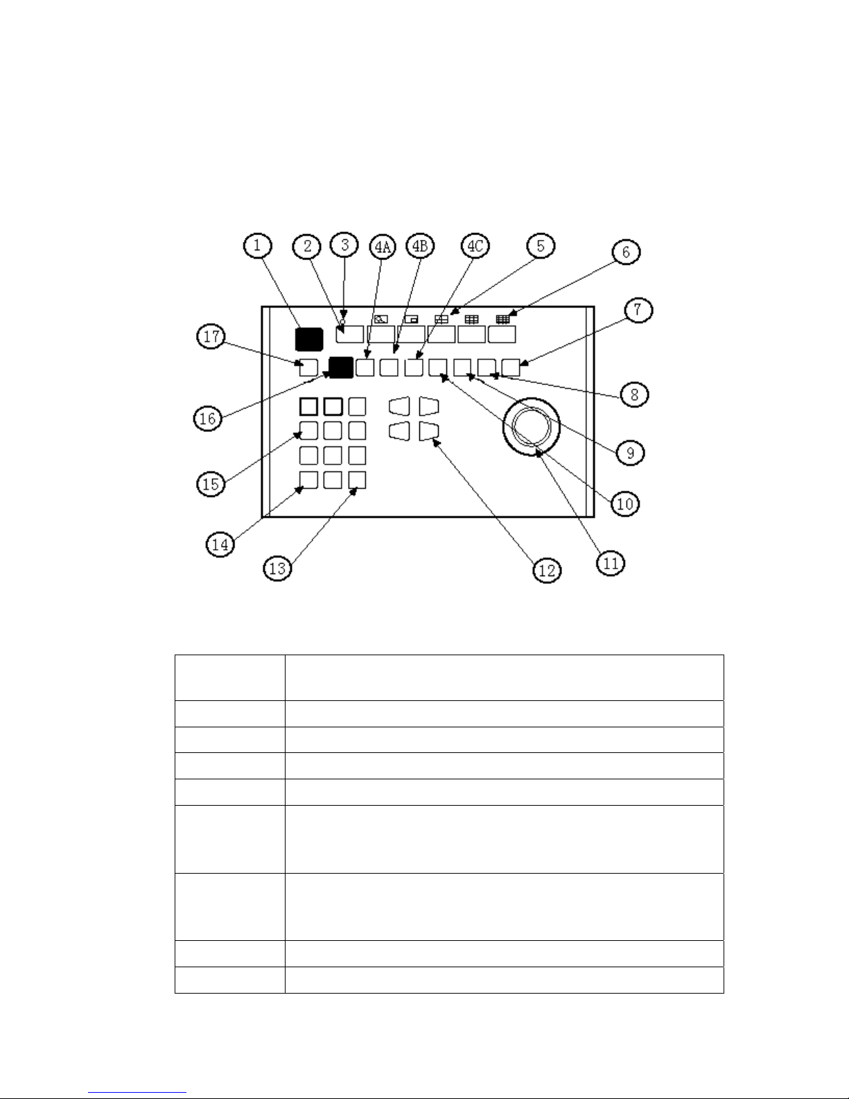
Select Camera Enter camera number (1-16) and press CAM to select.
Pan/Tilt/Zoom Move the joystick until the camera reaches the desired
position. To increase the speed of movement, move the
joystick further from center.
Twist the joystick clock wise to zoom in, counterclockwise
to zoom out.
Lens Control Focus, iris - Press and hold the appropriate lens control key
until the desired effect is seen.
Presets Enter preset number (1-66) and press PRESET to put
camera in preset position.
To program, position camera, enter desired preset number
(1-66), and hold down PRESET for two seconds.
Table C Keyboard Functions (continued)
Function Procedure
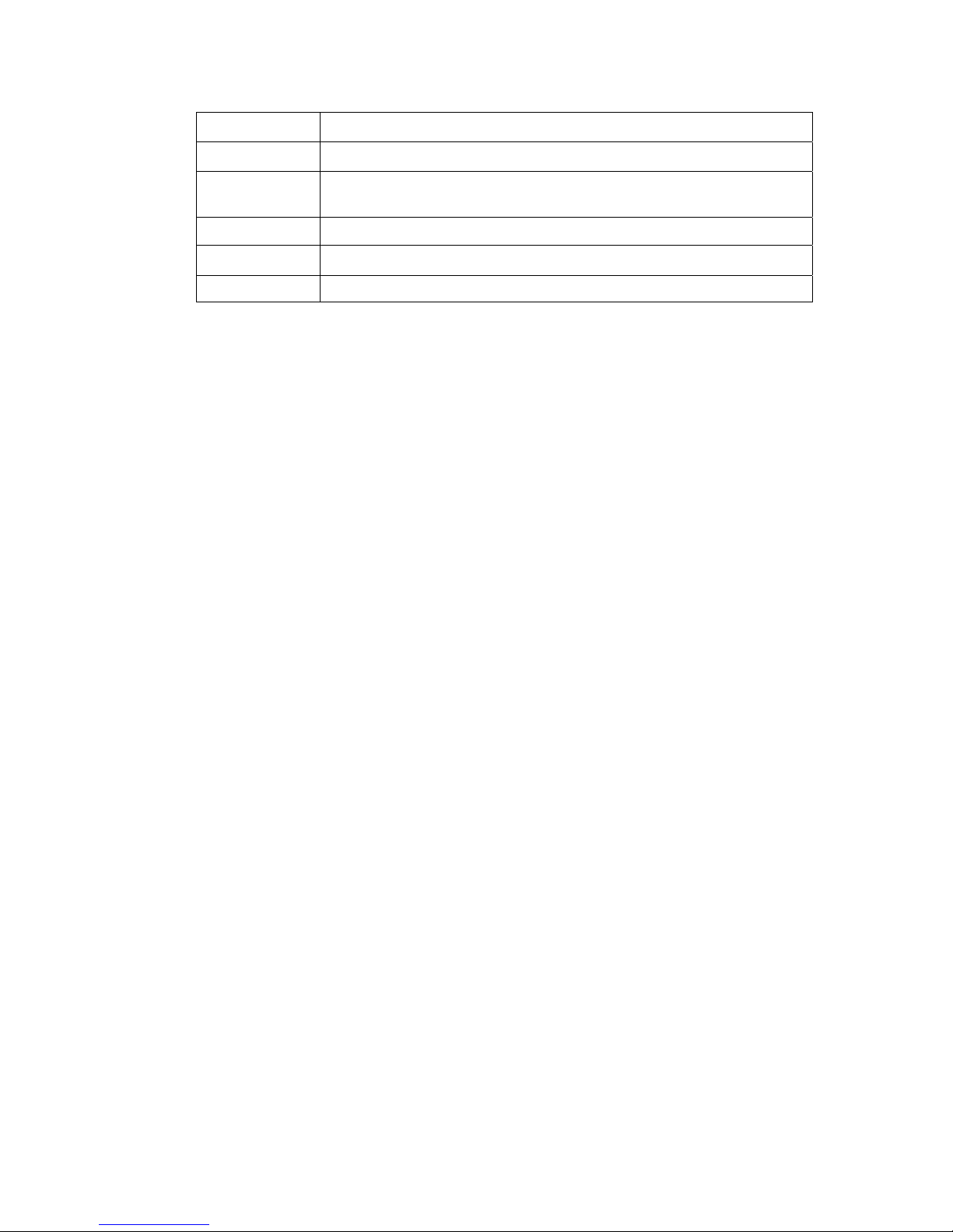
Patterns Programming and operation varies with the receiver type. To
program DVW-D, select a camera (1-16), select a long pattern
by holding down PATTERN for two seconds, or select short
pattern 1 or 2 by entering 1 or 2 and holding down PATTERN
for two seconds. The monitor will indicate the programming
function is active. Move the camera position _ as desired for the
pattern and press ACK to close the programming function.
To run a long pattern, press PATTERN. To run a short pattern,
enter 1 or 2 and press PATTERN. Move the joystick or call a
preset to stop.
Do not program a pattern with turbo pan on (switch 6).
- 5 -

KEYBOARD FUNCTIONS
Table D. DVW-KBD-D Button Functions
Reference
Number
Description
1 LED display
2 Shift key
3 Shift key LED
4 Sequence keys: Previous, Next, Hold
5 Function keys F1/Latch, F2/Off, F3/Mom control
auxiliaries.
With Shift on they control multiplexer display.
6 The AUX ON and AUX OFF keys control receiver
auxiliaries.
With Shift on they control multiplexer display.
7 Program key
8 Preset key
- 6 -

9 Pattern key
10 Joystick
11 Focus and iris keys (iris keys can be used to scroll through
menus on the CM6800 only)
12 Camera selection key
13 Keypad (numbers 1 through 0)
14 Acknowledge key
Operation of the scanning functions depends on the kind of receiver or
pan/tilt mechanism you have and the operating mode of your keyboard,
There are four types of scanning functions: auto (moves camera back and
forth between stops), random (moves camera in a random pattern), frame
(moves camera back and forth in 10 degree steps), and preset (sequences
camera through all programmed presets, pausing between each).
Operate scans according to Table E.
- 7 -

SCANNING FUNCTONS
Table E Operating scan Functions with Various Receivers
AUTO SCAN RANDOM SCAN FRAME SCAN STOP SCAN
99 preset 97 preset 98 preset 96 preset
Programming Limit Stops
Spectra and Esprit can be programmed for scan and manual limit stops.
Program left limit before programming right limit. Locate camera at
desired limit. Enter the set code from Table G. Hold the PRESET key for
two seconds. In CM6700 and CM6800 modes, a label appears on the
monitor. Use F1 and F2 to edit the label, then select SET and press ACK or
tap the joystick to the right and release.
To cancel all limit stops, enter 95. Hold the preset key for two seconds.
Move joystick up or down to move the pointer to Other. Press IRIS OPEN.
Move the pointer to Limit Stops. Press IRIS OPEN. Move joystick right/left
to change limit stops to off. Press IRIS OPEN. Move the pointer to EXIT.
Press IRIS OPEN.
Move pointer to exit. Press IRIS OPEN.
Table F. Limit Set Codes
Scam Limit Manual Limit
Left Limit 92 90
Right Limit 93 91
- 8 -

SPECIFICATIONS GENERAL
Keyboard Keypad: Electromechanical
Joystick: 3-axis, vector-solving, with twisting, return-to-center head
Digital Display: Red LED, 7-segment, 2 cells
Shift Mode Indicator: Green LED Ambient Operating
Temperature: 20 to 120 F (-7 to 49 C)
Humidity: 10–90% non-condensing
Dimensions: 9.50(W) x 7.125(D) x 2.25(H) inches (24.13 x 18.1 x 5.72cm)
Weight: 2.5 lb (1.12 kg)
Ratings: Meets NEMA Type 1 standards
Meets IP 30 standards
ELECTRICAL
Input Voltage: 12 VAC or 12 VDC
Power Consumption: 5 watts
Connector Type: RJ-45, 8-pin, modular (female)
Keyboard Communication Direct D Mode
Interface: RS-485
Protocol: Pelco D
Baud: 2400 Communication
Parameters: 8 data bits, 1 stop bit, no parity
(Design and product specifications subject to change without notice)
- 9 -
Table of contents