Wincor Nixdorf TA59 User manual

TA59
Keyboard
Product Manual
Edition November 2004

Copyright © Wincor Nixdorf International GmbH, 2004
The reproduction, transmission or use of this document or its contents is not
permitted without express authority.
Offenders will be liable for damages.All rights, including rights created by pa-
tent grant or registration of a utility model or design, are reserved.
Delivery subject to availability; technical modifications possible.
Pentium ™ is a registered trademark of Intel Corporation
Linux ™ is a registered trademark of Linus Torvalds
MS-DOS ©, Windows 95, Windows 98SE, Windows 2000Pro and Windows
NT are registered trademarks of the Microsoft Corporation
BEETLE® is a registered trademark of the Wincor Nixdorf International
GmbH

Contents
Manufacturer’s Declaration and Approval ........................1
General Authorization .................................................................................1
TFCC-Class A Declaration..........................................................................1
Recycling the TA59.....................................................................................2
Warranty .....................................................................................................3
Safety Instructions ......................................................................................3
Cleaning Instructions ..................................................................................4
Scope of supply ..........................................................................................4
Mounting keys .....................................................................5
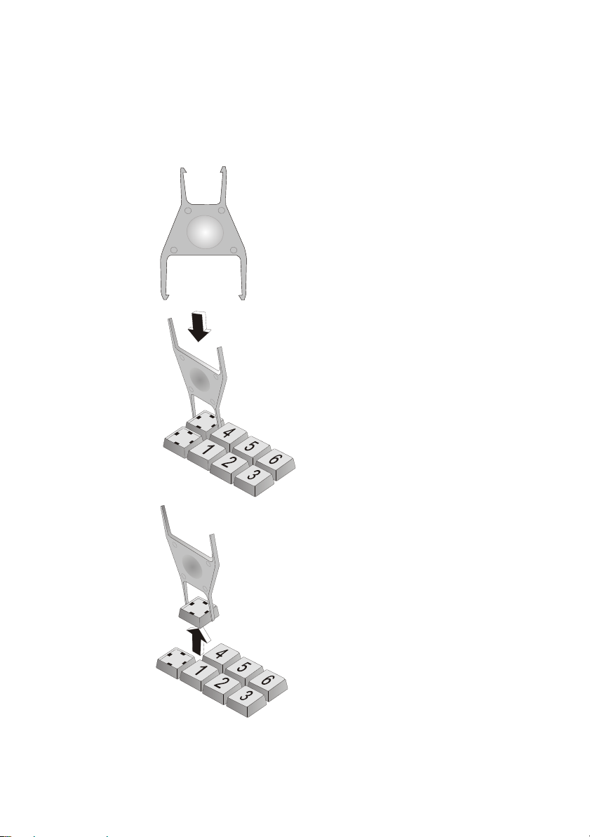
Exchanging the Keys ..................................................................................5
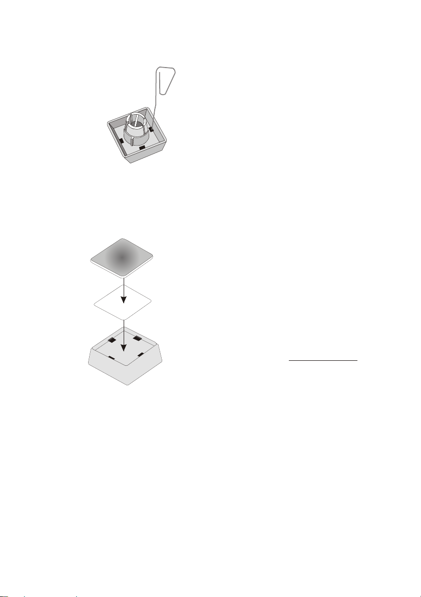
Inserting Key Labels ...................................................................................6
Inserting Key Caps......................................................................................7
The TA59 Keyboard.............................................................8
General .......................................................................................................8
Keypads......................................................................................................9
Self-test.....................................................................................................10
Connection method...........................................................11
Releasing the Cable Connection...............................................................11
Key switch..........................................................................12
Magnetic Stripe Card Reader (optional) ..........................13
Using the magnetic stripe card reader ......................................................13
Touchpad (optional) ..........................................................14
Operating .................................................................................................14
Programming the TA59 .....................................................15
Modes .......................................................................................................15
Main functions of the Programs ................................................................16
Keyboard Connection for Programming ....................................................17
Keyboard connection in the field .........................................................18
Firmware Update and Version Display......................................................18
Help ..........................................................................................................19
Creating Tables with KBUTI.EXE..............................................................19

Sending and Receiving Tables .................................................................21
Files for Programming...............................................................................21
Useful hints ...............................................................................................22
Keyboard Layout ...............................................................23
International Layout (e.g. Germany) .........................................................23
US Layout .................................................................................................24
Keyboard Scan Codes - Table 1 ...............................................................25
Keyboard Scan Codes - Table 2 ...............................................................26
Keyboard Scan Codes - Table 3 ...............................................................27
Appendix ............................................................................28
Technical Data..........................................................................................28
Magnetic Stripe Card Reader....................................................................29

Manufacturer’s Declaration and Approval
General Authorization
This device fulfills the requirements of the EEC standards
89/336/EEC “Electromagnetic Compatibility” and 73/23/EEC
“Low voltage Directive”.
Therefore, you will find the CE mark on the device or packaging.
TFCC-Class A Declaration
This equipment has been tested and found to comply with the limits for a
Class A digital device, pursuant to part 15 of the FCC Rules. These limits
are designed to provide reasonable protection against harmful interference
when the equipment is operated in a commercial environment. This
equipment generates, uses, and can radiate radio frequency energy and, if
not installed and used in accordance with the instruction manual, may cause
harmful interference to radio communications.
Operation of this equipment in a residential area is likely to cause harmful
interference in which case the user will be required to correct the
interference at his own expense.
Modifications not authorized by the manufacturer may void users authority
to operate this device.
This class A digital apparatus complies with Canadian ICES-003.
Cet appareil numerique de la classe A est conforme a la norme NMB-003
du Canada.
1
GENERAL AUTHORIZATION

Recycling the TA59
Environmental protection does not begin when it comes
time to dispose of the TA59; it begins with the
manufacturer. This product was designed according to
our internal norm “Environmental conscious product
design and development”.
The TA59 is manufactured without the use of CFCs und CCHS and is
produced mainly from reusable components and materials.
The processed plastics can, for the most part, be recycled. Even the
precious metals can be recovered, thus saving energy and costly raw
materials.
Please do not stick labels onto plastic case parts. This would help us to
re-use components and material.
You can protect our environment by only switching on your equipment when
it is actually needed. If possible, even avoid the stand-by-mode as this
wastes energy, too. Also switch your equipment off when you take a longer
break or finish your work.
At this time, there are still some parts that are not reusable. Wincor Nixdorf
guarantees the environmentally safe disposal of these parts in the
Recycling Center, which is certified pursuant to ISO 9001 and 14001.
So don’t simply throw your TA59 on the scrap heap when it has served its
time, but take advantage of the environmentally smart, up-to-date recycling
methods!
Please contact your competent branch or the Recycling Center Paderborn
(for European countries) for information on how to return and re-use devices
and disposable materials under the following fax number:
E-Mail: info@wincor-nixdorf.com
We look forward to your message.
RECYCLING THE TA59
2

Warranty
Wincor Nixdorf guarantees generally a warranty engagement for 12 months
beginning with the date of delivery. This warranty engagement covers all
those damages which occur despite a normal use of the product.
Damages because of
nimproper or insufficient maintenance,
nimproper use of the product or unauthorized modifications of the product,
ninadequate location or surroundings
will not be covered by the warranty.
For further information of the stipulation look at your contract.
All parts of the product which are subject to wear and tear are not included
in the warranty engagement.
Please order spare parts at the Wincor Nixdorf customer service.
Safety Instructions
Note the following safety information:
nLay all cables and supply lines so that nobody can tread on them or trip
over them.
nData cables should be neither connected nor removed during
thunderstorms.
nProtect the device from dust, moisture and heat.
nTake care to ensure that no foreign objects (e.g. paper clips) or liquids
can get into the inside of the device, as this could cause electrical shocks
or damage.
nPlace the keyboard on a non-slip, even surface.
3
WARRANTY

Cleaning Instructions
The keyboard should be cleaned with a germicide from time to time. Before
cleaning in between the keys with a brush, loosen and remove the key caps
using the key removing device. Do not allow dust to get in through the open
keyboard mechanics.
Scope of supply
The product includes one TA59 keyboard, one User Guide and one
accessories kit containing the following:
nTransparent plates
nBlank sheets for labeling
n1 key cap remover
n1 set of keys for key switch
The set of keys contains:
Key 1 for key position 1
Key 2 for key positions 1 and 2
Key 3 for key positions 1, 2 and 3
Key 4 for key positions 1, 2, 3 and 4
The following items can be ordered optionally:
Accessories kit 1:
20 dummy keys (1 x 1)
Accessories kit 2:
6 double key caps
2 quadruple key caps
If damage has occurred during shipping or if the package contents do not
match the delivery note, promptly notify your Wincor Nixdorf sales outlet.
CLEANING INSTRUCTIONS
4

Mounting keys
Exchanging the Keys
You can remove each of the key
caps using a key cap remover,
pulling the key upwards.
Place the key cap remover on
the selected key until you hear a
click.
Now remove this key from the
keyboard by pulling upwards.
5
EXCHANGING THE KEYS

You can change the lettering as follows:
Using a thin object (e.g.
Paper-clip etc.), press upwards
against the plastic cover through
the opening on the underside of
the key. Please refer to the next
chapter for instructions on how to
insert the new label.
Inserting Key Labels
Below, you will find instructions on how to insert the key labels:
Each key should be labelled
individually.
Place the written label on the key
cap.
Insert the transparent key cover
with the mat and concave side
upwards until it clicks into place
in the key cap.
The labels are replaced as follows:
nRemove the key cap from the keyboard (see removing the key cap) and
pull the transparent key cap upwards.
nThe transparent key cover is then released and the label can be removed.
nReplace the label and fit the transparent key cover (with the mat and
concave side facing upwards) back into the key cap.
INSERTING KEY LABELS
6
Label for keys
Transparent key cover
with mat and
concave side up
Key cap

Inserting Key Caps
Insert the key cap in the keyboard and press firmly into place.
When inserting double keys,
please ensure that the guide
cylinder is on the left with a
horizontal arrangement and on
the top with vertical arrangement.
The quadruple key caps are corresponding - with the guide cylinder
arranged on the upper left. The position of the guide cylinder specifies the
key code.
Ensure while putting on the key
caps that the white cam of the
rocker plate are in the planned
bulge of the keyboard.
If you hear a click, the key caps
are inserted correctly.
quadruple key cap with scissors
7
INSERTING KEY CAPS
cam
rocker plate

The TA59 Keyboard
General
The alphanumeric keyboard TA59 is equipped with a central keylock and
optionally with a magnetic stripe card reader or a touchpad. The keypad
without touchpad consists of 137 keys (136 keys in the US version), the
keypad with touchpad consists of 125 keys (124 keys in the US version).
Unlike other standard PC keyboards, the TA59 has a flexible key layout,
e.g. several keys can be grouped vertically or horizontally to form double or
quadruple keys. Only one key code is generated by each multiple key.
Keyboard TA59 (with magnetic stripe card reader and touchpad)
GENERAL
8

Keypads
The TA59 keyboard differs from standard PC keyboards by virtue of its
multiple function key concept. This concept permits a flexible key layout, i.e.
double or quadruple keys can be used on the TA59. This is possible in the
following keypads:
nIn the upper row of function keys;
nIn the keypad to the right of the numeric keypad.
Only one key code is transmitted by each multiple key.
Only one key code is generated by each double or quadruple key. Different
key codes can be set for the multiple keys by rotating the key caps. These
caps have a guide cylinder that is shifted when the cap is rotated, resulting
in different key codes. This will lead to problems if not observed
(see page 7).
Incorrect key caps on the TA59 keyboard can be changed on the spot.
Dummy caps can also be used. The keyboard is divided into 5 keypads:
nAlphanumeric keypad keys
nFunction key keypad 1
nNumeric keypad
nFunction key keypad 2
nFunction key keypad 3
KEYPADS
9

N* Numeric Keypad
Self-test
A self-test is performed each time the POS terminal is switched on. The
result of the test is reported to the system.
SELF-TEST
10
d
apyek
ci
re
m
u
nahplA
2+
1d
apye
ky
ek
no
itcn
uF
3da
pye
k
ye
k
no
itcnuF
*N

Connection method
The connector for the keyboard is a standard 6-pin mini-DIN connector.
Releasing the Cable Connection
Never remove a cable from a connector socket by simply pulling on the
cable. Always remove the cable by the connector housing. Please follow the
instructions below when removing cables:
nTurn off all switches to the mains and electrical equipment.
nRemove all mains cables from the shockproof sockets installed in the
building.
nLoosen all cables on the electrical equipment.
Using your thumb and forefinger,
pull gently on plastic connector
housing. Removing the
connector from the socket. This
unlocks the connector.
Now remove the connector from
the socket.
11
RELEASING THE CABLE CONNECTION

Key switch
The TA59 keyboard is equipped with a key switch with 5 switch positions.
Switch position 0 is the basic position; switch positions 1-4 are provided for
customer-specific applications. In positions 0 and 1, the key can be
removed.
The switch position on the lock
by T is intended for use by Field
Engineering. From switch
position 0, the key provided can
be turned to position T only. This
key is not included in the scope
of supply.
The key switch has only one
closure, i.e. there is only one set
of keys for all keylocks that
includes the above-mentioned
key variants for the various
switch positions.
KEY SWITCH
12
00
11
22
33
44
TT

Magnetic Stripe Card Reader (optional)
The TA59 can also be equipped with a magnetic stripe card reader (option)
which can be used to read up to three tracks simultaneously each time a
card is pulled through.
Using the magnetic stripe card reader
Pull the magnetic card evenly and quickly, from right to left, through the slot
on the magnetic stripe card reader. Make sure that the magnetic stripe is
facing the keys.
Note the following precautions when handling magnetic cards:
nNever allow magnetic cards to come into contact with liquids.
nNever bend or fold magnetic cards.
nNever expose magnetic cards to a magnetic field.
Insert the magnetic card in the special slot provided on the reader from the
right-hand side only; inserting the card at another location could damage the
read heads.
In order to ensure that the quality of reading results is maintained, clean the
magnetic stripe card reader at least once a week. To do this, use the
special cleaning card that can be ordered from Wincor Nixdorf.
13
USING THE MAGNETIC STRIPE CARD READER

Touchpad (optional)
The touchpad replaces the mouse and is appropiate when there is lack of
space for using a mouse. The touchpad takes over the functions of a mouse
and is operated with the finger.
Do not press on the touchpad with a hard or a sharp object like e.g. a ball
point pen. The touchpad could be damaged.
Do not contaminate the touchpad with dirt like liquids or grease.
Do not put heavy objects on the touchpad, the control buttons or keyboard.
Operating
The touchpad requires a pointer such as a finger. To use the Touchpad,
simply move your finger tip across the surface in the direction of the screen
pointer.
The left mouse button is released by a shortly tapping on the pad. Double-
tapping corresponds to a double click of the left mouse button. You receive
the Drag and Drop function by selecting the object, leaving the finger on the
pad, moving the object and dropping it into the new position.
The control buttons below are used like the left or right mouse button. Press
the left button to position the cursor and press the right mouse to display the
context menu.
The touchpad works only under a BEETLE system from D2-CPU upwards.
It does not work under former versions, e.g. C1, C2, D1.
OPERATING
14
PAD Control Buttons

Programming the TA59
By programming the TA59 you have the possibility to flexibly adjust the
keyboard to your special needs.
You can
ndesign the keyboard layout according to your needs by - for example -
moving the numeric block to any place on the keyboard,
ndefine several levels for the keycodes, thus using the same key as a
functional key on one level and for text input on another level,
ndefine header and trailer for each data track of MSR-controller and for
keylockswitch,
nport your existing software application with less effort, as you can keep up
the key codes.
Modes
The TA59 keyboard works in different modes:
“Windows Mode” This is the default state of the keyboard (not
programmed)
“DOS Mode” This state is used by the Retail Device Interface
(RDI), it is entered by rsp. commands from Windows
Mode
“Programmed” In this state a table has been sent to the keyboard and
is stored in Flash memory; the table controls what
codes are sent for keys and for the component key
lock
Moreover there are mixed modes possible:
“Programmed” for the keys
“Windows” rsp. for the component key lock
“DOS-Mode”
15
MODES

The DOS Mode is primarily used by RDI, the Windows Mode is used by the
OPOS components. A description of this protocol can be sent to you by
Wincor Nixdorf on request. When developing new software you should
generally use the Windows Mode.
Main functions of the Programs
The dialogue utility KBUTI.EXE serves to:
nprogram the codes for the keys and the component key lock
nsend a keyboard table to the keyboard
nreceive a table from the keyboard and to store it in a file
nreset a keyboard into its default state, i.e. Windows Mode and default
codes for the keys
ncheck for keyboard state (default or programmed)
ncheck release no. of loader and firmware module (data, version,
modulsize..)
nupgrade firmware module (KBUTI.EXE version 1.20 and higher)
So the functionality of the programs
nSENDKBT.EXE
nRCVKBT.EXE
nKB2DEF.EXE
nKBCHKDEF.EXE
is part of the dialogue utility. These 4 programs therefore are intended to be
used in conjunction with .BAT files. They return values that can be checked
using ERRORLEVEL. The values returned together with an example you
will find in the Readme file.
Files containing keyboard tables for TA59 have the extension .KBT. Files
containing a firmware upgrade module have the extension .FRM.
MAIN FUNCTIONS OF THE PROGRAMS
16
Table of contents
Other Wincor Nixdorf Keyboard manuals
Popular Keyboard manuals by other brands

Man & Machine
Man & Machine CoolMIR BlackBerry Keyboard User and installation manual

SteelSeries
SteelSeries APEX PRO MINI Product information guide

DynaVox
DynaVox DYNAwrite reference guide

Mazi
Mazi CA-101 user manual

SteelSeries
SteelSeries APEX PRO TKL Product information guide

PCD Maltron
PCD Maltron RS10N1G-UK user manual