MDVR Manual
More info
mation www.mobilewitness.com
3
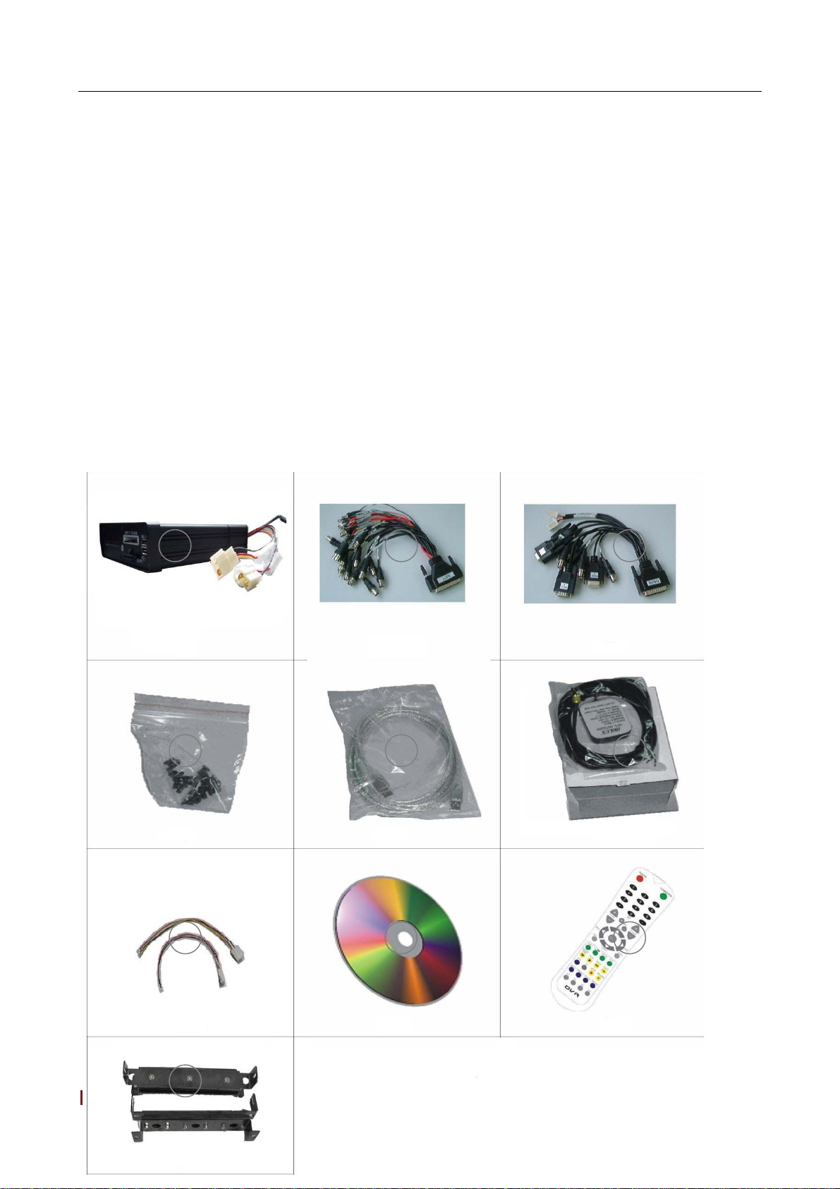
I. Product Components and Features
System Recording Module and Mounting Assembly
zUltra compact case, extremely low weight, high temperature resistance, and vibration resistant
zQuick-Release removable Recording Module with tamperproof lock and secure controls
zFlexible Mounting Assembly for permanent connection to vehicle or permanent installation
zIndividual wire connections for audio, video, power, inputs/outputs, and accessory assemblies
z12v, 3Amp regulated power for use with cameras, inputs/outputs, and accessory assemblies
zFull support for NTSC or PAL video inputs and outputs, audio channels, VGAdisplay
zCommunications supported through TCP/IP network interface and USB connection to PCs
zHand-held, IR controller with On-Screen Display (OSD) for all operations of the MDVR
z2.5-in. mobile anti-vibration and shock resistance HDD
Video and Audio MDVR Features and Capabilities
z4 channels for video input, full-motion (30FPS/camera) continuous or priority video recording and live display
z4 channels for high-fidelity, digitally recorded, synchronized audio matched to 8 video channels
zContinuous recording while in the playback mode
zUser friendly criteria to playback the events associated video only
zAutomatic timer to resume the live display if the unit is idle for user defined timings
zMPEG-4 video compression for high quality, low storage recording and playback
zUser-selectable settings for quality and audio record enable/disable for each video channel
z12v power supply for multiple devices such as cameras, sensors, relays and any other accessories
zSelectable frame rate with event-triggered burst recording speeds up to 30FPS/camera
zMultiple alarm inputs with selectable pre-alarm and post-alarm record timings
zTV output channel for live video and recorded video viewing
Streaming Video Output for Multimedia Contents
zDVD-quality streaming audio/video with NTSC or PAL composite or VGA output
zFlash card, USB, Network media update
zIndependent operation of MDVR and streaming advertising simultaneously
Remote Connection Capabilities
zHandheld Infra-Red controller with OSD for quick access to recorded video and settings menus
z2 USB connection for file transfer, PC-based file transfer and settings management
zPC-Based Client software for live viewing, playback video, playback events associated video, and download
capabilities
zSupport CMS (Central Monitoring System), Auto download program (Wireless from WiFi), RMS (Remote
Management Software) program, Playback Analysis Program
Accessory Modules for MDVR
zVideo Interface Module including GPS location and speed
zVehicle Motion Manager includes 3-axis Inertia Sensor to determine video-matched motion events
zVideo event search allows intelligent searching of recorded video based on event logs
zControl panel for operation. (Optional)