Mounting Instructions
The Q.RCU-D-xx sensors have been specially designed for easy
installation. However, certain conditions apply when choosing a
suitable location for the device:
- The device should not be installed on an exterior wall.
- The device should not be installed near a heat source.
- The device should not be installed near an air discharge grill.
- The device should not be installed in a place where it can be
aected by the sun.
- Install the device in an area that provides proper device
ventilation. Nothing must restrain air circulation to the device.
The Q.RCU-D-xx sensor has not been designed for out-
door use.
Installation Procedure
1. Remove the security screw from the device.
2. Open the Q.RCU-D-xx sensor by pushing in the tab on the bottom
of the device and pulling the bottom side of the front plate out.
3. Open The Q.RCU-D-L Light/Blind module by pulling the front
plate o (if applicable).
4. Plug the Q.RCU-D-L Light/Blind add-on modules into the back
plate (if applicable).
5. Make sure that the mounting surface is at and clean.
6. Align the back plate with the wall and mark the location of the
mounting holes on the wall (2 holes for the sensor and 1 hole per
Q.RCU-D-L Light/Blind module are recommended). Make sure to
orient the proper side of the back plate facing upwards.
7. Remove the back plate and drill holes in the wall if necessary.
8. Install anchors in the wall if necessary.
9. Unplug the Q.RCU-D-L Light/Blind add-on modules from the
back plate (if applicable).
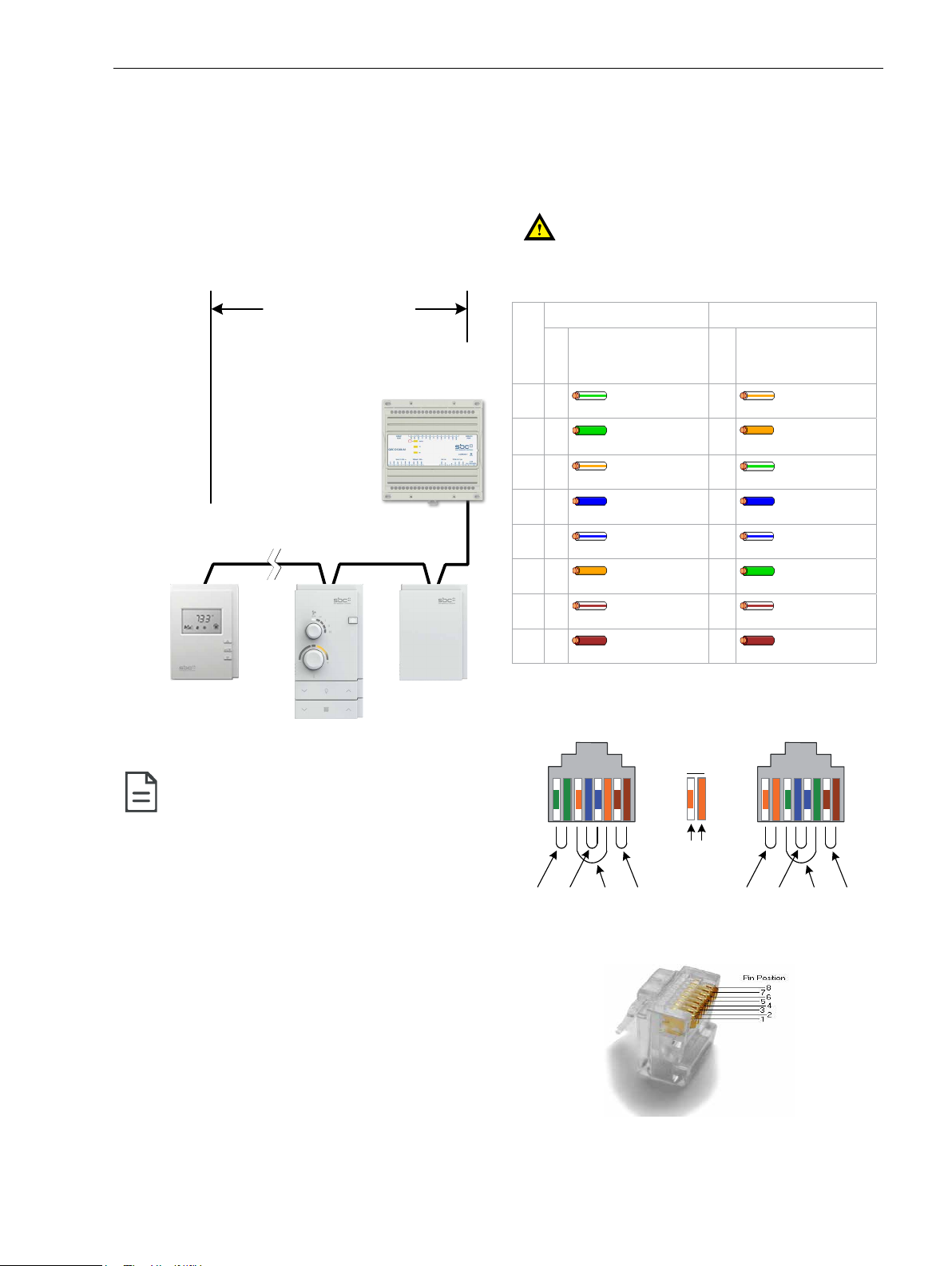
10. Pull all RJ-45 cables and digital wires (if applicable) 15 cm (6”)
out of the wall, and insert them through the central hole of the
back plate.
11. Screw the back plate onto the wall. Do not over tighten.
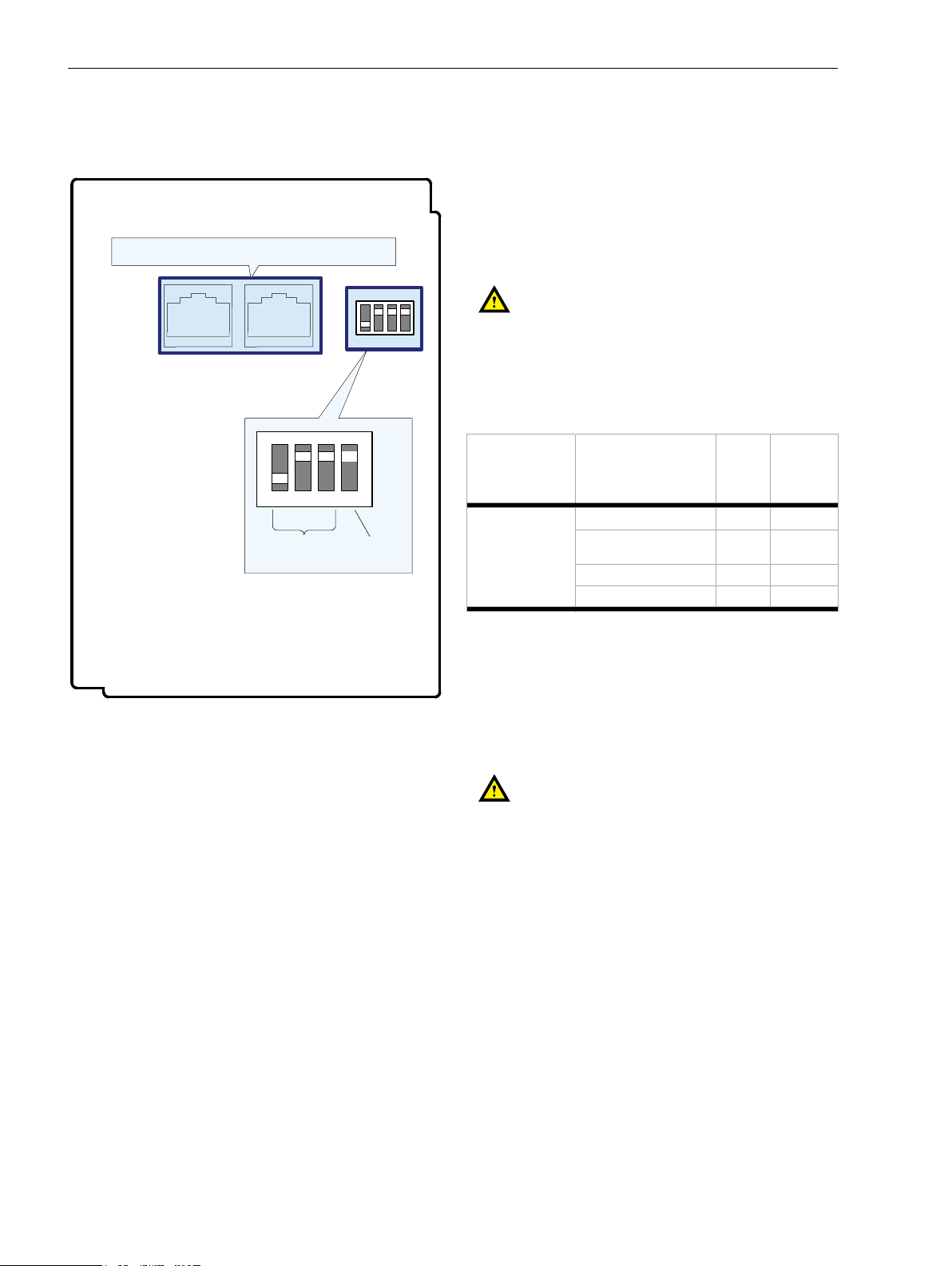
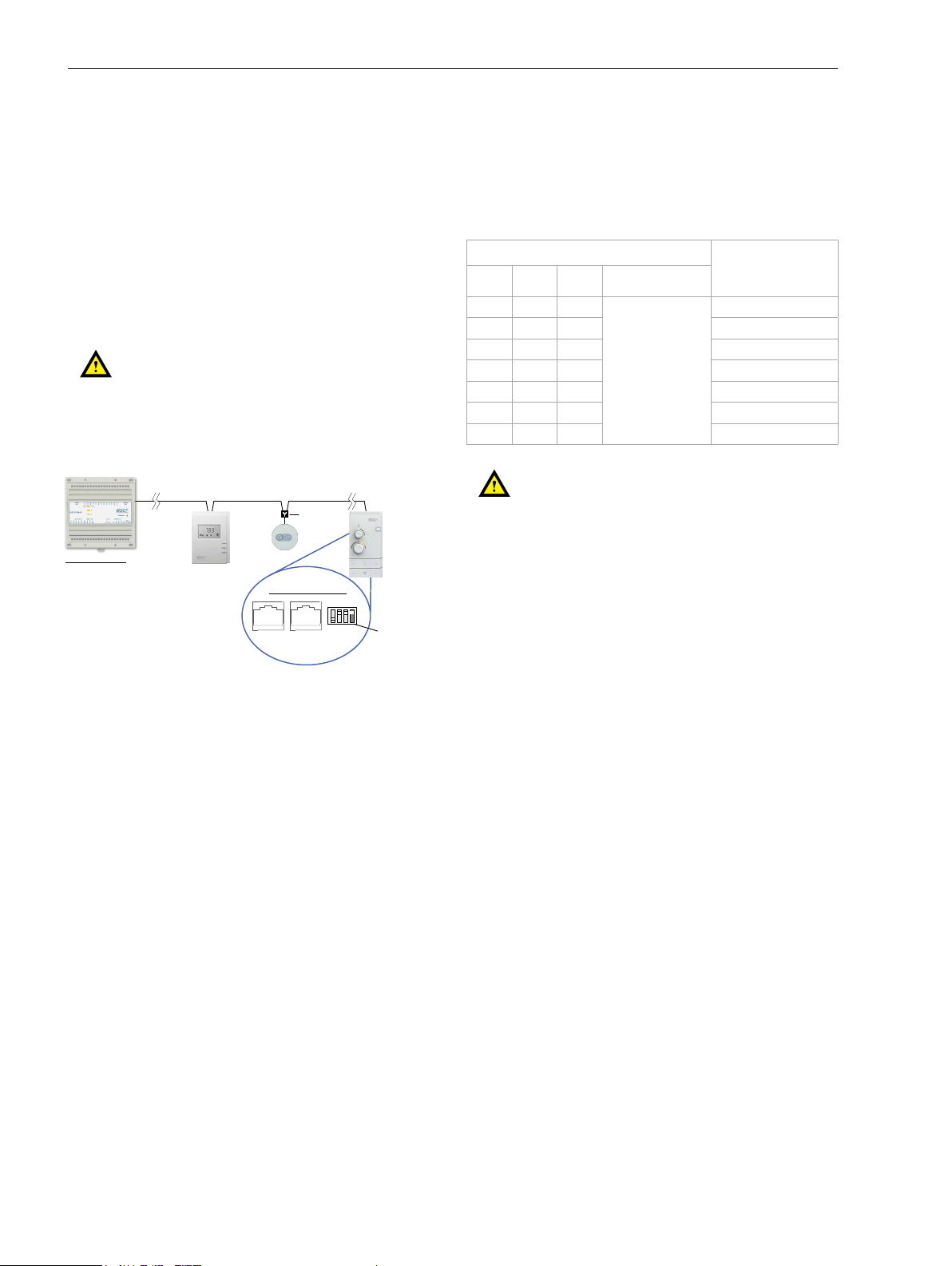
12. Set the Subnet ID and the EOL termination with the dipswitch as
explained in section Setting the Q.RCU-D-xx Sensor Subnet ID.
13. Connect the one or two RJ-45 cables into the sensor (reversable)
14. If using digital inputs, connect the digital wires to the digital
input cable as specied in section About an Q.RCU-D-xx Sensor
equipped with a digital input cable, and the digital input cable
connector into the sensor as shown on Figure 6: Connectors
and Dipswitch Locations.
15. Gently push excess wiring back into the wall.
16. Reattach the front plate and make sure it clips tightly into place.
17. Install the security screw.
18. Plug the Q.RCU-D-L Light/Blind add-on modules into the back
plate (if applicable).
19. Screw the Q.RCU-D-L Light/Blind add-on module(s) onto the
wall. Do not over tighten (if applicable).
20. Attach the Q.RCU-D-L Light/Blind add-on modules front plates
(if applicable).
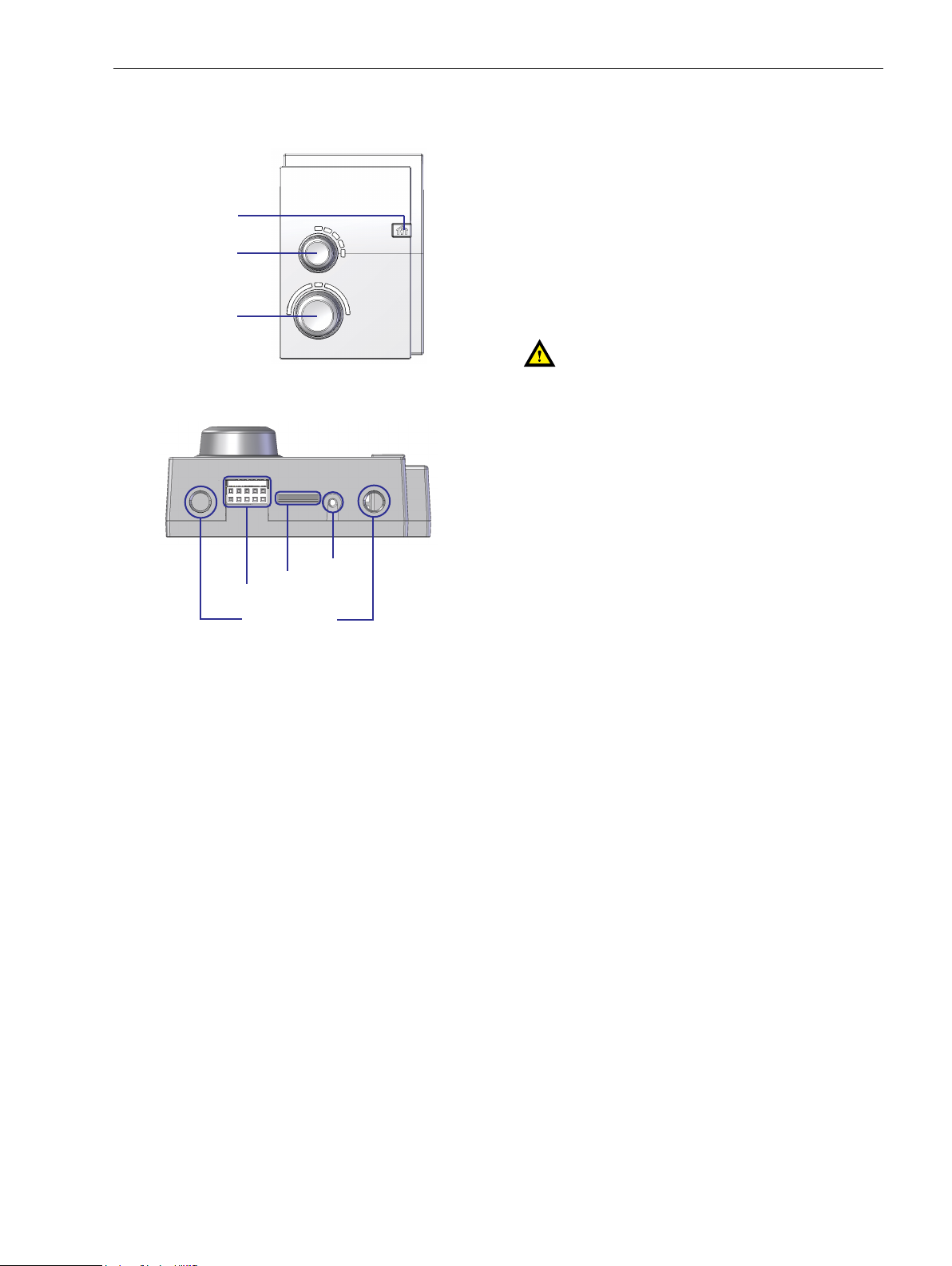
Device Components
Fan speed
selection knob
Temperature setpoint
offset knob
Occupancy
button
Q.RCU-D-xx Sensor - Front elements
Security screw
Locking tab
Q.RCU-D-x Light/Blind
add-on electrical connection
Q.RCU-D-x Light/Blind
add-on mechanical plug
Figure 5: Q.RCU-D-xx Sensor - Bottom elements
3
/8
www.sbc-support.com Installation Guide | 26-604_ENG01 02-2016
Saia-Burgess Controls AG
Q.RCU-D-xx Series