3
Introduction
The Sea-Bird Scientific SeapHOx™ combines a Satlantic SeaFET™ pH sensor with a Sea-Bird Electronics
SBE 37SMP-ODO MicroCAT CTD+DO sensor. The SeapHOx package provides integrated data collection of pH along
with temperature, salinity, and oxygen, and also allows for real-time temperature and salinity corrections of the
pH measurements. The SeapHOx is intended for moored applications to 50 m depth. The SeapHOx integration
approach was originally developed by Dr. Todd Martz of Scripps Institution of Oceanography.
The SeaFET controls the MicroCAT to collect CTD (conductivity, temperature, pressure), and dissolved oxygen (DO)
samples. Interface with the SeapHOx is through the SeaFET, using Satlantic’s SeaFETCom software package and
the SeaFET USB programming cable.
Integration with the MicroCAT is available in the following SeaFET operational modes:
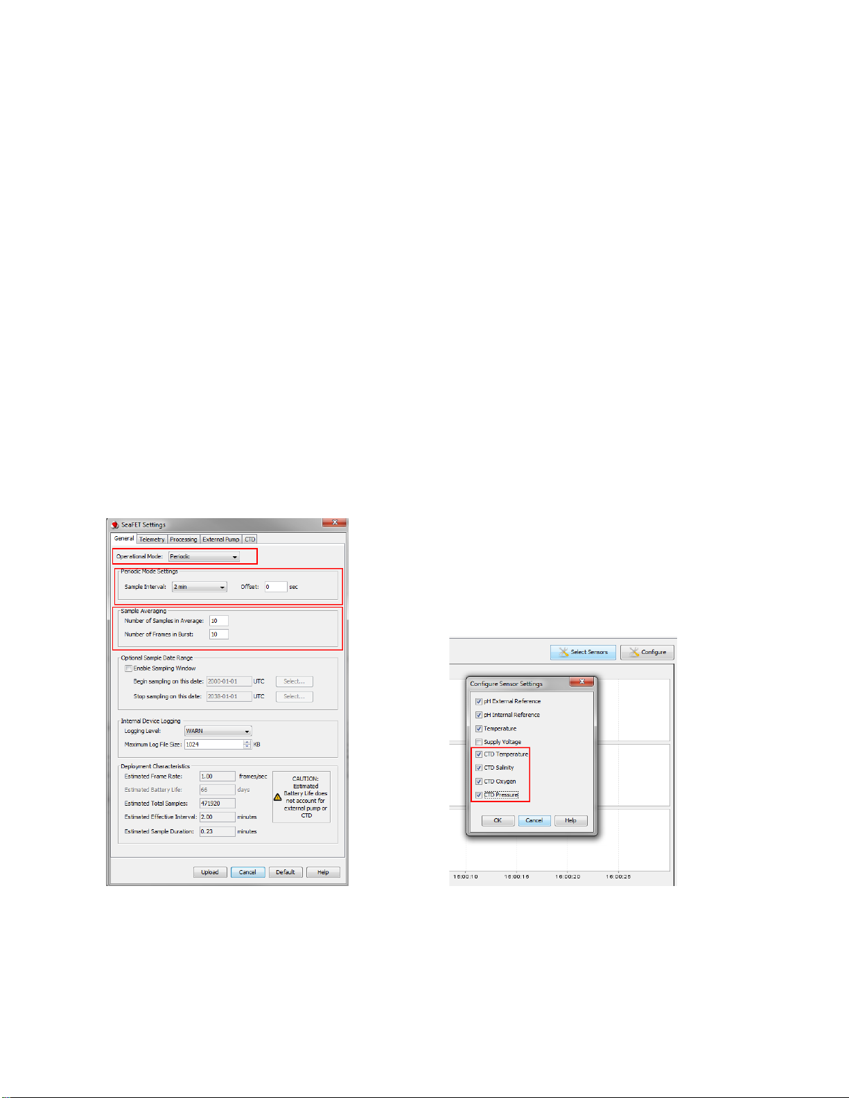
•SeaFET’s periodic mode - for stand-alone deployment
•SeaFET’s polled mode - for logger-controlled deployment
The SeaFET periodically polls for CTD data and uses itto calculate pH, applying real-time temperature and salinity
corrections to the pH data. The SeaFET stores the MicroCAT data (temperature, salinity, pressure, and oxygen)
along with the pH data. Because the MicroCAT runs its pump before taking a measurement, it takes approximately
40 seconds* after a sampling event starts before the MicroCAT can output data for the SeaFET to use in the pH
calculation. Therefore, SeaFET output frames will not appear at the telemetry port until 40+ seconds have elapsed.
Also note that power consumption in the SeaFET is increased due to the extended time the SeaFET needs to be
active for each measurement. See the Battery Endurance section in the SeaFET manual for an example of how
integration with the MicroCAT impacts power consumption.
* Note: With a typical oxygen sensor response time of OxTau20=5.5 seconds and pump time multiplier OxNTau=7,
the pump time is 38.5 seconds (OxNTau * OxTau20 = 7 * 5.5 = 38.5) before each measurement. See the MicroCAT
manual for details.
Unpacking SeapHOx
The SeapHOx ships from the factory with the mounting hardware installed. Also included in the shipment:
•Lithium cells - twelve 3.6-volt AA lithium cells to power the MicroCAT, in a heat-sealed plastic bag placed in
bubble wrap and a cardboard box.
Warning! Do not ship the instrument with the battery pack installed. See the MicroCAT manual for shipping
details.
•SeaFET USB programming cable for interfacing with the SeapHOx
•2.4 meter interface cable for testing MicroCAT
•Y-cable for connecting SeaFET to MicroCAT and to computer
•CD, which includes software and user manuals
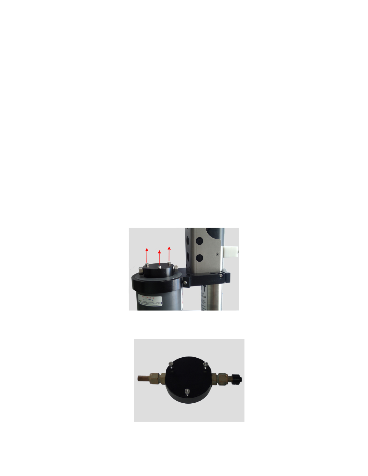
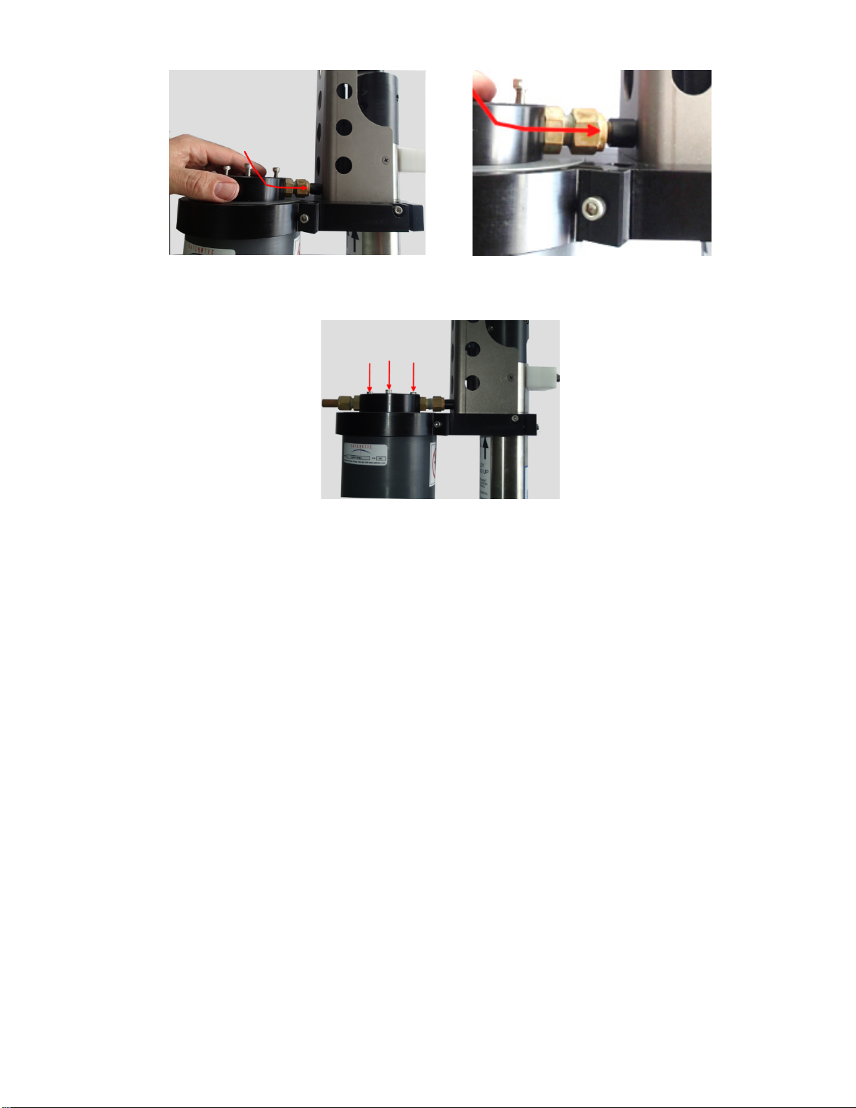
•SeaFET flow cell
•SeaFET flow cell fittings