manuals.online logo
Brands
  1. Home
  2. •
  3. Brands
  4. •
  5. SBG Systems
  6. •
  7. Accessories
  8. •
  9. SBG Systems EKINOX Series User manual

SBG Systems EKINOX Series User manual

EKINOX Series
Tactical Grade MEMS Inertial Sensors
Hardware Manual
Document EKINOXV3HM.1.
Revision 1. - Jun 14, 0
Covers Hardware Ekinox V3 and above
Support EMEA
[email protected]
+33 1 80 88 43 70
Americas
[email protected]
+1 (657) 549-5807
EKINOX Series – Hardware Manual EKINOXV3HM.1.
Revision history
Rev. Date Author Information
1.3 Jun 14, 0 Alexis Guinamard [EK3HM-5] Ekinox hardware manual wrong connector on split cable picture
[EK3HM-4] Accessories Update
[EK3HM-6] Fixed Ship Motion HP latency to 150s
[EK3HM-10] Specify RTK performance according to baseline
[EK3HM-1 ] Update orientation specifications after algorithms update
[EK3HM-13] Transferred antennas section to support center
[EK3HM- ] Wrong description on automotive connection example
1.1 Sep 5, 019 Alexis Guinamard [EK3HM-1] Updated Ordering codes
1 Mar 1 , 019 Alexis Guinamard First public version
© 007 – 0 SBG Systems SAS. All rights reserved. Information in this document is subject to change
without notice. Copy or redistribution of this document is forbidden without express authorization of
SBGSystems.
/46
EKINOX Series – Hardware Manual EKINOXV3HM.1.
Index
Terminology............................................................................................................................................................ 6
1. Introduction........................................................................................................................................................ 7
1.1. Ekinox Overview......................................................................................................................................... 8
. Performance specification................................................................................................................................ 9
.1. Inertial measurement unit........................................................................................................................ 9
.1.1. Accelerometers......................................................................................................................................................................... 9
.1. . Gyroscopes............................................................................................................................................................................... 9
. . Aiding sensors......................................................................................................................................... 10
. .1. Ekinox D internal GNSS receiver............................................................................................................................................ 10
. . . External aiding sensors......................................................................................................................................................... 10
.3. Orientation and Navigation Performance................................................................................................ 11
.3.1. Common specifications........................................................................................................................................................... 11
.3. . Land applications................................................................................................................................................................... 11
.3.3. Marine & Subsea applications............................................................................................................................................... 1
.3.3.1. Heave performance....................................................................................................................................................... 1
.3.4. Airborne applications............................................................................................................................................................ 1
.3.5. Real time Performance monitoring...................................................................................................................................... 1
3. Mechanical specifications................................................................................................................................ 13
3.1. Overview................................................................................................................................................... 13
3.1.1. Main Specifications................................................................................................................................................................. 13
3.1. . Device mechanical alignment................................................................................................................................................ 14
3.1.3. Origin of measurements........................................................................................................................................................ 14
3.1.4. Device label............................................................................................................................................................................. 14
3. . Ekinox A and E mechanical outline......................................................................................................... 15
3. .1. Top view.................................................................................................................................................................................. 15
3. . . Right view.............................................................................................................................................................................. 15
3. .3. Front view.............................................................................................................................................................................. 16
3. .4. Bottom view.......................................................................................................................................................................... 16
3.3. Ekinox D mechanical outline.................................................................................................................... 17
3.3.1. Top view.................................................................................................................................................................................. 17
3.3. . Right view.............................................................................................................................................................................. 17
3.3.3. Front view.............................................................................................................................................................................. 18
3.3.4. Bottom view.......................................................................................................................................................................... 18
4. Electrical specifications................................................................................................................................... 19
4.1. Overview................................................................................................................................................... 19
4.1.1. Ekinox-A and E with external aiding only.............................................................................................................................. 19
4.1. . Ekinox D with dual antenna GNSS........................................................................................................................................ 19
4. . Power supply connector......................................................................................................................... 0
4. .1. Connector specifications....................................................................................................................................................... 0
3/46
EKINOX Series – Hardware Manual EKINOXV3HM.1.
4. . . Connector pin out................................................................................................................................................................. 0
4. .3. Electrical specifications......................................................................................................................................................... 1
4.3. Main connector........................................................................................................................................ 1
4.3.1. Connector specifications........................................................................................................................................................ 1
4.3. . Connector pin out.................................................................................................................................................................
4.3.3. Electrical specifications........................................................................................................................................................ 3
4.4. Auxiliary connector................................................................................................................................. 4
4.4.1. Connector specifications....................................................................................................................................................... 4
4.4. . Connector pin out................................................................................................................................................................. 4
4.4.3. Electrical specifications........................................................................................................................................................ 5
4.5. GPS antenna connectors........................................................................................................................ 6
4.5.1. Electrical specifications......................................................................................................................................................... 6
4.5. . GPS antenna advice.............................................................................................................................................................. 6
4.6. Typical wiring........................................................................................................................................... 7
4.6.1. Power supply connection....................................................................................................................................................... 7
4.6. . Main interface connection on RS- 3 .................................................................................................................................. 7
4.6.3. Main interface connection on RS-4 ................................................................................................................................. 8
4.6.4. CAN Bus typical wiring......................................................................................................................................................... 8
4.6.5. GNSS connection in RS- 3 mode....................................................................................................................................... 9
4.6.6. Third party aiding equipment connected in RS-4 ........................................................................................................... 9
4.6.7. Triggering external devices with the sync Out..................................................................................................................... 9
4.7. Typical connection topologies................................................................................................................. 30
4.7.1. Ekinox-D in advanced automotive application..................................................................................................................... 30
4.7. . Ekinox-E in marine application.............................................................................................................................................. 31
5. Interfaces specifications................................................................................................................................. 3
5.1. Overview................................................................................................................................................... 3
5. . Ethernet specifications........................................................................................................................... 3
5. .1. Accessing the Ekinox web page............................................................................................................................................ 3
5.3. Serial interfaces...................................................................................................................................... 33
5.4. Supported protocols................................................................................................................................ 33
5.5. Synchronization Inputs and outputs...................................................................................................... 33
5.5.1. SYNC In A, B, C, D and E........................................................................................................................................................ 33
5.5. . SYNC OUT A, B...................................................................................................................................................................... 34
5.6. Connections Mapping............................................................................................................................. 34
5.6.1. Ekinox-A................................................................................................................................................................................. 34
5.6. . Ekinox-E................................................................................................................................................................................ 34
5.6.3. Ekinox-D................................................................................................................................................................................ 34
5.7. Internal Datalogger.................................................................................................................................. 35
5.8. CAN .0 A/B interface............................................................................................................................ 35
6. Important notices........................................................................................................................................... 36
6.1. Maintenance............................................................................................................................................ 36
6. . Absolute maximum ratings.................................................................................................................... 36
6.3. Support.................................................................................................................................................... 37
4/46
EKINOX Series – Hardware Manual EKINOXV3HM.1.
6.4. Warranty, liability and return procedure................................................................................................. 37
7. Appendix A: Ordering codes and Accessories................................................................................................. 38
7.1. Ekinox variants......................................................................................................................................... 38
7. . Transport Cases....................................................................................................................................... 38
7. .1. CASE-EKI-01........................................................................................................................................................................... 38
7. . . CASE-AEK-01......................................................................................................................................................................... 38
7.3. Associated Software............................................................................................................................... 39
7.3.1. Inertial SDK............................................................................................................................................................................. 39
7.3. . SW-QINERTIA-PRO (GNSS/INS Post Processing Software)................................................................................................39
7.4. Cables....................................................................................................................................................... 40
7.4.1. CA-AEK-PWR-PSU-1.5M........................................................................................................................................................ 40
7.4. . CA-AEK-PWR-3M.................................................................................................................................................................. 40
7.4.3. CA-AEK-MAIN-ETH- .5M...................................................................................................................................................... 40
7.4.4. CA-AEK-MAIN-RS 3 -3M...................................................................................................................................................... 41
7.4.5. CA-AEK-MAIN-RS4 -3M..................................................................................................................................................... 4
7.4.6. CA-AEK-AUX-3M.................................................................................................................................................................... 43
7.4.7. CA-AEK-SPLIT-MAIN-0.5M.................................................................................................................................................... 44
7.4.8. CA-AEK-SPLIT-MAIN -0.5M................................................................................................................................................. 45
7.4.9. CA-AEK-SPLIT-AUX-0.5M...................................................................................................................................................... 46
5/46
EKINOX Series – Hardware Manual EKINOXV3HM.1.
Terminology
ADC: Analog to Digital Converter
AHRS: Attitude and Heading Reference System
CAN (Bus): Controller Area Network
DHCP: Dynamic Host Configuration Protocol
DVL: Doppler Velocity Log
EKF: Extended Kalman Filter
EEPROM: Electrically-Erasable Programmable Read-Only Memory
FIR: Finite Impulse Response (filter)
FTP: File Transfer Protocol
FS: Full Scale
FOG: Fiber Optic Gyroscope
GNSS: Global Navigation Satellite System
GPS: Global Positioning System
IIR: Infinite Impulse Response (filter)
IMU: Inertial Measurement Unit
INS: Inertial Navigation System
IP: Internet Protocol
LBL: Long Baseline
MAC (address): Media Access Control
MEMS: Micro Electro-Mechanical Systems
NED: North East Down (coordinate frame)
NA: Not applicable
NMEA (NMEA 0183): National Marine Electronics Association (standardized communication protocol)
PPS: Pulse Per Second (signal)
RAM: Random Access Memory
RMA: Return Merchandise Authorization
RMS: Root Mean Square
RTCM: Radio Technical Commission for Maritime Services (Protocol)
RTK: Real Time Kinematics
SI: International System of Units
TBD: To Be Defined
TCP: Transmission Control Protocol
UDP: User Datagram Protocol
UTC: Coordinated Universal Time
USBL: Ultra Short Base Line
VRE: Vibration Rectification Error
WGS84: World Geodetic System 1984
WMM: World Magnetic Model
6/46
EKINOX Series – Hardware Manual EKINOXV3HM.1.
1. Introduction
Ekinox series is a line of very high performance, MEMS based
Inertial Systems which achieve exceptional orientation and
navigation performance in a compact and affordable package. It
includes a cutting edge Inertial Measurement Unit (IMU) and runs
an on-board enhanced Extended Kalman Filter (EKF). The Ekinox
line is divided in a comprehensive set of sensors:
●The Ekinox-A version is a Motion Reference Unit (MRU) or
Attitude and Heading Reference System (AHRS), providing
accurate roll and pitch in dynamic conditions as well as heave,
surge and sway outputs. The Ekinox A can be connected to an
external GNSS receiver to benefit from absolute heading
measurement and improved roll and pitch performance.
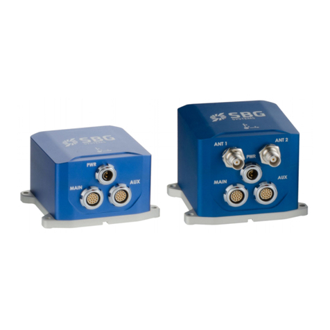
●The Ekinox-E and D models are Inertial Navigation Systems
(INS), providing both orientation and navigation data even during GNSS outages. Various aiding
sensors can be used to provide accurate navigation data in all conditions, but also to improve
orientation accuracy:
●The Ekinox-E model can be connected to external aiding equipment such as two GNSS receivers, 1x
DVL or odometer. SBGSystems has developed dedicated “split” cables to simplify the integration
with external equipment.
●The Ekinox-D embeds a dual antenna, survey grade L1/L GNSS receiver that supports GPS,
GLONASS GALILEO and BEIDOU constellations. If features RTK positioning as well as RAW data
support in standard for centimeter precision in real time or post-processing. The dual antenna
enables precise heading in low dynamic applications.
To achieve the best performance in every project, specific error models have been implemented to meet
applications requirements and to adapt the Ekinox to your vehicle. Sensor configuration is made easy
through the modern embedded web interface.
The windows based sbgCenter application also provides a very powerful and easy to use tool to monitor,
analyze, record, playback and export all measurements, status and information of your Ekinox.
Finally, the 8 Go embedded data-logger enables seamless post processing work-flow with Qinertia post-
processing software for the most demanding applications.
The third generation of Ekinox remains fully compatible with previous Ekinox series.
7/46
Figure 1.1: The Ekinox-E model
EKINOX Series – Hardware Manual EKINOXV3HM.1.
1.1. Ekinox Overview
The following diagram shows the basic organization of an Ekinox-A, E or D. On the Ekinox-A and E versions,
this block diagram is slightly simplified as there is no embedded GNSS.
8/46
Figure 1. : Ekinox simplified block diagram
IMU DATA FUSION
Coning & Sculling
integrals @ 1 kHz
3 Axis
Gyroscopes
3 Axis
Accelerometers
EKF and output
@ 00 Hz
POWER
ETHERNET
FTP
CAN
SERIAL
Data loggerGNSS
A B C D
Aiding Equipments
» Navigation: x RTK GPS/GNSS
» Heading: Dual Antenna GPS/GNSS
» Velocity: Odometer, DVL
EKINOX Series – Hardware Manual EKINOXV3HM.1.
. Performance specification
.1. Inertial measurement unit
The IMU is the core component of an inertial navigation system. Leveraging on MEMS technology and an
innovative proprietary integration, the Ekinox IMU delivers an exceptional performance while maintaining a
reasonable cost.
.1.1. Accelerometers
The Ekinox IMU contains a set of 3 MEMS capacitive accelerometers. Coupled with advanced filtering
techniques and sculling integrals, these accelerometers will provide quartz performance level. Thanks to a
very low VRE, the performance is maintained in highly vibrating environments.
A A3 Remarks
Full scale (
g
)± 8 ± 14
Velocity Random Walk (µ
g
/√hz) 7 40 Allan variance – @ 5°C
In run bias instability (µ
g
)10 Allan variance – @ 5°C
Vibration Rectification Error (µ
g
/
g
²) < 00 <50 VRE – 0 Hz – kHz
Bandwidth (Hz) 433 433 Attenuation of 3 dB
Orthogonality (°) < 0.0 < 0.0 Over temperature range
.1. . Gyroscopes
The set of 3 high end tactical grade MEMS gyroscopes is sampled at .3 kHz. A specific integration design
as well advanced signal processing (FIR filters, coning integrals) ensure best performance in vibrating
environments.
G4 Remarks
Full scale (°/s) ± 300
In run bias instability (°/hr) 0.5 Allan variance – @ 5°C
Angular Random Walk (°/√hr) 0.14 Allan variance – @ 5°C
Bandwidth (Hz) 60 Attenuation of 3 dB
Orthogonality (°) < 0.0 Over temperature range
9/46
EKINOX Series – Hardware Manual EKINOXV3HM.1.
. . Aiding sensors
Many different aiding sensors can be used to aid the Ekinox INS.
. .1. Ekinox D internal GNSS receiver
The EKINOX-D embeds a survey grade GNSS receiver (L1/L GPS, GLONASS, GALILEO, BEIDOU), capable of
SBAS, DGPS, and RTK positioning. With a refresh rate of 5Hz, this receiver provides best accuracy and
reliability in harsh GNSS environments. The standard RAW data output enables highest performance in
post-processing applications.
Specification Remark
Channels 448
Signal tracking GPS: L1, L , L C
GLONASS: L1, L
GALILEO: E1 B/C, E5b
Beidou B1, B ,
SBAS, QZSS
All constellations & signals enabled by
default
Horizontal position accuracy Single point L1/L 1. m RTK precision available in option
SBAS / DGPS 0.6 m / 0.4 m
RTK 1 cm + 1ppm
Velocity accuracy 0.03 m/s RMS
True Heading Accuracy 0.15°
0.1°
1m baseline
m baseline
Velocity limit 515 m/s Due to export licenses
Time to First Fix Cold start < 45 s
Hot start < 0s
Signal reacquisition 1s
Output frequency 5 Hz
Diff. Corrections RTCM V .x, V3.x
CMR V .0, CMR+
Sent via serial PORT C
Options RTK
Note: All these specifications reflect the intrinsic GNSS receiver accuracy. Please refers to section .3
Orientation and Navigation Performance for complete Ekinox accuracy specifications.
. . . External aiding sensors
The Ekinox-A accepts a single external GNSS receiver connection to improve orientation performance. It can
be a dual antenna receiver for precise heading output.
The Ekinox-E and D models accept up to two external GNSS receivers to provide navigation data and
improve orientation performance. In addition, a DVL or an odometer can be connected on Ekinox-E/D as
velocity aiding inputs.
10/46
EKINOX Series – Hardware Manual EKINOXV3HM.1.
.3. Orientation and Navigation Performance
All specifications are rated to 1σ, over -40°C to +75°C unless otherwise stated.
These specifications have been obtained by field tests, using typical mission scenarios and comparison to
reference units using post-processing. Outage performance validated by simulation of repeated, pure GNSS
outages, separated by at least 00s of optimal GNSS condition, compared to a reference RTK trajectory.
Performance parameters may be affected in multi-path and poor GNSS reception environments such as
Urban canyons.
For each application, we present the specified accuracy for the following positioning modes:
●SP: Single Point mode and is the default L1 GPS fix quality
●RTK: Real Time Kinematics with a typical 1 cm accuracy position
●PP: Post Processed data using Qinertia
.3.1. Common specifications
Performance Remarks
Measurement range 360° in all axes, no mounting limitation Solid state sensors
Orientation noise < 0.0 ° RMS Static
.3. . Land applications
All specifications are valid with DMI (odometer) aiding for typical land mapping trajectories.
Outage
Duration Positioning Mode Position Accuracy Velocity Accuracy Attitude Accuracy
Horizontal Vertical Horizontal Vertical Roll/pitch Heading
0 s
SP 1. 0 m 1. m 0.05 m/s 0.05 m/s 0.0 ° 0.05°
RTK 0.01 m + 1ppm 0.0 m + 1ppm 0.0 m/s 0.0 m/s 0.015° 0.04°
PP 0.01 m + 1ppm 0.0 m + 1ppm 0.01 m/s 0.01 m/s 0.01° 0.03°
10 s
SP 1.5 m 1.4 m 0.05 m/s 0.05 m/s 0.03° 0.06°
RTK 0.15 m 0.1 m 0.03 m/s 0.03 m/s 0.0 ° 0.05°
PP 0.03 m 0.03 m 0.015 m/s 0.01 m/s 0.015° 0.03°
60 s / 1km
SP 4 m ,5 m 0.1 m/s 0.1 m/s 0.08° 0.15°
RTK 3 m 0.75 m 0.1 m/s 0.1 m/s 0.08° 0.1 °
PP 0.4 m 0.1 m 0.03 m/s 0.0 m/s 0.03° 0.05°
11/46
EKINOX Series – Hardware Manual EKINOXV3HM.1.
.3.3. Marine & Subsea applications
All specifications are valid with dual antenna aiding for typical marine survey trajectories.
Outage
Duration Positioning Mode Position Accuracy Velocity Accuracy Attitude Accuracy
Horizontal Vertical Horizontal Vertical Roll / Pitch Heading
0 s
SP 1. 0 m .0m 0.05 m/s 0.05 m/s 0.0 ° 0.03° (baseline > m)
0.0 ° (baseline > 4m)
RTK 0.01 m + 1ppm 0.0 m + 1ppm 0.0 m/s 0.0 m/s 0.015°
PP 0.01 m + 1ppm 0.0 m + 1ppm 0.01 m/s 0.01 m/s 0.01° 0.0 °
10 s
SP . m .5m 0.1 m/s 0.05 m/s 0.05° 0.06° (baseline > m)
0.05° (baseline > 4m)
RTK 0.3 m 0.1m 0.05m/s 0.03 m/s 0.05°
PP 0.05 m 0.03 m 0.0 m/s 0.01 m/s 0.0 ° 0.03°
30 s
SP 4.0m .5 m 0.3m/s 0.15 m/s 0.1° 0.15° (baseline > m)
0.13° (baseline > 4m)
RTK 3.0 m 0.75 m 0. 5 m/s 0.1 m/s 0.1°
PP 1.0 m 0.3 m 0.05 m/s 0.03 m/s 0.04° 0.05°
.3.3.1. Heave performance
Real Time Heave Delayed Heave (ShipMotionHP) Remark
Range 50 meters 50 meters Automatic adjustment to every sea
conditions
Period 0 to 0 s 0 to 40 s
Accuracy 5 cm or 5% cm or .5 % Whichever is greater; Velocity aided heave
Mode Real time, auto tuning Fixed 150s delay On board computation
.3.4. Airborne applications
Specifications evaluated with a dual antenna heading source.
Positioning Mode Position Accuracy Velocity Accuracy Attitude Accuracy
Horizontal Vertical Horizontal Vertical Roll Heading
SP 1. 0 m .0m 0.05 m/s 0.05 m/s 0.0 ° 0.03° (baseline > m)
0.0 ° (baseline > 4m)
RTK 0.01m + 1ppm 0.0 m + 1ppm 0.0 m/s 0.0 m/s 0.015°
PP 0.01 m + 1ppm 0.0 m + 1ppm 0.01 m/s 0.01 m/s 0.01° 0.0 °
.3.5. Real time Performance monitoring
The Extended Kalman filter provides feedback about its performance. The following validity levels
thresholds are defined for the Ekinox series
Threshold Comments
Attitude Valid 0.3° / 0.07° AHRS / Normal INS mode
Heading Valid 0.5° / 0. ° AHRS / Normal INS mode
Velocity Valid 0. m/s Total velocity error (3D)
Position Valid 1m Total position error (3D)
Note: The thresholds are less accurate in AHRS mode, when there is no GNSS aiding available. Full
performance can be reached with GNSS aiding.
1 /46
EKINOX Series – Hardware Manual EKINOXV3HM.1.
3. Mechanical specifications
3.1. Overview
The Ekinox enclosure is composed of two anodized aluminum parts, one for the cover and one for the base
plate. The device uses high quality alloys and connectors to offer a full IP-68 enclosure and a good
resistance to harsh environments.
The cover part is made of 6061 aluminum alloy for its resistance to both seawater and industrial chemical
environments. In addition, this material offers a nice visual aspect.
The base plate is made of 7075 aluminum alloy to ensure best durability and accuracy. Indeed, this alloy
offers an incredible mechanical strength to guarantee the base plate integrity and accuracy during device
installation.
The cover and base plates are sealed together by four M3 stainless steel A4 screws (3016L). The Ekinox
should be installed to the host interface using four M4 stainless steel A4 screws.
The Ekinox connectors are high quality Fischer connectors that offers IP-68 protection even unconnected.
The Ekinox-D also include TNC connectors to plug the GPS antennas.
Warning: The Ekinox surface model is not designed for prolonged operation in salt water
environments. Check section Maintenance for more details about operation in sea water
environments.
3.1.1. Main Specifications
The table below summarizes all mechanical and environmental specifications.
Mechanical Specifications
A / E D
Height 5.8 cm ( , 8”) 7.5 cm ( .9”)
Width 10 cm (3,94”) 10 cm (3,94”)
Depth 8.6 cm (3,39”) 8.6 cm (3,39”)
Weight 435 g (1.0 lb) 610 g (1.3 lb)
Shocks 500 g for 0.3 ms
Operating Vibrations 3g RMS – 0Hz to kHz as per MIL-STD-810G (A range options)
8g RMS – 0Hz to kHz as per MIL-STD-810G (A3 range options)
Environmental Specifications
Enclosure Anodized Aluminum
IP rating IP-68 ( 4 hours at meters)
Operating temperature -40 to 75°C (-40 to 167°F)
Storage -40 to 85°C (-40 to 185°F)
Humidity Sealed, no limit
MTBF (computed) 50.000 hours
Calibration interval None required, maintenance free
13/46
EKINOX Series – Hardware Manual EKINOXV3HM.1.
3.1. . Device mechanical alignment
For best measurement accuracy, a good mechanical alignment is required. During manufacturing, the
Ekinox measurement frame has been carefully aligned to 0.0 ° with the base plate for roll, pitch and yaw
angles.
To ease the yaw alignment (X axis), the base plate features two alignment holes Ø 4 mm H8 that
guarantees with two taper pins Ø 4 mm h7 a yaw alignment better than ±0.04°.
Note: The base plate is the same for the Ekinox A, E and D models.
3.1.3. Origin of measurements
The Ekinox offers the possibility to output data at different measurement points.
The default center of measurement is located on top of Ekinox enclosure, on the coordinate frame center
drawing. It is represented on the mechanical outlines by the symbol. This point is defined to simplify
installation.
Alternatively, user can select between two other center of measurement points:
●Alignment hole (aligned to the bottom of the base plate)
●Bare IMU center of measurement, represented by the symbol.
3.1.4. Device label
SBG Systems manufacturing process is based on EN-9100 system with individual and full traceability of
every component and operation. Each Ekinox is identified by a unique serial number that can be used to
trace all operations during the product lifetime such as manufacturing, calibration, tests and repairs.
In addition to a unique serial number, a product code is used to define exactly the device type and options.
You can find on the back side of the Ekinox a laser printed label that hold all these identification
information. This label also includes a data-matrix code that encodes the device unique serial number.
In addition, the Ekinox packaging includes a second label that provides other useful information such as
installed firmware version or GNSS options in the case of an Ekinox-D.
14/46
Figure 3.1: Ekinox device label sample Figure 3. : Ekinox packaging label sample
EKINOX Series – Hardware Manual EKINOXV3HM.1.
3. . Ekinox A and E mechanical outline
All dimensions are in mm.
3. .1. Top view
3. . . Right view
15/46
100 ±0,30
86 ±0,30 3,75
4 HOLES 4,50
82
17
26,10
EKINOX Series – Hardware Manual EKINOXV3HM.1.
3. .3. Front view
3. .4. Bottom view
16/46
0,50
7
58
12 12
25
44
38 ±0,01
75
64 ±0,10
91 ±0,10
4 H7 2,5
6
4 H7 2,5
28,80
27,70
EKINOX Series – Hardware Manual EKINOXV3HM.1.
3.3. Ekinox D mechanical outline
All dimensions are in mm.
3.3.1. Top view
3.3. . Right view
17/46
100 ±0,30
86 ±0,30
3,75
4 HOLES 4,50
14,40
82
17
26,10
EKINOX Series – Hardware Manual EKINOXV3HM.1.
3.3.3. Front view
3.3.4. Bottom view
18/46
0,50
7
58
75
14,50 14,50
25
12 12
43
38 ±0,01
75
64 ±0,10
91 ±0,10
4 H7 2,5
6
4 H7 2,5
28,80
27,70
EKINOX Series – Hardware Manual EKINOXV3HM.1.
4. Electrical specifications
4.1. Overview
The Ekinox connectors are all placed on the front panel. The connectors are referenced and identified by
laser marking on the enclosure. Each connector is different and fool proofed using a specific keying to avoid
any misconnection.
SBG Systems has selected high quality connectors designed for harsh environments. They offer an IP-68
protection when the plug is properly mounted.
4.1.1. Ekinox-A and E with external aiding only
Ekinox-A and E share the same form factor.
4.1. . Ekinox D with dual antenna GNSS
19/46
Figure 4.1: Ekinox AHRS or INS with external aiding
Power supply
External aiding
connector
Main connector
Figure 4. : Ekinox INS with integrated GNSS receiver
Secondary
GPS Antenna
External aiding
connector
Power supply
Primary
GPS Antenna
Main connector
EKINOX Series – Hardware Manual EKINOXV3HM.1.
4. . Power supply connector
The Ekinox can be powered by a DC voltage from 9 to 36 Volts. For best robustness and to reduce power
consumption, the internal power module is a high efficiency isolated DC/DC converter.
Apply a constant power supply to VIN+ and VIN- pins. The shield is directly connected to the device
mechanical enclosure. It should not be used as the ground return signal.
4. .1. Connector specifications
The power supply uses a ways male AluLite Fischer connector which is compatible with the Fischer Core
Series. The exact receptacle reference is: AL1731-DBPU-103-Z051PB11-1 G13
This size 103 connector mates with the following plugs references in AluLite or Core Series. Alternative
plugs can be found if required (eg short plug). Don't forget that these two references don't include the cable
clamp sets.
●AL1731-S-103-Z051SR11-11 (AluLite version)
●S-103-Z051-130 (Core Series version)
Note: Although Fischer connectors are IP68 and specified to operate from -40°C to +75°C, the plug
should be connected at temperatures above - 0°C and in a dry environment.
Warning: The power receptacle uses male connectors for obvious security reasons. Please make sure
that you order the correct plug reference.
4. . . Connector pin out
Pin # Name Description
Shield Shield Connected to mechanical ground
1VIN+ Connected to the power supply
VIN- Connected to the electrical ground
0/46
Figure 4.3: Power receptacle front view
Figure 4.4: Power plug top view

This manual suits for next models

3

Other SBG Systems Accessories manuals

SBG Systems Apogee Subsea Series User manual

SBG Systems

SBG Systems Apogee Subsea Series User manual

SBG Systems Apogee Surface Series User manual

SBG Systems

SBG Systems Apogee Surface Series User manual

SBG Systems Apogee Surface Series User manual

SBG Systems

SBG Systems Apogee Surface Series User manual

SBG Systems ELLIPSE 2 AHRS User manual

SBG Systems

SBG Systems ELLIPSE 2 AHRS User manual

SBG Systems Apogee Surface Series User manual

SBG Systems

SBG Systems Apogee Surface Series User manual

SBG Systems EKINOX 2 Series User manual

SBG Systems

SBG Systems EKINOX 2 Series User manual

SBG Systems IG-500A User manual

SBG Systems

SBG Systems IG-500A User manual

Popular Accessories manuals by other brands

Milltronics ILE-61 instruction manual

Milltronics

Milltronics ILE-61 instruction manual

ANSMANN POWERBANK 7.0 manual

ANSMANN

ANSMANN POWERBANK 7.0 manual

netvox R718N3 user manual

netvox

netvox R718N3 user manual

Dwyer Instruments ULS Series manual

Dwyer Instruments

Dwyer Instruments ULS Series manual

SPIETH Gymnastics Moscow Assembly and user's manual

SPIETH Gymnastics

SPIETH Gymnastics Moscow Assembly and user's manual

GRASS VALLEY 8949SVM-UMD datasheet

GRASS VALLEY

GRASS VALLEY 8949SVM-UMD datasheet

Orno OR-CR-218 quick guide

Orno

Orno OR-CR-218 quick guide

HOLZMANN MASCHINEN HMS 700 user manual

HOLZMANN MASCHINEN

HOLZMANN MASCHINEN HMS 700 user manual

PCB Piezotronics IMI SENSORS 641B62 Installation and operating manual

PCB Piezotronics

PCB Piezotronics IMI SENSORS 641B62 Installation and operating manual

Byron SX-202 quick start guide

Byron

Byron SX-202 quick start guide

PCB Piezotronics 356A25 Installation and operating manual

PCB Piezotronics

PCB Piezotronics 356A25 Installation and operating manual

Delta Electronics Delphi 6A Series datasheet

Delta Electronics

Delta Electronics Delphi 6A Series datasheet

UFESA FLEXY-HEAT BM instruction manual

UFESA

UFESA FLEXY-HEAT BM instruction manual

Bosch BME680 quick start guide

Bosch

Bosch BME680 quick start guide

Ursalink EM500 Series Configuration guide

Ursalink

Ursalink EM500 Series Configuration guide

Baumer 18N6903/S14 manual

Baumer

Baumer 18N6903/S14 manual

GSi VersaLoop owner's manual

GSi

GSi VersaLoop owner's manual

BT Starter Kit 2 user guide

BT

BT Starter Kit 2 user guide

manuals.online logo
manuals.online logoBrands
  • About & Mission
  • Contact us
  • Privacy Policy
  • Terms and Conditions

Copyright 2025 Manuals.Online. All Rights Reserved.