2
1. PRODUCT SPECIFICATION
1.1 Technical specifications :
GAS : G20 (Natural gas) - Category : I2Esi
MODEL
SX
SX
SX
SX
SX
SX
2SX
SX
2SX
SX
2SX
2SX
2SX
Weight (kg) 2.5 2.9 3.1 3.4 4.1 5.0 5.0 5.5 5.5 6.7 6.7 9.4 12.2
Net calorific value
Qn (kW) Hi 2.50 3.30 3.80 5.10 6.75 7.60 7.60 10.20 10.20 13.50 13.50 20.25 27.00
GAS
Inlet pressure 20 mbar
Injection pressure (mbar) 13.0 11.0 12.0 15.0 16.7 12.0 12.0 15.0 15.0 16.7 16.7 (See B)
16.7
Gas consumption (m3/h) 0.265 0.350 0.400 0.540 0.715 0.805 0.805 1.080 1.080 1.430 1.430 2.145 2.860
Ø prim. Inject. (1/100 mm) 170 180 195 240 320 260 2x195 380 2x240 - 2x320 (See A)
-
Ø sec. Inject. (1/100 mm) 135 165 170 180 195 2x170 2x170 2x180 2x180 2x195 2x195 (See A)
4x195
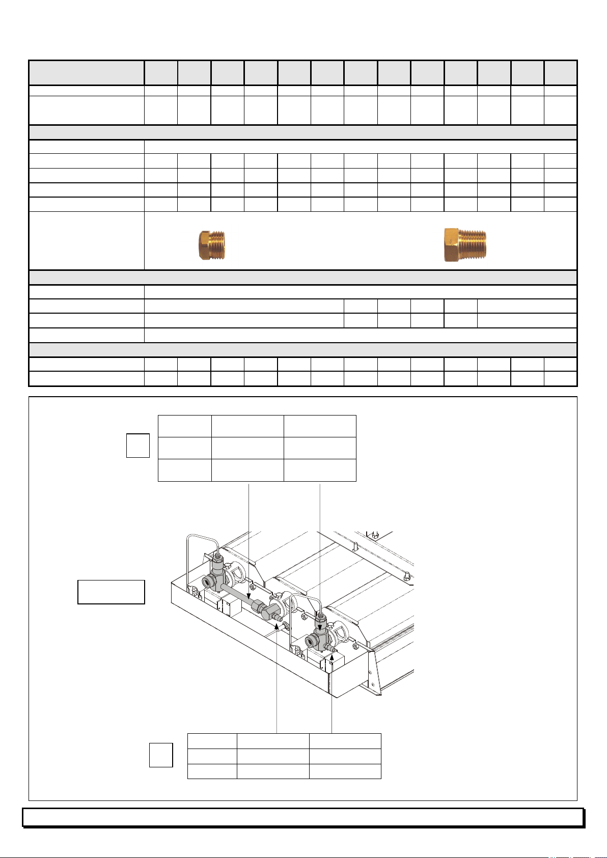
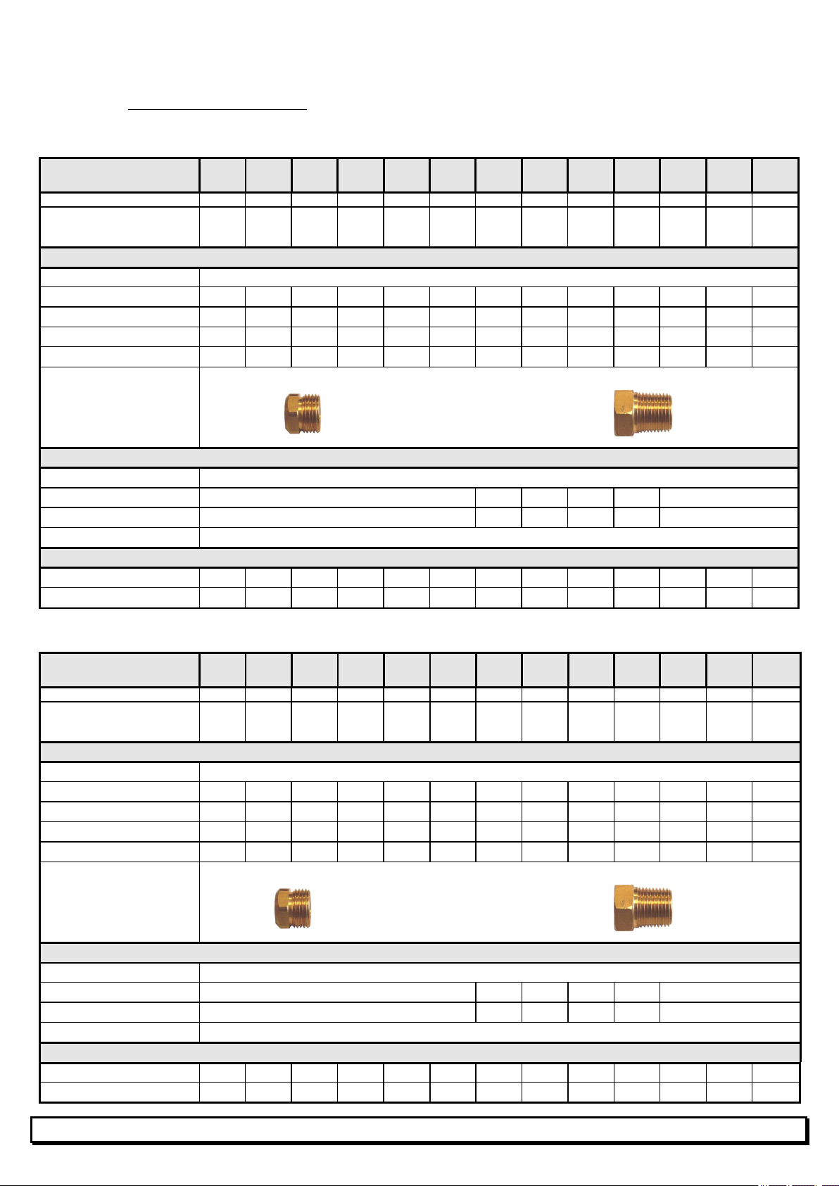
Gas input connection
Fitting G1/2" cylindrical (ISO 228-1) or Tapered fitting R1/2" conical (ISO 7-1)
ELECTRICITY
Power supply 230V (+10% -15%) - 50Hz Neutral mandatory
Consumption 0.1A 2x0.1A
0.1A 2x0.1A
0.1A 2x0.1A
Individual fuse 0.25A 2x0.25A
0.25A 2x0.25A
0.25A 2x0.25A
Ignition cycle length 45 seconds
VENTILATION
Combustion air (m3/h) 2.60 3.40 3.90 5.30 7.00 7.90 7.90 10.50 10.50 13.90 13.90 21.00 27.80
Req. air change (m3/h) 25 33 38 51 67.5 76 76 102 102 135 135 202.5 270
GAZ : G31 (Propane) - Category : I3P
MODEL
SX
SX
SX
SX
SX
SX
2SX
SX
2SX
SX
2SX
2SX
2SX
Weight (kg) 2.5 2.9 3.1 3.4 4.1 5.0 5.0 5.5 5.5 6.7 6.7 9.4 12.2
Net calorific value
Qn (kW) Hi 2.50 3.30 3.80 5.10 6.75 7.60 7.60 10.20 10.20 13.50 13.50 20.25 27.00
GAS
Inlet pressure 37 mbar
Injection pressure (mbar) 34.0 21.0 21.0 28.0 37.0 21.0 21.0 27.5 28.0 34.0 37.0 (See B)
34.0
Gas consumption (kg/h) 0.195 0.260 0.300 0.400 0.530 0.595 0.595 0.800 0.800 1.055 1.055 1.590 2.110
Ø prim. Inject. (1/100 mm) 155 140 130 180 - 185 2x130 240 2x180 370 - (See A)
2x370
Ø sec. Inject. (1/100 mm) 82 105 110 125 135 2x110 2x110 2x125 2x125 2x135 2x135 (See A)
4x135
Gas input connection
Fitting G1/2" cylindrical (ISO 228-1) or Tapered fitting R1/2" conical (ISO 7-1)
ELECTRICITY
Power supply 230V (+10% -15%) - 50Hz Neutral mandatory
Consumption 0.1A 2x0.1A
0.1A 2x0.1A
0.1A 2x0.1A
Individual fuse 0.25A 2x0.25A
0.25A 2x0.25A
0.25A 2x0.25A
Ignition cycle length 45 seconds
VENTILATION
Combustion air (m3/h) 2.30 3.10 3.60 4.80 6.30 7.10 7.10 9.60 9.60 12.60 12.60 18.90 25.20
Req. air change (m3/h) 25 33 38 51 67.5 76 76 102 102 135 135 202.5 270