4
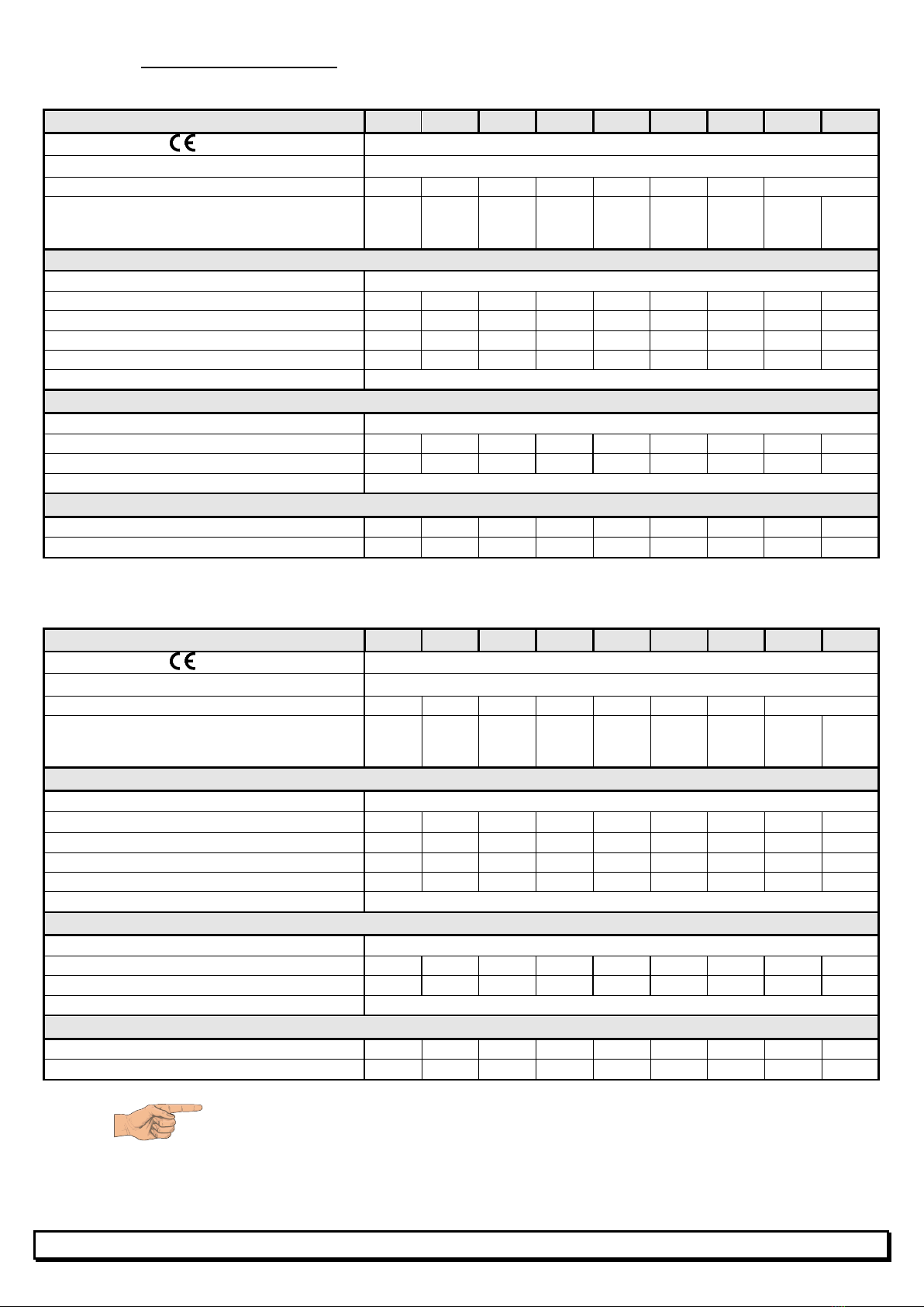
1.2 Technical specifications
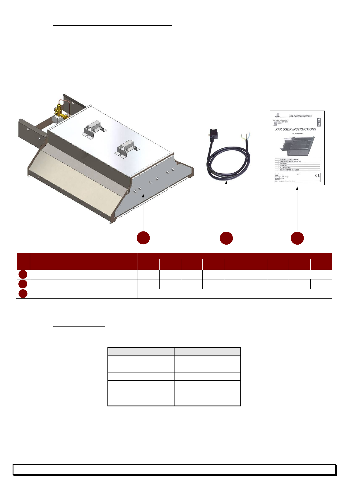
GAS : G20 (Natural gas) - Category : I2H GB/IE
MODEL XFR 16 XFR 20 XFR 20-2
XFR 24 XFR 24-2
XFR 32 XFR 32-2
XFR 48-2
XFR 64-2
Certificat number 1312 CL 5522
Class NOx 4
Weight (kg) 14.60 14.60 15.20 16.10 16.70 19.50 20.10 see page 10
Nominal heat input :
Net calorific value ΣQn (Hi) (kW)
Gross calorific value ΣQn (Hs) (kW)
5.80
6.44
6.65
7.38
6.65
7.38
8.00
8.88
8.00
8.88
10.30
11.44
10.30
11.44
2x 8.00
2x 8.88
2x 10.30
2x 11.44
GAS
Nominale inlet pressure p (mbar) 20
Injection pressure pi (mbar) 16 14 14 15 15 16 16 15 16
Volumetric flow rate (m
/h) 0.620 0.703 0.703 0.846 0.846 1.090 1.090 2x 0.846
2x 1.090
Orifice (injector) (1/100 mm) 1x179 2x152 2x152 2x171 2x171 2x179 2x179 4x171 4x179
Primary orifice (restrictor) (1/100 mm) 1x278 1x260 2x194 1x321 2x212 1x401 2x278 2x321 2x401
Gas input connection Fitting G1/2" cylindrical (ISO 228-1)
ELECTRICITY
Power supply 230V (+10% -15%) – 50Hz Neutral mandatory
Consumption (VA) 28 28 2x 28 28 2x 28 28 2x 28 2x 28 2x 28
Individual fast acting fuse 5x20 (RP3 – RP32) 0.25A 0.25A 2x 0.25A
0.25A 2x 0.25A
0.25A 2x 0.25A
2x 0.25A
Ignition cycle length 45 seconds maxi
VENTILATION
Combustion air (m
/h) 6.01 6.82 6.82 8.20 8.20 10.57 10.57 2x 8.20
2x 10.57
Required air change (m
/h) 58.0 66.5 66.5 80.0 80.0 130.0 103.0 2x 80.0
2x 103.0
GAS : G31 (Propane) - Category : I3P GB/IE
MODEL XFR 16 XFR 20 XFR 20-2
XFR 24
XFR 24-2
XFR 32 XFR 32-2
XFR 48-2
XFR 64-2
Certificat number 1312 CL 5522
Class NOx 4
Weight (kg) 14.60 14.60 15.20 16.10 16.70 19.50 20.10 see page 10
Nominal heat input :
Net calorific value ΣQn (Hi) (kW)
Gross calorific value ΣQn (Hs) (kW)
5.47
5.95
6.65
7.23
6.65
7.23
8.00
8.70
8.00
8.70
10.30
11.20
10.30
11.20
2x 8.00
2x 8.70
2x 10.30
2x 11.20
GAS
Nominale inlet pressure p (mbar) 37
Injection pressure pi (mbar) 34 28 30 32 32 32 34 32 32
Mass flow rate (kg/h) 0.429 0.543 0.543 0.654 0.654 0.841 0.841 2x 0.654
2x 0.841
Orifice (injector) (1/100 mm) 1x119 2x99 2x99 2x10⁶ 2x10⁶ 2x119 2x119 4x10⁶ 4x119
Primary orifice (restrictor) (1/100 mm) 1x225 1x174 2x134 1x251 2x172 1x275 2x225 2x251 2x275
Gas input connection Fitting G1/2" cylindrical (ISO 228-1)
ELECTRICITY
Power supply 230V (+10% -15%) – 50Hz Neutral mandatory
Consumption (VA) 28 28 2x 28 28 2x 28 28 2x 28 2x 28 2x 28
Individual fast acting fuse 5x20 (RP3 – RP32) 0.25A 0.25A 2x 0.25
0.25A 2x 0.25
0.25A 2x 0.25
2x 0.25
2x 0.25
Ignition cycle length 45 seconds maxi
VENTILATION
Combustion air (m
/h) 5.09 6.44 6.44 7.76 7.76 9.98 9.98 2x 7.76
2x 9.98
Required air change (m
/h) 54.7 66.5 66.5 80.0 80.0 103.0 103.0 2x 80.0
2x 103.0
Hight radiant factor, up to 0.85 (EN 419-2)