manuals.online logo
Brands
  1. Home
  2. •
  3. Brands
  4. •
  5. SCA
  6. •
  7. Lawn And Garden Equipment
  8. •
  9. SCA 131353 User manual

SCA 131353 User manual

1 2
PARTS LIST:
WARRANTY
This product is guaranteed against defects for a period of 12 months from date of
purchase. This warranty is provided by Super Cheap Auto Pty Ltd ACN 085 395
124 (Supercheap Auto) of 751 Gympie Rd Lawnton QLD 4501 Ph (07) 3482 7500.
Supercheap Auto will offer a repair, replacement product or store credit if the product
is assessed as being defective during the warranty period.
To claim under this warranty, take this product to the Front Service Desk of your nearest
Supercheap Auto store. For store locations, visit www.supercheapauto.com.au (AUS)
or www.supercheapauto.co.nz (NZ). You will need your receipt or proof of purchase.
Additional information may be requested of you to process your claim. Should you not
be able to provide proof of purchase with a receipt or a bank statement, identification
showing your name, address and signature may be required to process your claim.
This product may need to be sent to the manufacturer to assess the defect before
determining any claim. Faults or defects caused by product modification, misuse and
abuse, normal wear and tear or failure to follow user instructions are not covered under
this warranty.
Our goods come with guarantees that cannot be excluded under the Australian
Consumer Law. You are entitled to a replacement or refund for a major failure and
for compensation for any other reasonably foreseeable loss or damage. You are also
entitled to have the goods repaired or replaced if the goods fail to be of acceptable
quality and the failure does not amount to a major failure.
Any expenses incurred relating to the return of this product to store will normally have
to be paid by you. For more information contact your nearest Supercheap Auto store.
The benefits to the consumer given by this warranty are in addition to other rights and
remedies of the Australian Consumer Law in relation to the goods and services to
which this warranty relates.
ASSEMBLY INSTRUCTION WB7801
1
2
3
4
5
6
7
8
9
10
13
ILLUSTRATION A.
PLEASE NOTE THE ANGLE OF THE
BOLT HOLES ON HANDLE AND WEDGE
ILLUSTRATION B.
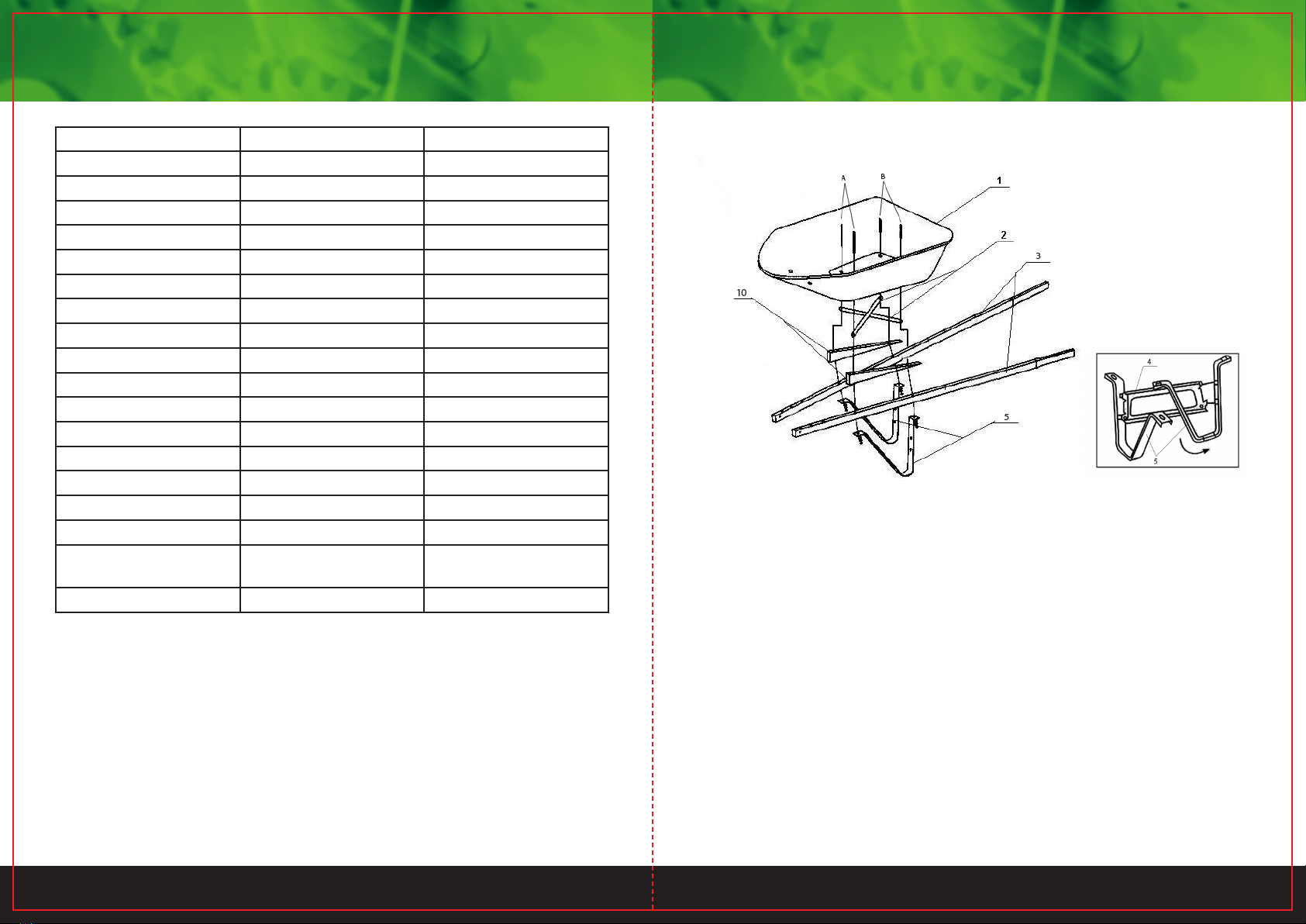
ACCESSORIES(CHECKLIST):
1)TRAY:1PCS
2)TRAY BRACKETS:2PCS
3)STEEL HANDLE:2PCS
4)LEG BRACE:1PCS
5)LEG:2PCS
6)AXLE BRACKET:2PCS
7)AXLE:1PCS
8)NOSE GUARD:1PCS
9)TRAY BRACE:2PCS
10)WEGES:2PCS
11)BOLTS&NUTS:12PCS
12)LOCK WASHER:12PCS
13)PNEUMATIC WHEEL:1PCS
PRE-ASSEMBLY
You will need a regular slotted screwdriver and a
wrench either box or open end or an adjustable
type,Although not necessary ,a pair of sawhorses
would be help full.A flat,level,clan assembly-
area is recommended.and we suggest all loose
bolts,nuts and washers be placed in a small con-
tainer during assembly.
ASSEMBLY
1.Place both handles(3).both wedges(10),and
plastic pad(2)on the bolt holes as shown in the
illustration A.
2.Place the tray(1)on the top of the plastic pad
/handle as shown in the diagram and align the bolt
holes with the corresponding holt boles in the
wedge/handle assembly.Insert one(11)bolt
through each of the front holes and one(11)
bolt through each of the rear holes.
3.Assembly the legs(5)on the bolts protruding
though the bottom of thr handles,and loosely
attach eith a lock washer and nut on each bolt
4.Engage leg brace(4) into slot on leg (L)and
rotate 1/4 turn to lock as shown in illustration
B.repeat procedure on the other side.
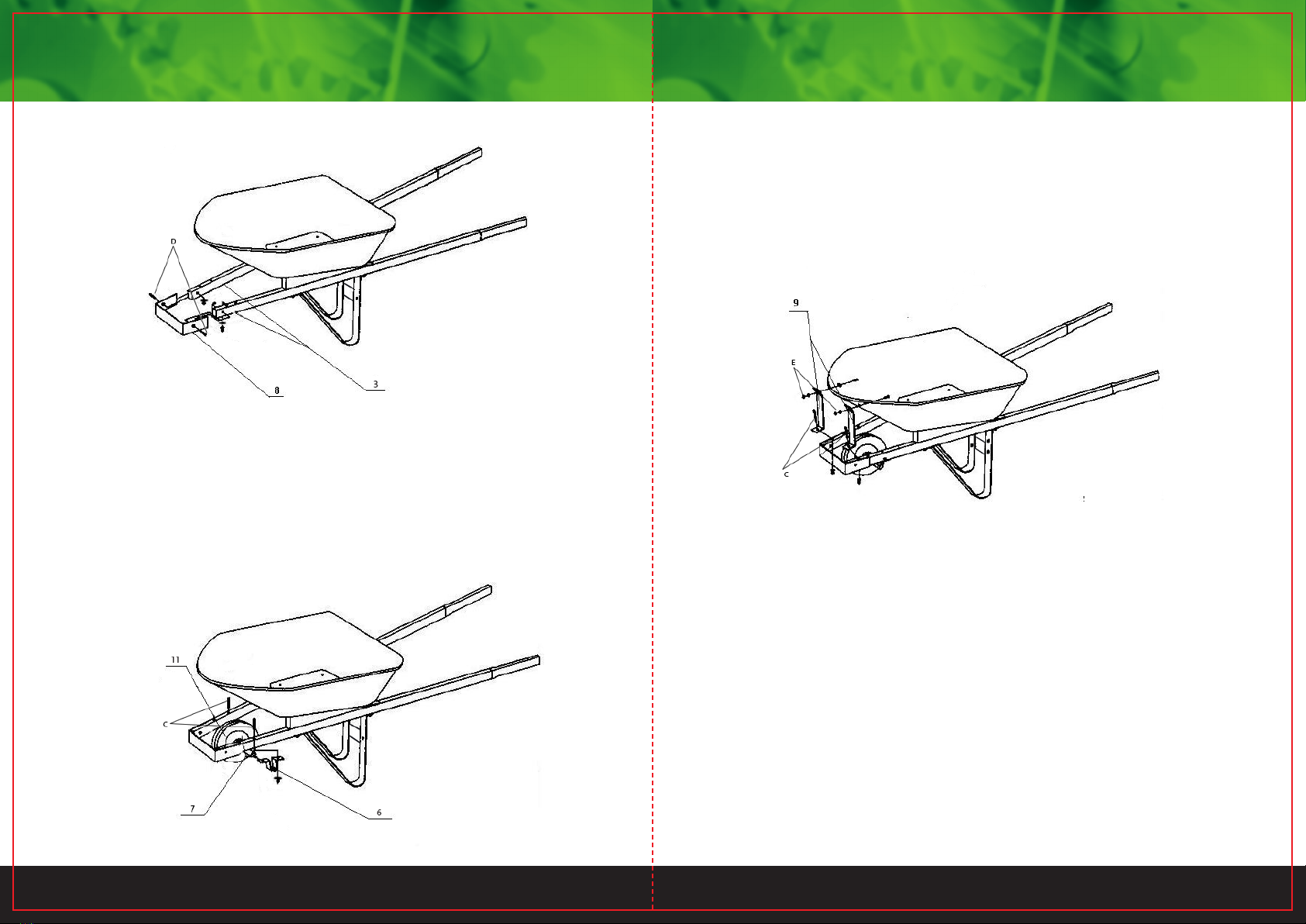
5.Attach the nose guard(8)to the outside of the
front of the handles using 2pieces of (11/12)
lock washers,and nuts.
6.Attached the top half of the 2 tray braces(9)to
the front of the tray as illustrated ,using 2 pieces
of bolts,lock washers,and nuts(11/12).
7.Insert the axle(7)through the wheel(13)
mount one axle bracket (6) on each end of th
axle.Hold this assembly in position under the
handles to make sure the holes align,if not
reverse the axle bracket left to right.
8.To attach the axle brackets(6)to the hand
insert 4 piecesof (11/12)bolts through the xx
in the top of the handles.Note that two of the(
/12)bolts will placed through the bottom x
holes of tray braces(9)(step 6)Assemble the
wheel/axle/axle bracket(step 7)X
bolts protruding from the bottom of the handX
using lock washers and nuts
9.TIGHTEN ALL NUTS SECURELY!
3 4
PART NO. DESCRIPTION QUANTITY
1 Tray 1
2 Tray Bracket 2
3 Handle 2
4 Leg Brace 1
5 Leg 2
6 Axle Bracket 2
7 Axle 1
8 Nose Guard 1
9 Tray Brace 2
10 Plastic Wedges 2
11 Pneumatic Wheel 1
A Bolt M8 X 135mm 2
B Bolt M8 X 85mm 2
C Bolt M8 X 70mm 4
D Bolt M8 X 40mm 2
E Bolt M8 X 20mm 2
F Locking Nut and Washer
8mm
12
G Washer 16mm 2
NOTE: Do not completely tighten bolts until the assembly is completed. For
easier assembly, we recommend two people assemble this product.
ASSEMBLY:
STEP 1:
1. Carefully take all parts out of the box and place them on a smooth flat
surface.
2. Position the TRAY (Part 1) at an angle so that the underneath is easily
accessible and insert bolts (A) and (B) through the tray.
3. Cross the TRAY BRACKETS (Part 2) as shown in the diagram and then slide
them over the bolts until they are against the bottom of the TRAY.
4. Slide the PLASTIC WEDGES (Part 10) over the bolts and against the bottom
of the TRAY BRACKETS. This PLASTIC WEDGE is a right triangle, make
sure the thicker part of the PLASTIC WEDGE is towards the front of the
wheelbarrow and the right-angle side is attached to the HANDLE.
5. Engage LEG BRACES (Part 4) into slots on LEGS (Part 5) as shown in image
A.
6. Place the HANDLE (PART 3) and LEG over the bolts.
7. Secure the parts with 4 Locking nuts and washers (F) on the 4 bolts.
Image A
5 6
13. Insert the AXLE (Part 7) into one AXLE BRACKET (Part 6), through the
WHEEL (Part 11), add 2 Washers (G) on the each side of the wheel, then into
the other AXLE BRACKET.
14. Insert Bolts (C) into the second hole on the HANDLE, and through the AXLE
BRACKET, and then secure the bolts with 2 Locking nuts and washers (F).
STEP 4:
16. Insert Bolts (C) through first hole on the TRAY BRACE (Part 9) and the hole
in the HANDLE, and then through the AXLE BRACKET, and secure on the
bottom of the HANDLE with 2 Locking nuts and washers (F).
17. Insert Bolts (E) into the holes in the TRAY and through the hole on the TRAY
BRACE and secure them with 2 Locking nuts and washers (F) on the outside
of the TRAY.
19. When assembly is completed, tighten all bolts.
STEP 2:
9. Slide the NOSE GUARD (Part 8) over the open end of the HANDLE.
10. Make sure the hole on the side of the NOSE GUARD align with the hole
on the HANDLE.
11. Insert Bolts (D) through the NOSE GUARD and then into the HANDLE.
12. Secure the HANDLE and NOSE GUARD with 2 Locking nuts and washers
(F) on the 2 bolts.
STEP 3:

Popular Lawn And Garden Equipment manuals by other brands

Ikra IEVL 1532 operating instructions

Ikra

Ikra IEVL 1532 operating instructions

Superior Sheffield quick start guide

Superior

Superior Sheffield quick start guide

X-METAL 44988 Assembly instructions

X-METAL

X-METAL 44988 Assembly instructions

ECOSURE RAISED BEDS Assembly guide

ECOSURE

ECOSURE RAISED BEDS Assembly guide

FRAME IT ALL Topolski 8' x 8' Assembly instructions

FRAME IT ALL

FRAME IT ALL Topolski 8' x 8' Assembly instructions

SNOWJOE AQUAJOE AJPGH50-DWS-RM instructions

SNOWJOE

SNOWJOE AQUAJOE AJPGH50-DWS-RM instructions

Poulan Pro PEM4N21RH instruction manual

Poulan Pro

Poulan Pro PEM4N21RH instruction manual

Glasswelt GARLAND SCAR 302 E instruction manual

Glasswelt

Glasswelt GARLAND SCAR 302 E instruction manual

Vegepod Small Trolley Stand Assembly instructions

Vegepod

Vegepod Small Trolley Stand Assembly instructions

FLORABEST FHV 32 A16 TRANSLATION OF ORIGINAL INSTRUCTIONS

FLORABEST

FLORABEST FHV 32 A16 TRANSLATION OF ORIGINAL INSTRUCTIONS

nutritower Vertical Hydroponic Indoor Garden Assembly and maintenance guide

nutritower

nutritower Vertical Hydroponic Indoor Garden Assembly and maintenance guide

BFG Technologies Grower Select Expanded Metal Bench Top Assembly manual

BFG Technologies

BFG Technologies Grower Select Expanded Metal Bench Top Assembly manual

Kasco 2400EAF Operation & maintenance manual

Kasco

Kasco 2400EAF Operation & maintenance manual

Toro 22602THD Operator's manual

Toro

Toro 22602THD Operator's manual

Clarke CHC90 Assembly instructions

Clarke

Clarke CHC90 Assembly instructions

Blumfeldt 10031119 manual

Blumfeldt

Blumfeldt 10031119 manual

Stinger UV-15 owner's manual

Stinger

Stinger UV-15 owner's manual

Behlen Country 80900190 Assembly, operation & maintenance instructions

Behlen Country

Behlen Country 80900190 Assembly, operation & maintenance instructions

manuals.online logo
manuals.online logoBrands
  • About & Mission
  • Contact us
  • Privacy Policy
  • Terms and Conditions

Copyright 2025 Manuals.Online. All Rights Reserved.