Scalys GrapeBoard User manual

1
GrapeBoard
User Manual

www.scalys.com
Overview
GrapeBoard
™
is a credit-card sized Secure Networking Communication Device, used in sen-
sor gateways, communication hubs and secure edge devices. GrapeBoard
™
is based on the
NXP® LS1012A, a 64-bit ARM® v8 network processor with network packet acceleration.
GrapeBoard
™
contains a single ARM
®
Cortex-A53 based processor running up to 1 GHz, a
hardware packet forwarding engine and high-speed interfaces. Also, the module incorporates
the same Trust Architecture and software compatibility of higher-tier QorIQ
™
Layerscape based
modules, enabling scalable, secure applications that leverage a common 64-bit ARM
®
v8 based
software.
Rich industrial interfaces
The GrapeBoard
™
provides an excellent base for high-performance, reliable, secure and efficient
networking with interfaces such as:
• 2x 1 GbE
• M.2 connector (supports single lane PCI or, SATA and USB 3.0)
• 2x USB 3.0/2.0
• 2.4 GHz Wi-Fi/BLE 4.0
• 1x I2C, anti-tamper
The GrapeBoard™ Industrial grade version will also be supported for long-term availability.
Scalable Performance
The product is based on the Raspberry PI
™
3+ formfactor and is compatible with a broad range
of standard RaspberryPI
™
3+ add-on boards (Hats) available on the market today. The comfort,
quality and design safety of a standard board solution is combined with the flexibility of a full
system design. You can realize this full system design by adding an application specific shields
or arrange an optimized custom design by Scalys.
ESD
Please be informed that your GrapeBoard
™
is a sophisticated piece of
sensitive micro-electronics. Electronic circuits are sensitive to electro static
discharge (
ESD
). Make sure to take ESD protective measures when the
GrapeBoard is not in a suitable enclosure.
Rev Date Description
1.0 17th Mai, 2018 First published version
Copyright © 2018, Scalys BV Public 2

www.scalys.com
User Manual
May 17, 2018
Contents
List of Tables 4
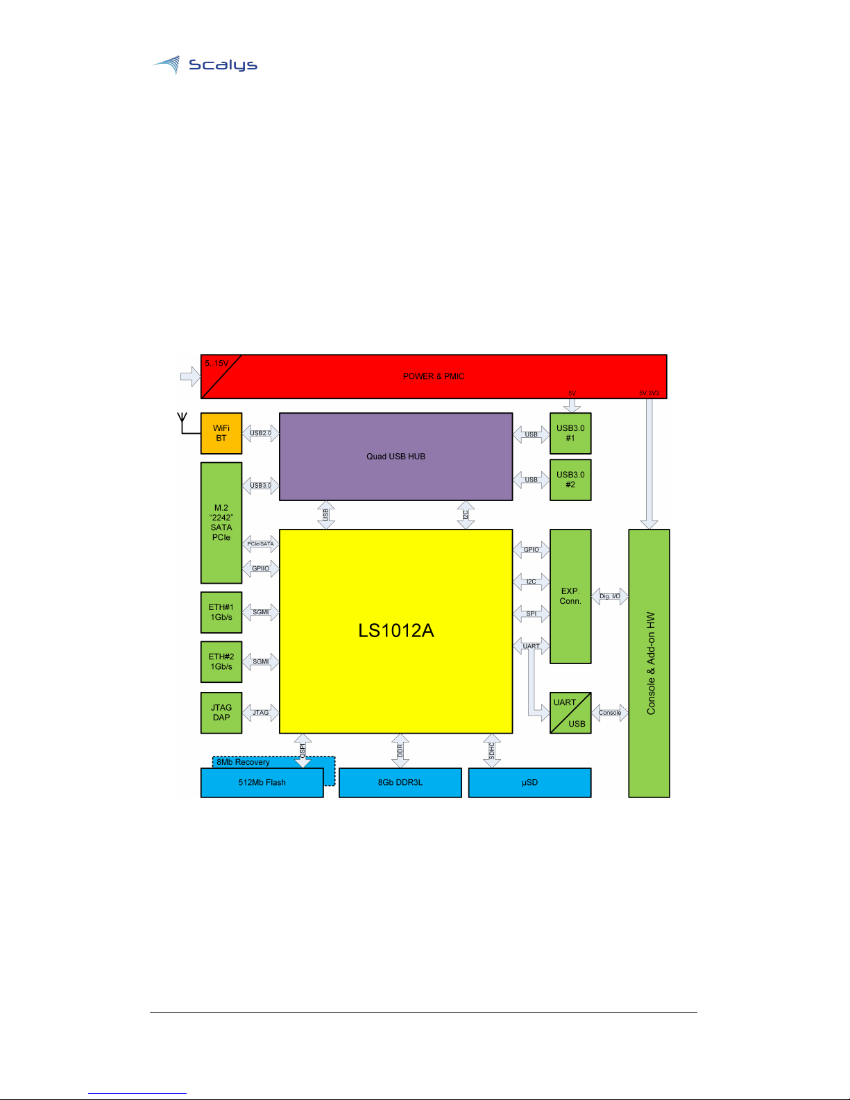
1 GrapeBoard™ features 5
1.1 Block diagram ........................................ 5
1.2 Feature List ......................................... 6
1.2.1 Main board components .............................. 6
1.2.2 Interfaces ...................................... 6
2 Board overview 7
2.1 Mechanical drawing .................................... 7
2.2 Mounting holes ....................................... 7
2.3 Connectors .......................................... 9
2.3.1 Buttons and LEDs ................................. 11
3 Electrical Specification 12
3.1 Supply voltage ........................................ 12
3.2 Power specification ..................................... 12
3.3 Temperature specification ................................. 12
4 Interfaces 13
4.1 SERDES options ....................................... 13
4.2 I2C.............................................. 13
4.2.1 Raspberry PI™ connector ............................. 14
4.2.2 JTAG ......................................... 14
4.2.3 WiFi/ Bluetooth ................................... 15
4.2.4 Tamper ........................................ 16
4.2.5 Boot device ..................................... 16
4.2.6 Boundary scan ................................... 16
4.2.7 Ethernet ....................................... 16
4.2.8 USB2.0-B micro ................................... 17
4.2.9 PWR_IN connector ................................. 17
4.2.10 PWR for industrial use ............................... 17
4.2.11 SDHC ........................................ 17
4.2.12 USB 3.0 ........................................ 17
4.2.13 M.2 Socket ...................................... 18
4.2.14 Board reset ...................................... 18
4.2.15 Push button for recovery boot operation .................... 19
5 Board Support Package 20
A References 21
B List of Acronyms 22
Copyright © 2018, Scalys BV Public 3

List of Tables www.scalys.com
List of Tables
2.1 Signal group ........................................... 10
2.2 buttons and LEDs ........................................ 11
4.1 SERDES configuration ..................................... 13
4.2 Raspberry PI™ connector ................................... 15
4.3 M.2 supported cards ...................................... 19
4.4 M.2 configuration pins ..................................... 19
Copyright © 2018, Scalys BV Public 4

www.scalys.com
User Manual
May 17, 2018
1
GrapeBoard™ features
1.1 Block diagram
The block diagram of the GrapeBoard™ is depicted in Figure 1.1.
Figure 1.1: Block Diagram
Copyright © 2018, Scalys BV Public 5

Chapter 1. GrapeBoard™ features www.scalys.com
1.2 Feature List
1.2.1 Main board components
The module contains the following on board main components:
- NXP® QorIQ LS1012A Processor
- Flash 512Mb and 8Mb recovery
- DDR3L 8Gb
- USB hub
1.2.2 Interfaces
The module contains the following interfaces:
- 5-15VDC pluggable power supply connectors
- Dual IEEE 802.3 1000BASE-T Gigabit Ethernet ports
- Dual USB 3.0-Compliant DS ports
- USB serial console interface
- M.2 "B-key 2242" interface connector
- eSDHC card slot
- 26-pin add-on board connector
- SMA antenna connector for WiFi/BT
- Push button for recovery boot operation
- Tamper detect input
- Reset button
- JTAG DAP connector
Copyright © 2018, Scalys BV Public 6

www.scalys.com
User Manual
May 17, 2018
2
Board overview
This chapter describes the mechanical specifications and positions of mounting holes, connectors,
headers, jumpers, buttons and LEDs available on the GrapeBoard
™
. Pin descriptions for headers
can be found in chapter 4.
2.1 Mechanical drawing
The mechanical dimensions are shown in Figure 2.1. All dimensions are in mm.
Figure 2.1: Mechanical Dimensions
2.2 Mounting holes
The positioning of the mounting holes is depicted in Figure 2.2. The non lated mounting holes
have a diameter of 2.9mm ±0.1mm.
Copyright © 2018, Scalys BV Public 7

Chapter 2. Board overview www.scalys.com
Figure 2.2: Overview of mounting holes position on top
Copyright © 2018, Scalys BV Public 8

Chapter 2. Board overview www.scalys.com
2.3 Connectors
The positioning of the connectors is depicted in Figure 2.3 and Figure 2.4. The pin 1 is marked
with a dot in the silkscreen for connectors 1 and 2, which is depicted with a red dot near the
connectors in Figure 2.3.
Figure 2.3: Overview of connector positioning on top
Figure 2.4: Overview of connector positioning on bottom
Copyright © 2018, Scalys BV Public 9

Chapter 2. Board overview www.scalys.com
Table 2.1: Signal group
Number Connector
1 Raspberry PI™ expansion
2 JTAG
3 SMA connector for WiFi/BT antenna
4 Tamper
5 Boot device select
6 Boundary scan
7 Ethernet 1
8 Ethernet 0
9 Serial console
10 PWR IN
11 PWR IN for industrial use
12 SDHC
13 USB3.0-A
14 M.2
Copyright © 2018, Scalys BV Public 10

Chapter 2. Board overview www.scalys.com
2.3.1 Buttons and LEDs
The positions of the buttons and LEDs on the GrapeBoard™ are depicted in Figure 2.5
Figure 2.5: Overview of button and LED positioning
Table 2.2: buttons and LEDs
Number Component
1 Reset button
2 Recovery button
3 Power LED
4 SATA active LED
5 USB fault LED
Copyright © 2018, Scalys BV Public 11

www.scalys.com
User Manual
May 17, 2018
3
Electrical Specification
3.1 Supply voltage
The GrapeBoard
™
requires an external power supply. There are two option available to connect
the power supply, marked as 10 and 11 in Figure 2.3. Further details about these power connec-
tions are described in section 4.2.9 and section 4.2.10.
Any input voltage between 5.0 and 15.0VDC is valid. The power LED indicates that power is
available. Highly efficient switch-mode voltage converters will convert the generic input voltage
to the specific required individual board- or interface voltages.
Note:
The power supply including ground connection must be connected before other interfaces
are connected.
Please take notice of the power connector polarity and maximum input voltage! Reverse po-
larization or an input voltage over 16VDC will permanently damage your GrapeBoard™.
The
inner conductor of the barrel connector shall be connected to the positive- or plus-pole. The
right most pin of the Molex
TM
connector when viewed from the antenna side of the board is the
positive- or plus-pole.
Due to power limitations of the USB2.0 port, the GrapeBoard™ does not support powering
from the USB2.0 micro-B connector.
3.2 Power specification
Power consumption depends the application and utilized board interfaces. Scalys offers an
accessories pack, which includes a suitable CE certified power supply and WiFi antenna.
The standard 12V/1A power supply can provide power to all interfaces and electronic compo-
nents.
3.3 Temperature specification
The GrapeBoard is available in commercial operating temperature grade, 0
°
C to +70
°
C. Industrial
temperature grade available upon request.
Copyright © 2018, Scalys BV Public 12

www.scalys.com
User Manual
May 17, 2018
4
Interfaces
This chapter describes the interfaces available on the GrapeBoard
™
. For the location of the
connectors see Figure 2.3
4.1 SERDES options
The LS1012A supports three SerDes lanes (SRDS_PRTCL_S1RCW[128:143]=3308), connected as
follows:
Table 4.1: SERDES configuration
SERDES Interface Device
SD A SGMII Ethernet PHY1
SD B SGMII Ethernet PHY2
SD D SATA/PCIe M.2 slot
For more information on Serializer/Deserializer (
SERDES
)options and their configuration refer
to the QorIQ LS1012A Reference Manual [1].
4.2 I2C
A block diagram of the I
2
C bus on the GrapeBoard
™
module is schematically depicted in
Figure 4.1
Figure 4.1: I2C Block diagram
Copyright © 2018, Scalys BV Public 13

Chapter 4. Interfaces www.scalys.com
4.2.1 Raspberry PI™ connector
A raspberry PI
™
expansion connector, 26 pins 2.54mm pitch, is available. The pinout of the
connector is specified in Table 4.2.
Figure 4.2: Raspberry Pi™ pinout
The raspberry PI
™
expansion connector comprises of a number of different interfaces. They are:
• Four GPIO pins
• I2C interface pins
• SPI interface pins
• UART Receive- and Transmit Data pins
All signals are 3.3V. All pins are buffered with bidirectional buffers, which do not need any
configuration. The I2C interface uses the PCA9306, the other interface TXS0108. Please consult
the respective datasheets for more information.
Note
: None of the pins are considered rugged interface signals. Pin abuse by sourcing or sinking
too much current or by applying too high voltages will damage your GrapeBoard
™
permanently.
You are interfacing directly to sensitive electronics.
4.2.2 JTAG
There is one JTAG, mini-10 pole 2X5 IDC 1.27mm, connector (X10) placed on the PCB. The pin-out
complies to the ARM Cortex 10-pin JTAG standard and uses pin 9 as the JTAG HW detection
signal.
Note
: The pin-1 location is marked by a tiny white dot on the PCB. The through hole type pin
header has no polarization key to prevent incorrect positioning.
For more information on using the JTAG chain, please contact Scalys.
Copyright © 2018, Scalys BV Public 14

Chapter 4. Interfaces www.scalys.com
Table 4.2: Raspberry PI™ connector
Pin RPi model-B 7Reference to LS1012A 1Power rail Direction
Signal names package pin number
(pin name)
1 +3V3 2- 3v3 Out
2 +5V0 3- 5v Out
3 I2C_SDA 458 3v3 I/O
4 +5V0 3- 5v Out
5 I2C_SCL 4121 3v3 Out
6 GND - - -
7 GPCLK 25CLK - 3v3 Out
8 UART_TXD 583 3v3 Out (I/O)
9 GND 6- - -
10 UART RXD 516 3v3 In (I/O)
11 GPIO_17 7,8 125 (GPIO1_27) 3v3 I/O
12 GPIO_18 710 (GPIO2_04) 3v3 I/O
13 GPIO_27 777 (GPIO2_05) 3v3 I/O
14 GND - - -
15 GPIO_22 711 (GPIO2_06) 3v3 I/O
16 GPIO_23 778 (GPIO2_07) 3v3 I/O
17 +3V3 2- 3v3 Out
18 GPIO_24 779 (GPIO2_09) 3v3 I/O
19 SPI_MOSI 65 3v3 Out (I/O)
20 GND - - -
21 SPI_MISO 63 3v3 In (I/O)
22 GPIO_25 713 (GPIO2_10) 3v3 I/O
23 SPI_CLK 127 3v3 Out (I/O)
24 N_SPI_CE0 126 3v3 Out (I/O)
25 GND - - -
26 N_SPI_CE1 64 3v3 Out (I/O)
1Peripheral pin mapping may require re-mapping at LS1012A BSP level.
2Load current grand total of all 3.3V pins shall not exceed 0.5A.
3Load current grand total of all 5.0V pins shall never exceed 0.5A.
Overloading will cause 5.0V supply to fail at startup.
4SDA and SCL lines have 4k7 on-board pull up resistors and do not require
external pull ups.
5UART signals are shared between USB/UART bridge and GPIO connector
6For proper signal- and power integrity, use all GND connections, especially
when using external SPI at clock frequencies over 10MHz.
7Only the default configuration is mentioned. For other configurations, refer
to [1].
8
If SPI mode is selected(factory RCW default), GPIO_17 defaults to SPI_CS2_B.
4.2.3 WiFi/ Bluetooth
On the GrapeBoard
™
a WiFi and Bluetooth (
BT
) combination module (F23BUUM13-W2) is
present. This module is accessible through the USB hub on port 4 hub and communicates through
USB2.0 compatible bus signals.
The module complies to:
• WiFi: IEEE 802.11b,g,n
• BT: V2.1+EDR/Bluetooth 3.0/4.0
A WiFi or
BT
antenna must be connected to the reverse polarity SMA connector marked as 3 in
Figure 2.3. The external antenna shall not have a maximum gain over +5dBi. A 3dB on-board
attenuator will limit the maximum ERP to within the applicable limits as dictated by the FCC
modular approval letter.
Copyright © 2018, Scalys BV Public 15

Chapter 4. Interfaces www.scalys.com
Scalys offers an accessories pack, which includes WiFi antenna and a CE certified power supply.
4.2.4 Tamper
The LS1012A tamper detect pin "GPIO2_17/TA_TMP_DETECT_B "is available through a dedi-
cated 2-pin header marked "TMPR". One pin is connected to ground and the other to the tamper
detect pin. The active low tamper detect signal has an on-board 4k7 pull up resistor to the 1.8V
rail. Tamper can be triggered by shorting the tamper detect signal pin and the ground pin by
means of a mechanical switch or an open-drain or open-collector output. Any voltage applied to
the tamper detect input pin over 1.8V will damage your GrapeBoard™.
note
: "real life" tamper circuitry should use pull down, not pull up, for a fail safe implementation.
Figure 4.3: Tamper implementation
4.2.5 Boot device
This header selects the source for the Reset Configuration Word (
RCW
) data. By default (no
jumper placed) the 512Mb QSPI NOR flash is selected as boot device.
By placing a jumper the hardcoded
RCW
option is chosen. This option can be useful if the board
has no valid
RCW
present or if the customer is unable to load in the
RCW
from a non-volatile
memory. Refer to the LS1012A Reference Manual (
RM
) for more information on power-on-reset
configuration.
4.2.6 Boundary scan
Boundary scan is used for production purposes only. For more information contact Scalys.
4.2.7 Ethernet
Each Serdes SGMII interface is connected to a Texas Instruments
TM
PHY’s DP83867. It interfaces
directly to twisted pair media through an external transformer. Several functions can be multi-
plexed onto the LEDs for different modes of operation. For more details refer to components data
sheet
Copyright © 2018, Scalys BV Public 16

Chapter 4. Interfaces www.scalys.com
4.2.8 USB2.0-B micro
The USB2.0-B interface is solely intended to connect externally to UART1 of the LS1012A pro-
cessors DUART peripheral. It consists of an USB to UART bridge (Silicon LabsVirtual Com Port
CP2102N) that is enabled as soon as an active micro USB cable is plugged in. If there is no active
USB cable plugged in, UART1 is also routed to the expansion connector.
note
: the UART1_SIN receive data pin contains the combined (logical AND) data of both UART
RXD signal paths(Expansion connector and USB2). Connect just one serial communication device
to your GrapeBoard™ either through the USB2 connector or through the expansion connector.
The default data format is:
• Baud rate 115k2
• 8 data bits
• No parity
• Single stop bit
4.2.9 PWR_IN connector
The power supply from the accessories pack can be plugged into the board connector marked
"PWR_IN" in the lower left hand corner of the board. The recommended mating plug outer
diameter is 5.5mm and the maximum insertion depth is 8.3mm accommodating almost all
standard 2.5mm barrel connectors.
The inner conductor of the barrel connector shall be connected to the positive- or plus-pole. As
depicted in Figure 4.4
Figure 4.4: Schematic representation of the barrel connector polarity
4.2.10 PWR for industrial use
For a more permanent type of power supply connection the 2.54mm Molex KK
TM
connector,
with friction ramp to prevent accidental detachment, can be used. The corresponding Molex
TM
pluggable counterpart is 22-01-2027. The right most pin of the Molex
TM
connector when viewed
from the antenna side of the board is the positive- or plus-pole.
4.2.11 SDHC
A SDHC "high speed" micro-SD is connected to the LS1012A eSDHC1 peripheral.
4.2.12 USB 3.0
For support of USB3.0, a Cypress
TM
CYUSB3304-68LTXC HX3 family member USB3.0 4-port Hub
is used. HX3 is a family of USB 3.0 hub controllers compliant with the USB 3.0 specification revi-
sion 1.0. HX3 supports SuperSpeed (
SS
), Hi-Speed (
HS
), Full-Speed (
FS
), and Low-Speed (
LS
) on
Copyright © 2018, Scalys BV Public 17

Chapter 4. Interfaces www.scalys.com
all the ports.
The port allocation is as follows:
• Port 1 : Lower USB3.0 socket for external use
• Port 2 : Upper USB3.0 socket for external use
• Port 3 : M.2 interface for external use
• Port 4 : WiFi/BT RF module for internal use in USB2 mode
USB Hub configuration shall be performed over the I2C bus as in "I2C external master" mode. The
HX3 I2C slave address (7 bits) is 0x60. Please note that I2C signals are shared between on-board
peripherals and the GPIO Expansion connector as depicted in Figure 4.1. Already used on-board
I2C addresses cannot be used again externally.
Power control and port power overload are shared between both USB3.0 sockets. Current drawn
from USB3.0 sockets shall be limited to 500mA. Both USB3.0 ports support only 5V.
When an over-current or over-temperature shutdown condition is encountered the USB-FLT LED
will light up.
4.2.13 M.2 Socket
The "B-key, socket-2"M.2 socket on the bottom side of the board offers the following interfaces:
• PCIe: single lane
• SATA rev. 3.0
• USB3.0
• SMBus
Pin-out information can be found in the PCI SIG documentation [
2
]. For Electro-mechanical
information refer to [3]
The SATA active LED illuminates on SATA activity.
Supported cards
The cards (mechanical key B) that are supported by the LS1012A module are listed in Table 4.3.
All configuration pins CFG[0:3] can be read and decoded by LS1012A CPU to recognize the
indicated module configuration and host interface supported. On the PCB side, each of the
CFG[0:3] signals are fitted with a 11Kohm pull-up resistor. For module configuration refer to [
3
]
Note
: The SATA and PCIe interface cannot be used simultaneously and interface type is de-
termined by the serdes settings which are controlled by the CPU. Refer to the QorIQ LS1012A
Reference Manual [1] for the RCW settings.
4.2.14 Board reset
Pushing button marked RST, button 1 in Figure 2.5, will initiate a hardware reset (POR).
Copyright © 2018, Scalys BV Public 18

Chapter 4. Interfaces www.scalys.com
Table 4.3: M.2 supported cards
Type Width Length Component height (top/bot) Supported interfaces 1
2242-S1-B 22mm 42mm 1.2mm / 0mm PCIe x1/ USB2.0 / USB 3.0 / SATA / I2C
2242-S2-B 22mm 42mm 1.35mm /0mm PCIe x1/ USB2.0 / USB 3.0 / SATA / I2C
2242-S3-B 22mm 42mm 1.5mm /0mm PCIe x1/ USB2.0 / USB 3.0 / SATA / I2C
2242-D4-B 22mm 42mm 1.5mm /0.7mm PCIe x1/ USB2.0 / USB 3.0 / SATA / I2C
2242-S1-M 22mm 42mm 1.2mm / 0mm PCIe x1/ SATA / I2C
2242-S2-M 22mm 42mm 1.35mm /0mm PCIe x1/ SATA / I2C
2242-S3-M 22mm 42mm 1.5mm /0mm PCIe x1/ SATA / I2C
2242-D4-M 22mm 42mm 1.5mm /0.7mm PCIe x1/ SATA / I2C
1PCIe x1 or SATA supported, these interfaces cannot be used simultaneously
Table 4.4: M.2 configuration pins
Config pin M.2 CPU GPIO
CFG0 GPIO2_12
CFG1 GPIO2_11
CFG2 GPIO2_13
CFG3 GPIO2_14
4.2.15 Push button for recovery boot operation
The LS1012A can boot from 2 on-board memory sources . The standard source is the 512Mb NOR
flash. The other is the 8Mb "recovery" NOR flash.
By pressing and holding down the button marked "REC", button 2 in Figure 2.5, and power
cycling the GrapeBoard
™
, the LS1012A will execute a recovery operation offering the possibility
to restore the standard flash with valid contents.
note
: the recovery button must remain pressed
until feedback is received via the UART1 of the LS1012A processor, which can be accessed via the
USB2.0-B micro connector, refer to 4.2.8 for more information on the USB2.0-B interface.
The recovery flash is read only.
Copyright © 2018, Scalys BV Public 19

www.scalys.com
User Manual
May 17, 2018
5
Board Support Package
The Board Support Package (
BSP
) provided for the GrapeBoard
™
is based on the BSP provided
by NXP
®
. Refer to the BSP user guide for information on obtaining, building and deploying the
BSP.
Copyright © 2018, Scalys BV Public 20
Table of contents