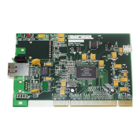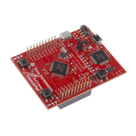
Micrel, Inc. SY88216L Optical Evaluation Board
February 2008 2 M9999-022108-
TOSA Installation
Check the pin-out of the laser and install according to
the diagrams shown in Figure 1.
Figure 1. Mounting of the Laser
Evaluation Board Setting and Operation
1. Install a jumper on SW3 to enable the driver.
2. Continuous Mode Operation: Connect BEN-
to GND or connect BEN+ to VCC to operate the
chip in continuous mode first.
3. Adjust potentiometers VR2 (BIASMAX), VR3
(MODSET), and VR4 (BIASSET) completely
counterclockwise to set bias and modulation
currents to zero “0” before powering the board.
4. If the inputs DIN+/DIN- are DC-coupled, set
the output of the pattern generator high level
within the range 0.5V-2V, first. Then connect
the input (DIN+/DIN-) to the output of the
pattern generator.
5. Connect the laser output to the optical module
of the scope with a SMF jumper.
6. Open Loop Operation: Install a jumper on
SW2 (MOD ON) and make sure that there is
no jumper on SW4 (PD-MD).
7. Connect 3.3V to TP9 (red) and GND to TP10
(black) to power the board.
8. Turn VR2 (BIASMAX) clockwise, BIASMAX
sets the bias current in open loop, to increase
the bias current until the laser starts output
some light then turn VR3 clockwise to set
modulation current. Keep adjusting bias (VR2)
and modulation (VR3) until an acceptable eye
diagram is seen on the scope.
9. Bias Current can be deduced from the voltage
across R7 between TP4 and TP6.
IBIAS = (VTP6 – VTP4) / R7
10. The voltage between TP11 (BIASMON) and
GND (across R4) is proportional to (Bias
Current + Half modulation current):
(IBIAS + IMOD / 2) / 50 = VR4 / R4
11. Close-loop operation: Install jumpers on SW1
(BIAS ON) and SW4 (PD-MD) to close the
loop and turn VR4 clockwise to increase the
bias current. Keep adjusting BIASSET (VR4)
and modulation (VR3) until an acceptable eye
diagram is seen on the scope.
Performance
Figure 2. Optical Eye Diagram
1.25Gbps with 2.3G Filter
Laser Response Tuning
Overshoot/Undershoot
The damping resistors R21 and R22 installed in series
with the laser are 10Ω. This value might be changed
to a higher value to minimize or suppress any
overshoot or undershoot on the optical signal out of
the laser, but keep in mind that higher value damping
resistors will lead to higher rise/fall time and lower
maximum modulation current.
The user can adjust the values of (R19, C8) and/or
(R8, C9) to get better performance with his laser.

