Scandium SC900UMS Owner's manual

INSTALLATION · OPERATION · MAINTENANCE GUIDE
UNDERMOUNT RANGEHOOD
SC900UMS

Page 2
Index
1. Welcome..........................................................................................................................................3
2. Before Installation............................................................................................................................4
Maintenance and Service...................................................................................................................................5
3. Maintenance and Service .................................................................................................................5
LED Bulb Replacement ......................................................................................................................................6
Electrical Cord.....................................................................................................................................................6
For Users..............................................................................................................................................................6
4. Description & Installation.................................................................................................................7
Rangehood Contents .........................................................................................................................................7
Operation............................................................................................................................................................7
Cutout Size..........................................................................................................................................................7
5. Installation .......................................................................................................................................8
Mounting Instructions ........................................................................................................................................8
For Installers........................................................................................................................................................8
Overhead Cabinet Rangehood Installation Position ......................................................................................9
Mounting Points ................................................................................................................................................10
Installation Example ...........................................................................................................................................11
Overview..............................................................................................................................................................12
Flexi Ducting .......................................................................................................................................................12
6. Condensation Information ...............................................................................................................13
Cooking with Induction Cooktops ....................................................................................................................13
7. Troubleshooting...............................................................................................................................14
Faulty Installation ...............................................................................................................................................14
Service ................................................................................................................................................................15
8. Specications...................................................................................................................................16
Dimensions..........................................................................................................................................................16
Technical Specications .....................................................................................................................................16
9. Disclaimer ........................................................................................................................................16

Page 3
1. Welcome
Welcome
Thank you for purchasing this Scandium appliance.
To achieve the optimal performance from your appliance, and to avoid the risk of accident or damage, it is
essential to read this manual before installation and rst time use.
This guide contains important information on the use and maintenance of the appliance, as well as important
safety notes.
Your appliance has been thoroughly checked for safety and functionality before being packaged and leaving
the manufacturer.
Please keep this instruction manual in a safe place so you can refer to it at any time.
ATTENTION
Installation, regulation or maintenance, of both gas and electric appliances, should
only be executed by qualied and authorised personnel who are aware of the
installation regulations in force.
Please make sure to read this booklet carefully, containing general instructions for the
Installation, Operation and Maintenance of your appliance, before installation and
operation.
It is extremely useful to know, in detail, the best way of operating and maintaining
this appliance so you can enjoy its benets and be assure of the best results.
Please keep this instruction booklet with the appliance in case you pass it on to
someone else.

Page 4
2. Before Installation
Important
• Upon collection or delivery of the appliance, any damage or defects MUST be reported within 48 hours to
the retailer or the customer service centre, or no claim will be recognised.
• Before installing the electrical connections, you should:
– Verify that the indicated electrical data coincides with the voltage values and frequency of the electrical
circuit in the house where the rangehood is to be installed.
– Check that the premises has electrical protection against short circuits and electrocution, pursuant to the
applicable legislation.
– Always switch off the power using the double-pole switch before maintenance and turn the power on
again for normal use only when the operation has been completed.
• DO NOT INSTALL THIS APPLIANCE IF YOU FIND IT DAMAGED.
• If this product is installed damaged, neither the supplier, nor the retailer, will be responsible for the costs
associated with the repair, replacement, removal or re-installation of the appliances.
• Please read the entire instruction manual before installing the rangehood.
• Always switch power off prior to installation. All electrical work must be carried out by a registered
electrician in accordance with local and national electrical codes as applicable. For your safety, this product
must be earthed.
• The power socket must be accessible and enable the end user to isolate the rangehood from the power for
the purpose of internal cleaning or maintenance.
• The power outlet must be within reach of the power cord from the rangehood.
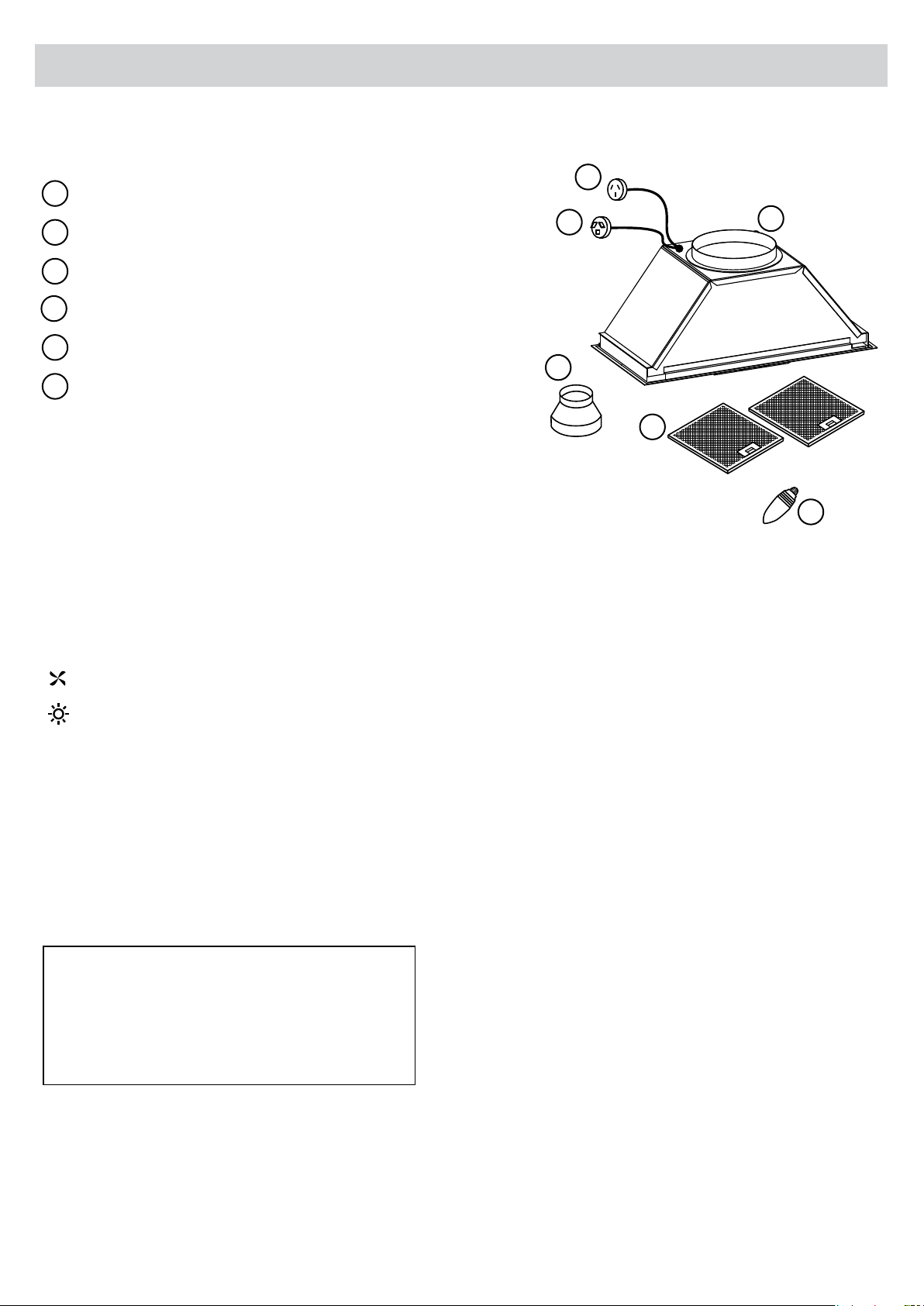
• Check all contents of the packaging, including all electrical functions of the rangehood before installation.
• The rangehood is heavy. Please ensure adequate care when installing to prevent personal injury.
• The rangehood is not intended for use by persons (including children) with reduced physical, sensory or
mental capabilities, or lack of experience and knowledge, unless they have been given supervision or
instruction concerning use of the appliance by a person responsible for their safety.
• Children must be supervised to ensure that they do not play with the appliance.
• The room must have adequate ventilation when the rangehood is used at the same time as appliances
burning gas or other fuels.
• There is a potential re risk if cleaning is not carried out in accordance with the instructions. You MUST read
the details concerning the method and frequency of cleaning.
• Do not ambé under the rangehood. This will void the warranty.
• Exhaust air must not be discharged into an existing ue which is used for exhausting fumes from appliances
burning gas or other fuels.
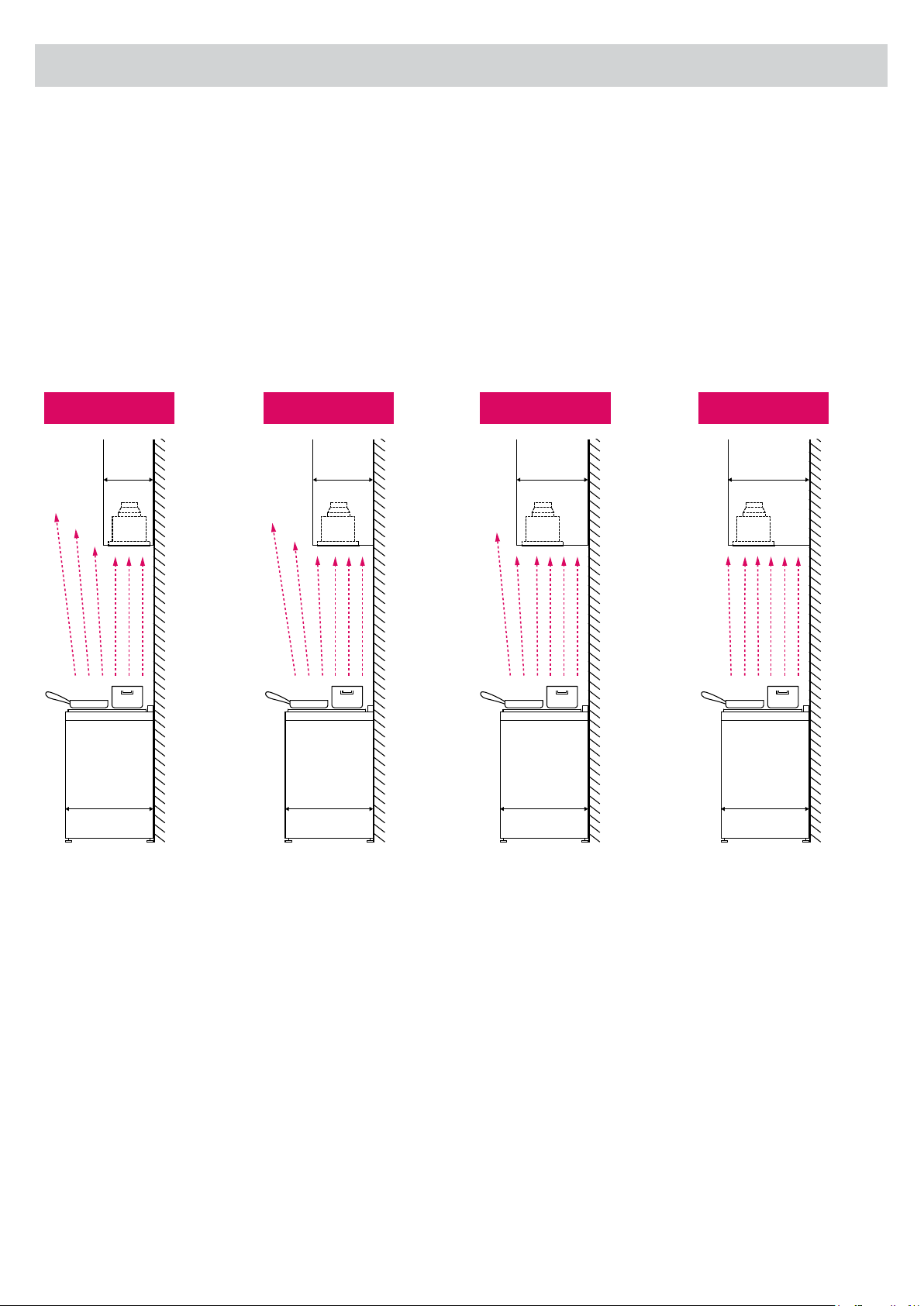
• The minimum distance between the hob surface and the lowest part of the rangehood is 650mm. This
distance should be at least 650mm, if the rangehood is installed over a gas hob. If the instructions for the
gas hob specify a greater distance, adhere to those instructions.
• Attention should be given to ensure that any applicable regulations concerning the discharge of exhaust air
is fullled. Even a partial obstruction will restrict the efciency of the rangehood.

Page 5
3. Maintenance and Service
• Stainless steel is very easily damaged during installation if scratched or knocked by tools. Protect the
rangehood with the cardboard box or a plastic bag during installation.
• CAUTION: Accessible parts may become hot when used with cooking appliances.
• This appliance must be installed and repaired by a qualied technician.
• It is dangerous to modify any part of this appliance. Modication of any kind, will void the warranty.
• The manufacturer declines all responsibility in case of failure to adopt proper safety measures.
• Please consult local laws and regulations and install in accordance.
• Use an electrical connector with earth that is correct for your location.
• Check that the voltage in your area corresponds to the appliance as indicated on the rating label.
• This appliance must be connected to an electrical supply with a ground connection.
• Check that the installation and electrical connections are made by a qualied technician and indicated
instructions and local regulations in force are met, using materials that are compliant with the applicable
legislation.
• The company will not be responsible for any installations executed by non-qualied persons and
installations that fail to heed the applicable legislation on electrical safety (with regard to both modes and
materials).
• The electrical technical data can be found inside the rangehood, after removing the grease lters.
• The exible power cable supplied is already connected internally and emerges from the rangehood near the
air outlet tube.
Maintenance and Service
• Cleaning and user maintenance shall not be made by children without supervision.
• Always switch off and disconnect power before cleaning.
• The rangehood surface should be cleaned with a soft cloth and non-corrosive detergent. Wash with warm
soapy water and a soft sponge. Never use abrasive detergent, scouring pads, steel wool or solvents on any
part of this appliance. Always make sure to dry the appliance after cleaning and never leave wet, as this will
cause irreparable damage.
• Clean the interior of the rangehood with a damp cloth and a neutral detergent or methylate spirits.
• For better results, you can use a high quality cleaning and protection product (eg. Steel Kleen) to clean
rangehood.
• Do not leave the rangehood surface wet after cleaning.
• Particular care must be taken with the aluminium lters which must be periodically cleaned (at least every
month, this will vary depending on cooking frequency and type of foods cooked).
• Remove the grease lters and wash them either by hand using hot soapy water or in the dishwasher using

Page 6
mild detergent. Do not scrub. NOTE: some discolouration of the frame may occur when washing in the
dishwasher. CAUTION: Never use abrasive or oil based liquid cleaners.
• If the grease lters are very dirty, the motor will extract only a small quantity of air, which reduces its
efciency. The grease deposits that build up on the lter are highly ammable and COULD EASILY CATCH
FIRE. The manufacturer is not responsible in the event of re due to poor maintenance of the grease lters.
• IMPORTANT: Never attempt to repair this appliance by yourself. Always refer to a qualied Service
Technician. Remember to always switch off the electricity and unplug the connection before conducting
maintenance or cleaning.
Light Bulb Replacement
• Switch off the power to the rangehood and allow the bulb to cool.
• Remove the bulb by turning it by hand in an anti clockwise direction.
• Take care to avoid the bulb falling onto the hob top.
• Replace the bulb by inserting it into the socket and hand turning in a clockwise direction.
Electrical Cord
Ensure the electric cord is not exposed to heat, chemicals or sharp objects. If the supply cord is damaged, it
must be replaced by the manufacturer, service agent or a similarly qualied person in order to avoid a hazard.
For Users
• This product is designed for domestic use only and should not be used outside or for commercial
applications.
• After use, always ensure that all controls are in the “OFF” position. When frying with a gas ame, take
particular care not to allow the oil or grease in the pan to catch re. (Flambé)
• Do not leave the frying pan or fryer unattended, as the oil could overheat and catch re.
• Never ambé any foods beneath the rangehood. The ames could cause a re.
• Before carrying out any operation inside the rangehood, unplug the appliance from the electrical mains.
• Adhere to the cleaning frequencies and intervals for changing the lters, as otherwise the accumulated
grease could cause a re or damage the product.
• Any alterations made to the rangehood will void the warranty.
3. Maintenance and Service
499
280
223
462
146
50
27
283
20
41
Max425 Min305
600
78.5
174
B
A
D
C
Ø4
A,B,C,D=
520
500
19
10
10
2
10
462±2
305
283
223±2
248
50
Ø
130±2
28
80
B
C
D
A
A
B
C
D
1
2
12 3 45
5

Page 7
4. Description & Installation
Rangehood Contents
Operation
This rangehood is equipped with an ON/OFF switch. When the “ON” position is selected the unit will run at
maximum speed. When the “OFF” position is selected the rangehood will turn off.
Lamp
Filter
Power to motor system
1
Male Plug (Main Power 240V)
2
Ducting Outlet 200mm
3
6
5
Note: Filter and light quantity may vary from model to model.
Reducer (150mm - 200mm)
4
“I” is the ON position and “O” is the OFF position.
868mm approx.
265mm approx.
Cutout Size
Use this as a guide only when designing your cabinet. We advise you to take the rangehood to your cabinet maker
so they can tailor the cabinet to t correctly.
Note: Please make sure that all plastic protection on the rangehood and lters are removed before use.
1 2 3
123
Dimensions may be subject to change.
1
23
4
5
6

Page 8
5. Installation
Mounting Instructions
The rangehood is designed for installations between 650 to 750mm above the cooking surface. Any
installation above 750mm will compromise the extraction performance.
Minimum height from the hob top surface to the underside face of the rangehood:
• 650mm electric cooktop
• 650mm gas cooktop
Note: If the instructions for the gas cooktop specify a greater distance, this must be taken into account.
*IMPORTANT: Please check all State and Federal Laws in relation to the minimum - maximum heights,
regulations concerning the expelling of air and install your rangehood in accordance with local laws
and regulations.
*IMPORTANT: If the user decides to install the rangehood at a
distance of less than minimum height above the cooking surface,
Scandium declines responsibility for damages suffered by the
rangehood due to excess heat or damage to objects, people and
others caused directly or indirectly by a malfunction, breakage or re.
Cooktop
Rangehood
Distance
For Installers
• In addition to the size, the height of the rangehood above the cooktop is important to obtain the best performance.
INADEQUATE
Rangehood smaller than
cooking zone
ADEQUATE
Rangehood same size as
cooking zone
OPTIMAL
Rangehood larger than
cooking zone

Page 9
5. Installation
Overhead cabinet Rangehood Installation position
It is important to consider the benchtop and overhead cabinetry depth before installing the rangehood.
The information below is to be used as a guide only, drawings are not to scale and do not account for all
circumstances.
The cooktop is centrally installed in the benchtop in the diagrams below.
STANDARD*
310mm
600mm
Side View
GOOD
600mm
400mm
Side View
BETTER
600mm
450mm
Side View
BEST
600mm
500mm
Side View
When the overhead cabinetry is constructed and installed deeper than standard, ensure the rangehood
is installed as close to the front as possible. This will increase the rangehood extraction results as there is
a greater coverage of the cooktop surface area.
*Overhead cabinets standard depth are approximately 300-310mm. This provides poor extraction
for the rangehood as the surface area of the cooktop is not covered, particularly the front
burners.

Page 10
5. Installation
Mounting Points
The diagrams below are a guide for all mounting points.
Bottom View
Front View Side View
Mounting point A
and B need to be
tightened with slightly
angled screws to pull
the rangehood up
tight to the cabinet.
These support screws insert from the bottom
of the rangehood.
These support screws insert from the inside of
the cabinet.
A B
Wall Cabinet
FRONT VIEW
TOP VIEW
BOTTOM VIEW
SIDE VIEW SIDE VIEW
Front
FRONT VIEW
TOP VIEW
BOTTOM VIEW
SIDE VIEW SIDE VIEW
FRONT VIEW
TOP VIEW
BOTTOM VIEW
SIDE VIEW SIDE VIEW
FRONT VIEW
TOP VIEW
BOTTOM VIEW
SIDE VIEW SIDE VIEW

Page 11
5. Installation
Installation Example
FRONT VIEW
TOP VIEW
BOTTOM VIEW
SIDE VIEW SIDE VIEW
FRONT VIEW
TOP VIEW
BOTTOM VIEW
SIDE VIEW SIDE VIEW
FRONT VIEW
TOP VIEW
BOTTOM VIEW
SIDE VIEW SIDE VIEW
FRONT VIEW
TOP VIEW
BOTTOM VIEW
SIDE VIEW SIDE VIEW
FRONT VIEW
TOP VIEW
BOTTOM VIEW
SIDE VIEW SIDE VIEW
Female Plug
(Isodrive)
Male Plug
(Main power)
Step 2
Insert rangehood into the cabinet.
Step 3
Secure the undermount into cavity using screws.
All screws are installed internally into a support
frame, except the rear screws. See “Mounting
and Fixing Points” for more information.
Step 1
Construct cabinet according to rangehood
specications, make sure it will support the
rangehood.
WARNING
Please remove lters before installations. Failure to do so may damage the clips.

Page 12
5. Installation
Overview
1
2
3
4
56
7
8
9
Hi Flow VX120 Motor
1
Roof Seal Kit (Dektite)*
Support Straps*
Motor Power Lead (Male Plug)
Main Power Lead (Male Plug)
Rangehood to Motor Lead
(Female Plug)
Flexi Ducting must be pulled taut.
DO NOT crush or kink the ducting.
Keep ducting secured in place.
Attach Flexi Duct to Bell-Mouth
Adaptor using duct tape and cable
tie. DO NOT rip the ducting.
Connect exi ducting to the outlet
on rangehood using duct tape or
cable tie. Please DO NOT rip the
ducting.
2
3
5
7
6
8
4
9
Flexi Ducting
IMPORTANT: For the motor to operate efciently, do not crush or kink the exi ducting, as it will reduce air
ow and may cause noise to occur through the system. Ducting needs to be kept taut at all times.
NOTE: For more information, please refer to motor installation guide.
*NOTE: The motor system does not include a roof seal kit, support straps, duct tape and cable ties.

Page 13
6. Condensation Information
Cooking with Induction Cooktops
Cooking with an induction or similar cooktop, may produce condensation on the rangehood.
Unlike basic electric or gas cooking, induction cooktops heat food and liquid instantly, which in turn, produces
vapours rapidly. Because of this rapid process, the rangehood lters do not have enough time to warm, which
increases the chance of condensation forming.
There are many variables that may contribute to condensation forming, some of which include but are not
limited to:
• Variance in climate – geographical location
• Position of your home & kitchen – morning/afternoon sun
• Installation distance from cooktop to the rangehood
• Speed of food & liquid heating
• Angle of ducting – Scandium ‘S’ bend preferred
• Filter size - larger canopy preferred
• Quality of pots or cookware you are using – high quality recommended
How to reduce the possibility of condensation forming:
• Ensure the rangehood is installed by a qualied professional, carefully following the installation guide
• Turn on the rangehood 5-10 minutes prior to cooking, and leave on for 5-10 minutes after cooking; this
helps clear remaining vapours from the ue.
• Start the cooking process at a low-to-medium setting and allow time for the rangehood to warm up.
• Clean lters regularly.
• Ensure constant airow in the cooking zone; this helps optimise the rate of extraction.
• Follow all induction cooktop manufacturer advice.
For further advice, tips or information regarding cooking with induction, please contact your induction
cooktop manufacturer.

Page 14
7. Troubleshooting
Check electric connection. Voltage of the electric
network should be between 220 - 240V, rangehood
should be connected to grounded plug and
turned on.
Check rangehood’s motor switch. Ensure that there is
power to the rangehood, the motor is connected to
the rangehood and the rangehood is switched on.
Check lamp switch. Lamp switch should be at “on”
position.
Check metal lter. Metal lter should be washed
regularly, see lter cleaning.
Check lamps. Lamps should be rm.
Check outlet. Outlet should be open.
Check lamps. Make sure they are not broken or faulty.
Replace if broken.
Please make sure there is no obstruction in ducting
and back draft ns.
Check the outlet, make sure it is not blocked and you
have the correct diameter ducting installed.
Check Isodrive installation manual, make sure the exi
ducting is installed correctly, eg. Length of ducting
used, keep the ducting taut.
Check motor to make sure it hasn’t been obstructed
or damaged by ying debris.
Rangehood does not work X X
Light does not work X X X X
Rangehood air suction is weak X X X X X
Rangehood does not direct air out X X X
Loud noise from the rangehood X X X X
Troubleshooting
If the product does not work:
Before you contact the service centre, make sure the product is plugged in, the electrical fuse (on selected
models) is in correctly and electrical wiring is connected. Do not take any action that will damage the product.

Page 15
7. Troubleshooting
Service
In the event that the failure is not due to the faults mentioned in Troubleshooting, contact the customer
service centre.
In Australia,
Customer Service 1300 829 066
In New Zealand,
Customer Service 0800 200 510
Lodging an Online Service Request
In the event that failure is not due the reason/s in the trouble shooting section, you can lodge an online
Service Request. To lodge Service Request, visit our website www.scandiumappliances.com.au/service-request
and click on the link and complete the service request form.
A service request will require the following information:
• The purchase date
• The model number
• The serial number or batch number (is on either the sticker on the bottom edge of the door or back of oven
or inside the rangehood).
• A copy of the purchase receipt (without a receipt your service request cannot be processed).
Faulty Installation
It is not the responsibility of Scandium to rectify any incorrect installations. A service call out fee will be
charged for any Scandium technician that attends a call, whereby it’s established that the fault is due to an
incorrect installation or non-manufacturing fault. Should the appliance be installed in such a way that the
service agent is unable to gain access to the appliance, the person/s who own the premises or the property
where the appliance resides — will be responsible to provide access to the appliance at their expense.

Page 16
9. Disclaimer
8. Specications
Page 16
Technical Specications
Model SC900UMS
Feeding Voltage 220-240V 50Hz
Lamp Power (Incandescent) 2 x 25W
Weight 7.5kg
Dimensions
Under our policy of continuous product development, product specications may change without notice.
Prospective purchasers should therefore check with the retailer to ensure this publication correctly describes
the products being offered for sale. All information supplied is to be used for general reference purposes
only and is on the understanding that Scandium will not be liable for any loss, liability or damage of whatever
kind arising as a result of any reliance upon such information. All pictures used in the guide are for illustrative
purposes only.
The symbol on the product or its packaging indicates that it cannot be treated
as normal household waste. Take this product to your nearest electrical and
electronic equipment waste point for recycling. By correctly disposing of this
product, you will be helping to prevent potentially negative consequences
for the environment and public health, which could arise if this product is
not handled in the appropriate way. For more details about the recycling of
this product please contact the authorities of your city or town, your local
household waste service or the store where you purchased the product.
866
900mm
261
295
245
237
267
30

Page 17Page 16

Page 18

Page 19

V1090817
Distributed by Axis Group International Pty Ltd.
ACN 124 141 322
Australia 8/3-4 Anzed Court, Mulgrave 3170 Victoria. Phone 1300 881 693
New Zealand 5 Tolich Place, Henderson, Auckland 0610. Phone 0800 200 510
Table of contents
Other Scandium Ventilation Hood manuals
Popular Ventilation Hood manuals by other brands

Küppersbusch
Küppersbusch KD 9450 Instruction booklet

Berbel
Berbel Glassline 2 Operating and installation instructions

Frigidaire
Frigidaire FHPC4260LS Product specifications

Beko
Beko 01M-8892033200-5020-04 Instruction booklet

Turin
Turin Castle Installation use and care manual

Lamona
Lamona HJA2230 Installation & operating instructions