Scantool COMPACT 75 Operation and maintenance manual

COMPACT 75
COMPACT 75 Operator’s manual for drilling machine
- 2 -
TABLE OF CONTENTS
1. GENERAL INFORMATION ........................................................................................................ - 3 -
2. TECHNICAL DATA ..................................................................................................................... - 4 -
3. STANDARD EQUIPMENT.......................................................................................................... - 5 -
4. GENERAL SAFETY ADVICE ..................................................................................................... - 6 -
5. OPERATING INSTRUCTIONS................................................................................................... - 9 -
6. INSTALLING AND UNINSTALLING THE ARBOR...................................................................- 10 -
7. INSTALLING AND UNINSTALLING THE MILLING CUTTER .................................................- 11 -
8. MAGNETIC DRILLING MACHINE START UP......................................................................... - 12 -
9. MAINTENANCE AND SERVICE .............................................................................................. - 23 -
10. ELECTRICAL DIAGRAM .......................................................................................................... - 26 -
11. SPLIT DRAWING AND SPARE PARTS LISTS ....................................................................... - 27 -
12. CE DECLARATION OF CONFORMITY...................................................................................- 37 -
BEFORE YOU START WORK WITH THE MACHINE,
PLEASE READ THESE INSTRUCTIONS CAREFULLY
AND USE ALL RECOMMENDATIONS.

COMPACT 75
COMPACT 75 Operator’s manual for drilling machine
- 3 -
1. GENERAL INFORMATION
Portable drilling machines with electromagnetic bases are fast becoming very universal power
tools not only at steel fabricating workshops or steel building sites but also at every factory
maintenance workshop, truck manufacture & repair company, military equipment service, onboard
ship maintenance shop etc.
But full advantages of electromagnetic drilling machines can be achieved only with optimal
tooling. Milling cutters are designed and manufactured specifically for use with these machines and
offer a whole range of advantages such as 4 inch diameter holes through more than 2 inch steel, in
one pass and with precision not otherwise attainable without heavy stationary equipment.
The COMPACT 75 machine is capable of drilling and reaming holes up to 75 mm diameter
and 76 mm depth with a precision achievable previously only in a workshop.
THIS MACHINE IS MADE I EUROPE

COMPACT 75
COMPACT 75 Operator’s manual for drilling machine
- 4 -
2. TECHNICAL DATA
Power supply
□ 110÷120V AC / 50-60 Hz
□ 220÷240V AC / 50-60 Hz
Power required
110÷120V – 1700 W
220÷240V – 1800 W
Motor power
110÷120V – 1550 W
220÷240V – 1650 W
Tool holder
MT 3
Max. twist drill diameter
8÷32 mm (5/16” – 1 ¼”)
Max. annular drill diameter
12÷75 mm (1/2” – 3”)
Max. milling depth
76 mm (3”)
Maximum tap size
M24 (G3/4”)
Protection class
Class I
Standard adhesive force of electromagnet
(for steel 7/8” (22 mm) thick and Ra < 1,25)
19 500 N
Slide stroke
225 mm
Rotational speed (under load)
I gear – 80÷160 rpm
II gear – 210÷420 rpm
Electromagnetic base
110x220x56 mm
Length of the power cord
3,0 m
Total weight
~27 kg
Noise level
85 dB
Surrounding temperature
0÷40° C

COMPACT 75
COMPACT 75 Operator’s manual for drilling machine
- 5 -
3. STANDARD EQUIPMENT
COMPACT 75 comes in a set which consists of:
•metal box
1pc
•drilling machine
1pc
•arbor AMT3-U-19/3-3
1pc
•
cooling system
1pc
•
chip guard
1pc
•spoke handles
3pcs
•hex wrench s=2,5
1pc
•hex wrench s=4
1pc
•hex wrench s=5
1pc
•hex wrench s=6
1pc
•hex wrench s=10
–
•8 mm flat wrench
1pc
•wedge, MT3
1pc
•safety chain with snap hook
1pc
•operator’s manual
1pc

COMPACT 75
COMPACT 75 Operator’s manual for drilling machine
- 6 -
4. GENERAL SAFETY ADVICE
COMPACT 75 drilling machine must not be used when:
1. The operator has not read the Operator’s Manual.
2. The work to be done is not in agreement with the recommendations in this Manual.
3. Drilling machine is not complete or has been repaired with non-original parts.
4. Power supply parameters do not confirm to those stated on the motor’s plate.
5. Machine’s operator has not checked condition of the drilling machine, condition of power
cable, control panel or cutter.
6. Power supply socket is not equipped with a protection circuit.
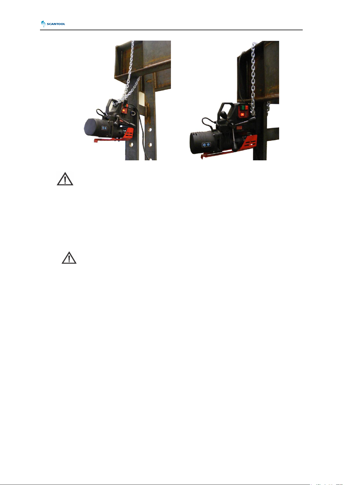
7. Machine is not secured with safety chain as a protection from falling down especially when
used at heights or in vertical or upside-down positions.
8. Bystanders are present in the immediate vicinity of machine.
Warning!
Read and save all instruction for future reference!
Important rules of safe use drilling machine on
electromagnetic base
1. Before attempting to work with the machine check the condition of electrical installation
including power cord and plug.
2. The drilling machine should be connected to an installation equipped with protection circuit
(grounding) and protected with a 16 A fuse for 220 V and 32 A fuse for 120 V. When used on
building sites, it must be supplied through a separation transformer made in the
second class of protection
3. Machine can be used outdoors, but is not weatherproof. Do not expose to rain, snow or frost.
4. Machine should not be used on: rusty surfaces, steel plates with thick covered with paint,
uneven surfaces, next to a welding machine.
5. In all cases always use a safety chain/strap (see Drawing No 1). The safety chain must not be
loose! To avoid this situation the safety chain should be wrapped around the element it is
hooked to.

COMPACT 75
COMPACT 75 Operator’s manual for drilling machine
- 7 -
It is recommended to use the safety chain following the pictures
6. Do not use the machine in explosion hazard zones.
7. Do not start to work if the machine has excessive play on guide slides.
8. Always wear safety goggles and ear protection.
9. Do not remove metal chips with bare hands.
10. Do not touch the spindle and the cutter during work.
Do not touch or replace the tool with power source on – while
electromagnetic base is being used.
11. Tools must be fastened firmly. When a milling cutter is used, check before start of work if tool
holding screws are screwed tight.
12. It is not permitted to use blunt of damaged tools.
13. Do not use milling cutter without pilots, and arbors without ejection spring.
14. Use only tools recommended in Operator’s Manual.
15. After use always clean drilling machine from metal chips and coolant.
16. Always unplug machine from power supply during any work on the machine.
17. Before each use the machine should be checked for the presence of damage and the proper
and consistent use. Check whether any of the parts are broken and all the parts are fasten
properly. Make sure to maintain proper conditions affecting work of the machine.
18. In the case that the machine falls on a hard surface, from a height, is wet or is subjected to
other unfortunate events that could affect its technical state – work should be terminated
immediately and the machine should be sent to service for inspection as soon as possible.
Drawing No 1 The safety chain application

COMPACT 75
COMPACT 75 Operator’s manual for drilling machine
- 8 -
It is not allowed to use drill on steel thinner than 10mm (3/8”). On thin
steel less than 10mm (3/8”) magnet’s adhesive power would be significantly
reduced what can cause machines failure or individuals injury. The machine
should be located on the work piece with the entire surface of the
electromagnetic base! It is recommended that each time, before positioning the
machine surface under the electromagnetic base should be sanded down with
abrasive paper!
Thickness lower than 5 mm: Magnetic Drilling Machine COMPACT 75 will
not start because of CLAMPING FORCE CONTROL SYSTEM.
Warning!
Read and save all instruction for future reference!

COMPACT 75
COMPACT 75 Operator’s manual for drilling machine
- 9 -
5. OPERATING INSTRUCTIONS
The drilling machine has a spindle with Morse Taper MT3 to use twist drill (by using the
reduction adapter if necessary) and annular cutters. Arbor mark AMT is mounted in spindle conical
taper to fix annular cutters.
Milling cutter (2) is located inside arbor body (1) and is fastened with screws (3). While fastening the
cutter in the socket, be aware that screws should be screwed tight so that they could not come
unscrewed. It is important to position the cutter in relation to the socket in such a way that fixing flats
on the cutter shank are positioned opposite to the fixing screws (3). Both fastening screws (3) should
be used to fasten the cutter. Pilot (5) is located inside the cutter. It makes it easier to position milling
cutter over centre of a planned hole. During drilling as the cutter goes deep into steel, the pilot moves
back into the arbor body and tightens discharge spring (4). That spring ejects slug which is a by-
product of milling a hole with a centre free cutter (Drawing No. 3).
Drawing No 3
Types of holes that can be done with a milling cutter
.
Drawing No 2.
Principle of milling cutter’s work

COMPACT 75
COMPACT 75 Operator’s manual for drilling machine
- 10 -
6. INSTALLING AND UNINSTALLING THE ARBOR
The arbor installation and uninstallation should be carried out when the
machine is turned off and disconnected from the power grid!
Installing the arbor:
1. Raise the guard (2) to the maximum.
2. Clean the inside of the spindle using a cotton cloth.
3. Before mounting, clean off the lubricant from the new arbor (3).
4. Place the arbor with the fin on top, and place it in the spindle.
5. By turning the arbor, align the fin to the appropriate slot in the spindle.
6. Using a light impact from the bottom side, drive the arbor into the spindle.
Uninstalling the arbor:
1. Raise the guard; turn the spindle so that the wedge MT opening in the spindle (1) is lined up
with the wedge MT opening in the reducer body.
2. Place the wedge MT (included as standard equipment) into the uncovered spindle opening
(1).
3. Hold down the arbor (3) with one hand.
4. Strike the wedge MT with a hammer, taking care to not to damage the arbor.
5. Carefully remove the arbor from the socket in the spindle.
6. Remove the wedge MT.

COMPACT 75
COMPACT 75 Operator’s manual for drilling machine
- 11 -
7. INSTALLING AND UNINSTALLING THE MILLING CUTTER
Milling cutter installation and uninstallation should be carried out when
the machine is turned off and disconnected from the power grid!
Installing the milling cutter:
1. Raise the drive and the slide (2) up using the lever (3);
2. Raise the guard (1) to the maximum in order to attain access to the arbor (4) screws (5);
3. Insert the appropriate type of pilot (6) into the milling cutter (7);
4. Position the milling cutter (7) with the cutter facing up, so that the flat sides of the milling cutter
are found facing the screws (5);
5. Put the milling cutter (7) into the arbor socket (4);
6. Tighten the screws securely (5).
Uninstalling the milling cutter:
1. Raise the drive and the slide (2) up using the lever (3);
2. Raise the guard (1) to the maximum in order to attain access to the arbor (4) screws (5);
3. Loosen the screws (5);
4. Remove the milling cutter (7) and the pilot (6) from the arbor socket (4).

COMPACT 75
COMPACT 75 Operator’s manual for drilling machine
- 12 -
8. MAGNETIC DRILLING MACHINE START UP
The machine is supplied in a metal box with complete standard equipment.
Before first drill:
•Steel elements of the drilling machine are protected for transit and storing with grease film. Before
first start up of the machine all grease should be removed. This especially applies to Morse Taper.
•Before each use all handles should be screwed into pinion.
Before setting the machine on an item make sure that:
•Substrate is a steel and ferromagnetic (some of stainless steel or acid-proof or do not conduct the
magnetic flux);
•Thickness of work piece is at least 10 mm (3/8”);
•Surface of steel under the magnet is flat;
•Wipe, brush or sand down clean surface where you intended to place the drilling machine; so that
you remove rust, paint, dirt etc which would reduce adhesive power of the electromagnetic base.
Preparation the machine for drilling:
1.Set the drilling machine on the surface of the element which hole is to be drilled.
2.Accurately and securely attach the drill spindle in the nest (see 0).
3.Plug in the drilling machine accordance to the requirements (see 0).
4.Set the axis of the spindle exactly over the place of drilling (the tool is over the centre of the hole).
5.Turn the magnetic base ON.
Prior to use!
Always make sure that the electromagnetic machine is secured from falling
down during vertical, ceiling work with original chain.

COMPACT 75
COMPACT 75 Operator’s manual for drilling machine
- 13 -
Preparation for cutting
1. Place the drilling machine on the working surface.
2. Secure the milling cutter firmly and accurately in the spindle socket
3. Fill the bottle of the cooling system with the cutting fluid.
4. For drill and milling cutter cooling during drilling it is recommended to use cutting fluids available
on the market in the condensed form. It is also possible to use emulsion formed by mixing water
and drilling oil.
Using pure water as a cutting fluid is not allowed.
5. Check operation of the cooling system. To do this loosen bottle nut, set the knob of the small valve
to position ”ON” to initially bend the pilot placed inside the milling cutter by lowering the drive on its
guides. The fluid will fill the system and after short period it will start flowing out from the inside of
the drill.
CAUTION: Cooling system works according to gravitation. Due to
this in another drilling position than vertical the cooling liquid must be
provided manually.
6. Define the direction of the spindle rotation.
7. Set proper rotational speed according to the type of the tool and working material.
8. Connect the drilling machine to electric network according to
9. Set the axis of the spindle right above drilling point (in the case of milling cutter the end of the pilot
helps with alignment).
10. Turn the mounting of the electromagnetic base on.
To be sure check if electromagnetic base is properly secured, in the case of horizontal
works, works on ceilings and on heights secure it by using chain or safety belt.
Preparation for tapping
1. Using a MT3 wedge (included in a set) put the milling head holder (AMT3-U-19/3-3, included in
the set) out of the drilling machine spindle.
2. Mount the tap socket with 1- or 2-axis compensation into the spindle (not included in the set).
3. Choose the right socket adapter to match tipping diameter. Mount tap no. 1 into the adapter and
place it in the compensation socket.
4. In the case of using taps with conical handle, mount it directly into the spindle or by using reducer
with MT3 cone.

COMPACT 75
COMPACT 75 Operator’s manual for drilling machine
- 14 -
Types of a ground material
As shown on the graphs (Drawing 4) magnetic clamping force of the electromagnetic base to the
ferromagnetic ground depends on its magnetic properties. Steel with increased carbon content and
some other alloying ingredients has lower magnetic permeability, what causes a decrease in the
clamping force. Also a thickness of a work piece, on which the drill is placed, is significant.
Maximum clamping force of the electromagnetic base to a 5 mm thick work piece
surface is only about 25% of a clamping force obtained from a smooth, plane, and 22
mm thick standard plate.
If such thin ground material does not bow, one can try to carry out drilling of a
hole, although with keeping the strictest precautions. Particularly a magnitude of a
pushing force on a feed handle should be very limited.
Appropriate rpm should be adjusted depending on if drilling would be carried out with a drill bit, or
with trepan type metal cutter and a metal cutter’s diameter. A drive is equipped in mechanical 2-step
reducing gearbox of a motor rpm. A general dependence between drilling diameter and drilling speed
is shown in graphs (drawing 5), detailed guide is supplied by manufacturer of used drilling tools. The
graph is just a general guide and the shown dependence applies to average structural steel.
Cooling agent is fed gravitationally from a coolant bottle through an arbor to an inside of the metal
cutter. For on-a-wall and on-a-ceiling positions special cooling pastes have to be used.

COMPACT 75
COMPACT 75 Operator’s manual for drilling machine
- 15 -
Drawing 4. Clamping force depending on the thickness of the substrate and the value gap.

COMPACT 75
COMPACT 75 Operator’s manual for drilling machine
- 16 -
Electromagnetic base clamping force control system
This system for security reasons is an integral part of each drill type PRO. It works by constant
monitoring of the electromagnetic force base adhesion value to the substrate. In the case of fall the
force value below to guarantee safe operation of the machine, the system automatically switches off
the drive drill. It also does not allow enabling drive which does not guarantee the proper clamping
force.
Clamping force depends on: type and thickness of substrate, thick coatings on the substrate, rust
or other contaminants, lack of flatness of the substrate, excessive roughness of the surface, and
excessive wear of the lower part of the electromagnetic base.
If there is a problem to enable drive after turn on of the electromagnetic base so drive works only
after START button is pressed, and after release the drive is off – it means that system works
properly. The system didn’t allow to for further work due to insufficient clamping force drills.
Working in difficult areas
While working in difficult access areas as well as left-handed operator, there’s a possibility to
change location of the pinion with spoke handles to the other side of drilling machine.
Additional option of machine COMPACT 75
Drilling machine COMPACT 75 is equipped with additional special function which enable to move
upper part of machine about 15 degrees and 15 mm front/back using allen key s=10, without moving
the electromagnetic base.
Drawing No 6.
Parameter of set-up magnetic base

COMPACT 75
COMPACT 75 Operator’s manual for drilling machine
- 17 -
Installing and uninstalling the cooling system
Installing the cooling system:
a) Place the machine in the vertical position,
b) Slide the drive and the slider (1) up using lever (2),
c) Coolant bracket (7) with cooling unit (6) on screws (8) located to the side of the slider,
d) Connect the cooling conduit ending (3) with the coolant coupling (4) found in the cooling ring (5).
Before starting the machine:
•Remove the bottle’s cap,
•Fill it with cooling lubricant,
•Replace bottle cap.
After fulfilling the above actions and making sure that the system has been appropriately fixed, and the
cooling conduit (2) is placed correctly on the coolant coupling (4), the bottle cap should be loosened
by 1/3 of a turn in order to deaereate it, turn on the valve (3), so that liquid travels to the hose, after
which the machine can be started.
After ending work, one must remember to tighten the bottle cap and turn off the valve (9) (to
prevent liquid from leaking during the time that the machine is not being used) and uninstall the
cooling system (6) before placing the machine in the box.
Uninstalling the cooling system:
a) Place the machine in the vertical position.
b) Slide the drive and the slider (1) up using lever (2).
c) Disconnect the cooling conduit ending (3) and the coolant coupling (4) found in the cooling ring
(5).
d) Take off the cooling system.

COMPACT 75
COMPACT 75 Operator’s manual for drilling machine
- 18 -
Parameters depending on spindle speed (drilling)
Due to the distribution of lubricant after every days work position of gear lever (used for selection of
gearbox speed) should be changed. For example if machine worked with 160 rpm speed, it should be
switched to 420 rpm.
Relationship between machine speed and cutter diameter:
Relationship between machine speed and twist drill diameter:
The twist drill diameter Rotary Speed
[rpm]
[inch] [mm]
0,70÷1,25 18÷32 80÷160
0,30÷0,70
8÷17
210÷420
The cutter diameter Rotary speed
[rpm]
[inch] [mm]
1,38÷3,00 35÷75 80÷160
0,50÷1,37
12÷34
210÷420

COMPACT 75
COMPACT 75 Operator’s manual for drilling machine
- 19 -

COMPACT 75
COMPACT 75 Operator’s manual for drilling machine
- 20 -
Cutting
1. Clean the surface which the machine will be mounted to.
2. Place and secure the machine, press the switch of the MAGNET base to position “I”.
3. Before mechanically starting the engine choose proper rotational speed range (dependent
on the performed hole) using changing gear lever in the reducer (Drawing 7).
4. Choose the direction of the spindle rotation changing switch, by setting it to position “P” or
“L”.
CAUTION! Choosing inappropriate direction may cause the damage of the motor..
5. Start the drilling machine by pressing green MOTOR (02) button with „I” indication.
6. By turning levers bring the tool close to working surface slowly and start drilling with care.
Penetration of the tool into the working material should be performed accurately.
7. When drilling with the milling cutter it is required to make the hole with just one pass,
without retracting the tool. It will ease pushing out the core from the inside of the milling
cutter.
CAUTION: When the milling cutter goes through the material, the core is pushed
out from the inside with quite significant force.
8. For the safety do not allow neither to create too long metal chips nor to roll them on the
holder or the milling cutter.
9. Use knob (03) to set rotational speed respective to milling conditions.
10. After the hole is made the tool should be retracted from the working piece.
11. To stop the drive, push red ”O” START-STOP button (01). In such case the drilling
machine driver is turned off, while the electromagnetic base is still turned on.
12. Turn the electromagnetic base off – press the MAGNET button to position ”O”. Remove
formed metal chips.
13. After finishing work disconnect the drilling machine power cord from the socket, clean the
machine and the tool from metal chips and remainder coolant.
14. Before putting the drilling machine into the tool box, remove milling cutter from the holder.
(03) (02)
(05) (01)
Drawing. 6. Control Panel
Drawing. 7. View of the machine
Table of contents
Other Scantool Drill manuals
Popular Drill manuals by other brands

HOLZMANN MASCHINEN
HOLZMANN MASCHINEN LBM 250C user manual

Skil
Skil 6389 Original instructions

Hitachi
Hitachi B 16RM Instruction manual and safety instructions

Milwaukee
Milwaukee M18 CPD Original instructions

Truper
Truper ROTO-1/2A8-2 manual

Chicago Electric
Chicago Electric 67616 Owner's manual and safety instructions