Sceptre SC7M41 User manual

1
User’s
Users' Manual
Chapter1:Overview..............................3
<1.1 Introduction.....................................................3
<1.2 Layout Diagram...............................................3
<1.3 Specification.....................................................4
<1.4 Check the Package...........................................6
Chapter 2:Jumpers & Connectors.....7
<2.1 Jumpers’ Sites..................................................7
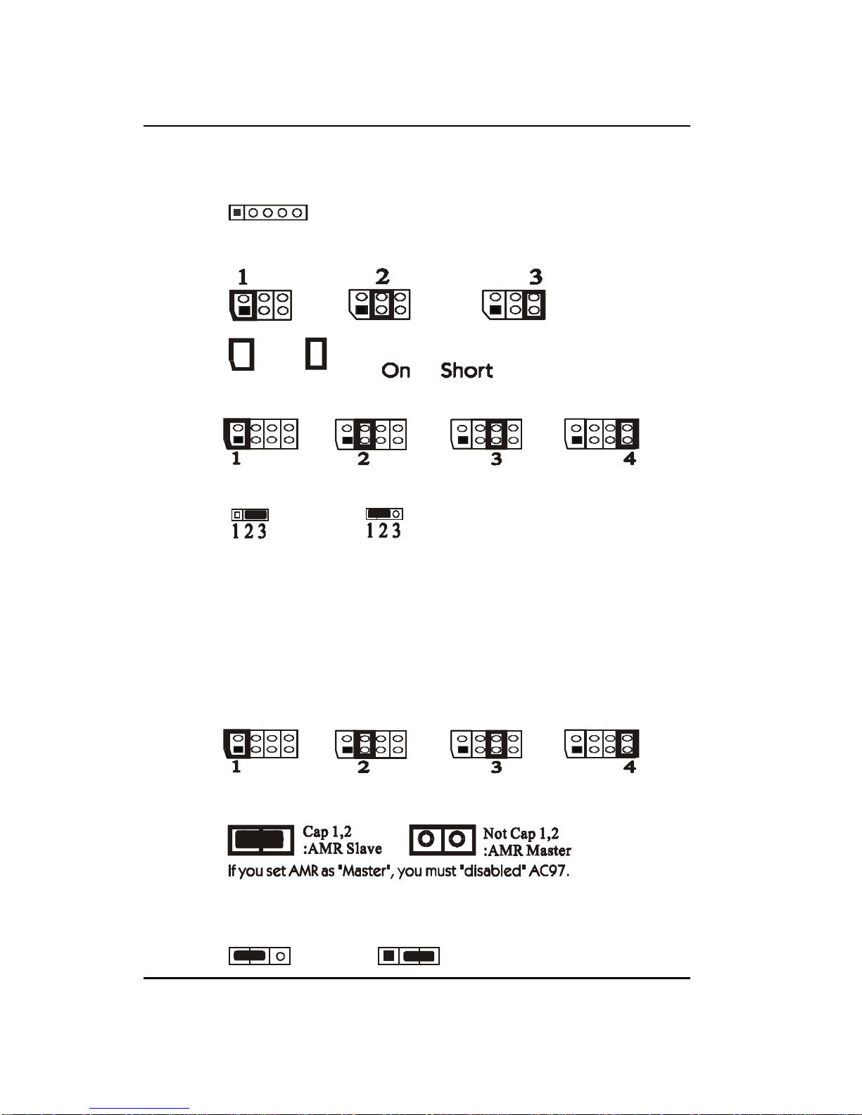
<2.2 Jumpers’ Setting..............................................8
<2.3 Jumpers’ Setting Menu....................................9
<2.4 CPU Suggested..............................................11
<2.5 Connectors......................................................12
Chapter 3:BIOS .................................15
<3.1 CMOS Setup Utility......................................15
<3.2 Standard CMOS SETUP................................16
<3.3 BIOS FEATURES SETUP.............................17
<3.4 Chipset Features Setup...................................19
<3.5 Power Management Setup..............................21
<3.6 PnP/PCI Configuration..................................23
<3.7 Load BIOS Defaults......................................24

2
User’s
<3.8 Load SETUP Defaults....................................24
<3.9 CPU SPEED SETTING.................................25
<3.10 Integrated Peripherals..................................26
<3.11 Supervisor/User Password...........................28
<3.12 IDE HDD AUTO DETECTION..................30
<3.13 Save & Exit Setup.......................................30
<3.14 Exit Without Saving....................................30
Chapter 4 :Trouble-Shooting ............31
<4.1 Sceptre’s Website.............................................31
<4.2 Update BIOS..................................................31

3
User’s
1
Chapter1:Overview
1.1 Introduction
1.2 Layout Diagram
We illustrate it by the following diagram.
This Motherboard adopts VIA Apollo MVP4 (66/100) Chipset with
Codec and AMR (Audio Modem Riser)...etc. Besides this, it can also
support a series of Socket 7 Types’ CPUs and perform well on various
working platforms.

4
User’s
1.3 Specification
BB
BB
BCPU:
All Socket 7 Processors (Host Bus up to 100 MHz)
BB
BB
BChipset:
VIA Apollo MVP4 (VT8501+ VT82C686A) (66/100)
BB
BB
BBIOS:
AWARD BIOS with DMI, Green Fun., PnP, and Anti-virus.
Support LS 120/ZIP/CD ROM Booting
2MB Flash Memory
BB
BB
BPower Supplier
ATX Power Supplier
BB
BB
BPCB Size
245mm X 210mm Micro ATX Size
BB
BB
BSwitching Voltage Regulator
Support 2.0V to 3.5V Switch
BB
BB
BSystem Memory
2X 168-Pin DIMM Socket with 3.3V SDRAM
Total from 8MB to 512MB
BB
BB
BOnboard Memory
CPU Built-in Memory
L1 Cache :Depends on CPU’s Type
L2 Cache : 512KB
BB
BB
BOnboard Input/Output
Onboard 3D AGP VGA
Onboard Sound
2 XUSB Ports Support
2 XPCI Bus Master IDE Ports

5
User’s
(Support up to 4 IDE devices and LS-120 MB Floppy Drive):
(1)PIO Mode 3 and 4
(2)DMA Mode 2
(3)Ultra DMA 33/66
Standard IrDA Support
PS/2 Mouse and Keyboard Support
1 Floppy Port (Up to 2.88MB ; 3 Mode Floppy Supported)
2 Serial Ports (16550 Fast UART Compatible)
1 Parallel Port (ECP, EPP Port)
BB
BB
BExpansion Slot:
1 XISA,3 XPCI and 1 XAMR
BB
BB
BPower Management:
Advanced Configuration Power Interface (ACPI) Stnadard
ready for PC’98
Back up Battery CR-2032
Power On by RTC Alarm, Modem Ring, LAN & Soft-Power
Switch (for ATX Power Only)
Power Off by Windows 95 & 98 Shut Down & Soft Power
Switch (for ATX Power Only).
BB
BB
BMonitoring Function:
Vital Voltages on the Power Supply
CPU Temperature, CMOS Battery Voltage ,FAN Activity
BB
BB
BOthers:
FCC DoC (Normal: 47 CFR 15.31),CE Marking
Surrounding Temperature(On Working):0~50 oC
Relative Humidity:0~85 %

6
User’s
1.4 Check the Package
Enclosed in our package are:
Motherboard
User’s Manual
Floppy Cable, COM 2 Cable & ATA-66 Cable
CD-ROM Disc with Driver

7
User’s
Chapter 2:Jumpers & Connectors
2.1 Jumpers’ Sites
There are several Jumpers on our motherboard. They are illus-
trated by (A),(B),(C),(D),(E),(F) and (G).
1
(A)
(B)
(C)
(E)
(F)
(G)
(D)

8
User’s
2.2 Jumpers’ Setting
BB
BB
B(A) :JIR1 ÎÎ
ÎÎ
ÎIrDA Connector
BB
BB
B(B) :JP 1 ÎÎ
ÎÎ
ÎCPU Ratio’s Setting
2 3 1 2
1 3
BB
BB
B(C) :JP 2 ÎÎ
ÎÎ
ÎCPU Frequency’s Setting
1 2 1 2 341 3 4
2 3 4
BB
BB
B(F) :JP 5 ÎÎ
ÎÎ
ÎAMR Slot’s Slave / Master Setting
BB
BB
B(G) :JP 6 ÎÎ
ÎÎ
ÎOnboard Codec AC’97
Cap 1,2:
Enabled Cap 2,3:
Disabled
1 2 3 1 2 3
The steps to Clear CMOS are:
(1)Turn off the system’s power.
(2)Detach the cap from Pin 1 and Pin 2
(3)Cover the cap on Pin 2 and Pin 3.
(4)After a while, place the cap on Pin 1 and Pin 2.
BB
BB
B(E) : JP 4 ÎÎ
ÎÎ
ÎVcore’s Setting
1 2 1 2 341 3 4
2 3 4
BB
BB
B(D) :JP 3 ÎÎ
ÎÎ
ÎClear CMOS
Or Represents Cap this Pin Set
(i.e. or )

9
User’s
2.3 Jumpers’ Setting Menu
BB
BB
BJP 1 (CPU Ratio’s Setting) : OnÎÎ
ÎÎ
ÎCap this Pin Set
PinNo.
CPU’s Ratio 123
1.5 Off Off Off
2.0 On Off Off
2.5 On On Off
3.0 Off On Off
3.5 Off Off Off
4.0 On Off On
4.5 On On On
5.0 Off On On
5.5 Off Off On
BB
BB
BJP 2 (CPU FREQ.’s Setting) :OnÎÎ
ÎÎ
ÎCap this Pin Set
Suggested Settings
CPU’s
FREQ.
(MHz)
PinNo.
1234
CPU
Ratio PCI’s
FREQ.
(MHz)
60 Off Off Off Off X230
66.8 On Off Off Off X2 33.4
70 Off On Off Off X235
80 Off Off On Off X326.67
83.3 On Off On Off X3 27.76
90 On On Off Off X325
95.25 Off On On Off X3 31.75

10
User’s
BB
BB
BJP 4 (Vcore’s Voltage) :OnÎÎ
ÎÎ
ÎCap this Pin Set
PinNo.
Voltage 1 234
2.1 V On Off Off Off
2.2 Off On Off Off
2.3 On On Off Off
2.4 Off Off On Off
2.5 On Off On Off
2.6 Off On On Off
2.7 On OnOnOff
2.8 Off Off Off On
2.9 On Off Off On
3.0 Off On Off On
3.1 On On Off On
3.2 Off Off On On
3.3 On Off On On
3.4 Off On On On
3.5 On OnOnOn
Not Suggested Settings (Overclocking)
CPU’s
FREQ.
(MHz)
PinNo.
1234
CPU’s
Ratio PCI’s
FREQ.
(MHz)
75 Off Off Off Off X2 37.5
80 On Off Off On X240
83.3 Off On Off On X2 41.65
100 On On On Off X3 33.33
105 On On Off On X3 35
110 Off Off On On X3 36.67
115 On Off On On X3 38.33
120 Off On On On X340
124 On On On On X3 41.33

11
User’s
2.4 CPU Suggested
.
CPU’s Specification CPU FREQ. (MHz) Ratio Bus FREQ. (MHz)
AMDK6 II/III 550 550 5.5 100
AMDK6 II/III 500 500 5.0 100
AMDK6 III/450 450 4.5 100
AMDK6 III/400 400 4.0 100
AMDK6 2/475 475 5.0 95
AMDK6 2/450 450 4.5 100
AMDK6 2/400 400 4.0 100
AMDK6 2/380 380 4.0 95
AMDK6 2/366 366 5.5 66
AMDK6 2/350 350 3.5 100
AMDK6 2/333 333 3.5 95
AMDK6 2/300 300 3.0 100
AMDK6 2/266 266 4.0 66
AMDK6/300 300 4.5 66
AMDK6/266 266 4.0 66
AMDK6/233 233 3.5 66
AMDK6/200 200 3.0 66
AMDK6/166 166 2.5 66
AMDK5/133 100 1.5 66
AMDK5/100 100 1.5 66
Intel PentiumP54C 166 2.5 66
Intel PentiumP54C 133 2.0 66
Intel PentiumP54C 100 1.5 66
Intel PentiumP55C 233 3.5 66
Intel PentiumP55C 200 3.0 66
Intel PentiumP55C 166 2.5 66
IBM/ Cyrix MII PR 333 333 3.0 83
IBM/ Cyrix MII PR 300 300 3.0 75
IBM/ Cyrix MII PR 300 300 3.5 66
IBM/ Cyrix 6X86MX-PR233 200 3.0 66
IBM/ Cyrix 6X86MX-PR200 166 2.5 66
IBM/Cyrix6X86-PR166+* 133 2.0 66
IBM/Cyrix6X86L-PR166+* 133 2.0 66

12
User’s
1
2.5 Connectors
BB
BB
BConnectors’ Sites
We mark these connectors’ sites by Arabic Number.
BB
BB
B1:FDD
FDD is used to connect with Floppy disk.
BB
BB
B2:ATX PWR
ATX PWR is used to connect with ATX Power Supply.
BB
BB
B3:DIMM 1,DIMM 2 & DIMM 3
They are used to hold SDRAM.
BB
BB
B4:IDE 1 & IDE 2
IDE 1 and IDE 2 are used for Hard Disk Driver.
BB
BB
B5:J 2

13
User’s
J2
PWLED(Power LED) is used to imply the Power’s status.
When your system hang on,use RESET to reboot.
Use PW-ON button to get your system running.
HDLED is used to imply HDD’s status.
SPEAKER is used to connect the speaker to the motherboard.
BB
BB
B6:JFAN2
It is used to disperse System’s heat.
BB
BB
B7: ISA
ISA is used to hold ISA Card.
BB
BB
B8:PCI 1, PCI 2 & PCI 3
PCI 1/2/3 are used to hold PCI Card.
BB
BB
B9:JCD IN1
JCD IN1 is for CD ROM Machine of Japanese Specification.
BB
BB
B10:CD IN1
CD IN1 is for CD IN1 is for non-Japanese CD ROM Machine.
BB
BB
B11:JWOL1
JWOL1 is for Wake On LAN function.
BB
BB
B12:AMR1
It is used to hold AMR Card.
BB
BB
B13:Line Out, Line In, Microphone & Game Port
Line Out is for voice’s output.
Line In is for voice’s input.
Microphone is for recording.
Game Port is for Joystick.

14
User’s
BB
BB
B15:COM1
It is used to connect with related device.
BB
BB
B16:Printer
It is used to connect with Printer.
BB
BB
B17:USB
It is used to connect with USB device.
BB
BB
B18:PS2 KB
PS2 KB is for PS2 specification’s keyboard.
BB
BB
B19:MS
MS is for Mouse to plug in.
BB
BB
B20:JFAN1
JFAN1 is used to disperse CPU’s heat.
BB
BB
B21:COM2
COM2 is for outer related device.
BB
BB
B22:Socket 7
Socket 7 is used to hold Socket7 Series CPUs.
BB
BB
B14:VGA1
It is used to connect with related device.
Other manuals for SC7M41
1
Table of contents
Other Sceptre Motherboard manuals