Schaltbau CT1115/04 User manual

33
ContactorsContactors
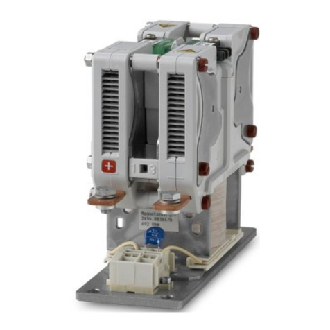
CT1115/04 – CT1115/08 – CT1115/10/11
CT1130/04 – CT1130/08 – CT1130/10/11
CT1215/04 – CT1215/08 – CT1215/10/11
CT1230/04 – CT1230/08 – CT1230/10/11
Single pole / double pole NO
power contactors for AC and DC
Installation and
maintenance instructions
Manual C20-C21-M.en

22019-03-06 / V1.0
Contactors CT/CU Series – Installation and Maintenance Instructions
Content
1. Important basic information ......................................................................................... 4
1.1 Legal notes .............................................................................................................................. 4
1.2 Conventions for this manual............................................................................................. 4
2. General and security information ................................................................................ 4
2.1 Observing the instructions................................................................................................ 4
2.2 User obligations..................................................................................................................... 5
2.3 Intended use........................................................................................................................... 5
2.4 Ambient conditions.............................................................................................................. 5
3. Dangers and security measures.................................................................................... 6
3.1 Electrical dangers.................................................................................................................. 6
3.2 Other dangers ........................................................................................................................ 7
3.3 Measures for avoiding damages and malfunctions ................................................. 8
4. Introduction...................................................................................................................... 9
4.1 CT/CU Power contactors for AC and DC ....................................................................... 9
4.2 Features .................................................................................................................................... 9
4.3 Applications ............................................................................................................................ 9
4.4 Technical information and material specication..................................................... 9
5. Description......................................................................................................................10
5.1 Survey of the CT/CU series (stock items)....................................................................10
5.2 Parts description..................................................................................................................13
Single pole contactors.......................................................................................................13
Double pole contactors ....................................................................................................13
5.3 Switching diagram..............................................................................................................14
6. Storage.............................................................................................................................15
7. Unpacking and handling..............................................................................................15
7.1 Unpack the device ..............................................................................................................15
7.2 Check parts for transport damage................................................................................15
8. Correct mounting positions.........................................................................................16
9. Installation ......................................................................................................................17
9.1 Dimensions/interfaces to the vehicle..........................................................................17
9.2 Mechanical installation.....................................................................................................17
Preliminaries .........................................................................................................................17
Safety.......................................................................................................................................17
Required tools and auxiliaries ........................................................................................17
Mounting holes....................................................................................................................18
Mechanical installation procedure ...............................................................................19
9.3 Electrical Installation..........................................................................................................20
Preliminaries .........................................................................................................................20
Safety.......................................................................................................................................22
Required tools and auxiliaries ........................................................................................22
Electrical installation procedure....................................................................................23
9.4 Checks .....................................................................................................................................30
Document Revision History
Date Rev. Level Description Pages
2019-03-06 1.0 First release all

3
2019-03-06 / V1.0 Contactors CT/CU Series – Installation and Maintenance Instructions
10. Maintenance...................................................................................................................31
10.1 Safety.......................................................................................................................................31
10.2 Preventive maintenance...................................................................................................31
Intervals for regular checks..............................................................................................31
Regular check activities ....................................................................................................32
10.3 Corrective maintenance ...................................................................................................33
Replace the main contacts and the ceramic protection insert...........................33
Checks .....................................................................................................................................40
Replace the auxiliary switches........................................................................................41
Checks .....................................................................................................................................44
11. Spare Parts ......................................................................................................................45
11.1 Single pole contactors.......................................................................................................45
11.2 Double pole contactors ....................................................................................................45
12. Technical Data ................................................................................................................46
13. Disposal ...........................................................................................................................46

42019-03-06 / V1.0
Important basic information
Contactors CT/CU Series – Installation and Maintenance Instructions
1. Important basic information
1.1 Legal notes
Without prior written consent of Schaltbau GmbH, this
manual is not allowed to be electronically or mechani-
cally reproduced – as a whole or in parts – be distrib-
uted, changed, transmitted, translated into another
language or used in any other way.
Schaltbau GmbH cannot be held liable for damage
caused by not observing (or only partly observing) the
manual.
1.2 Conventions for this manual
This manual describes the installation, commisioning
and maintenance of the contactors.
Cross references are presented in bold italics.
To highlight particularly important safety instructions
and other information, the following symbols are used
in this instructions:
DANGER
Indicates a hazardous situation with a high level
of risk which, if not avoided, will result in death or
serious injury.
WARNING
Indicates a hazardous situation with a medium level
of risk which, if not avoided, could result in death or
serious injury.
CAUTION
Indicates a hazardous situation with a low level of
risk which, if not avoided, may result in minor or
moderate injury.
NOTICE
Indicates a hazardous situation which, if not avoided,
may result in property damage, such as service inter-
ruption or damage to equipment or other materials.
Refers to technical features and methods
aimed at facilitating work or to particu-
larly important information.
This manual refers to single pole and double pole con-
tactors of the types:
Single pole
contactors
CT/CU 1115/04
CT/CU 1115/08
CT/CU 1115/10/11
CT/CU 1130/04
CT/CU 1130/08
CT/CU 1130/10/11
Double
pole con-
tactors
CT/CU 1215/04
CT/CU 1215/08
CT/CU 1215/10/11
CT/CU 1230/04
CT/CU 1230/08
CT/CU1230/10/11
X
CT contactors are devices for bidirectional DC or AC
operation and have electromagnetic blowout coils.
X
CU contactors are devices that only work in uni-
directional DC operation. CU contactors have per-
manent magnets instead of blowout coils.
X
The contactor types 1115/10, 1215/10 are UL rec-
ognized components (Underwriters Laboratories).
X
The contactor types CT XXXX/10 and CT XXXX/11
as well as CU XXXX/10 and CU XXXX/11 have basi-
cally the same structure. Apart from electrical data
the only dierence are the heat sinks:
-CT/CU XXXX/11 contactors have heat sinks
-CT/CU XXXX/10 contactors do not have heat
sinks
2. General and security information
The contactors dealt with in this document are intend-
ed for use with high-voltage systems for special instal-
lations. They are designed and tested in compliance
with the generally recognised state of the art. However,
improper use, operation, handling, maintenance of or
tampering with electric equipment can cause serious
or fatal injury to the user or others, and the appliance or
other property can be damaged.
The operation, maintenance and installation instruc-
tions for the contactors must therefore be strictly fol-
lowed.
Any uncertainties must be claried and all queries must
include details of the type of device and the serial num-
ber.
Only authorized and trained personnel are allowed to
plan and carry out all mechanical and electrical installa-
tions, transport, commissioning, as well as maintenance
and repair work. This applies to the observation of the
general installation and safety regulations for high-volt-
age systems as well as the proper use of tools approved
for this purpose. Electric equipment requires protection
from moisture and dust during installation and storage.
2.1 Observing the instructions
X
All sta must read and understand the instructions
in this manual and adhere to them when working
with the device.

5
2019-03-06 / V1.0 Contactors CT/CU Series – Installation and Maintenance Instructions
General and security information
X
Always carefully observe all safety warnings!
2.2 User obligations
X
Observe all applicable national provisions, all safe-
ty, accident prevention and environmental regula-
tions as well as the recognized technical rules for
safe and proper working.
X
Carry out regular inspections of all protection and
safety devices to see if they work properly.
X
Work on electric equipment may only be per-
formed by an expert or trained personnel working
under the direction and supervision of an expert
according to the applicable rules of electrical en-
gineering.
X
An expert is a person who can judge and recog-
nise the possible dangers of the jobs commended
to him based on his training, knowledge and ex-
perience and by knowledge of the appropriate
regulations.
X
Work on the contactors must only be carried out
by sta who meets the requirements set out in this
manual.
X
Sta must be informed clearly about who is re-
sponsible for the maintenance of the contactors.
X
After each installation work and after replacement
of main contacts, contact bridge or after any other
modications, alterations or maintenance works,
always perform complete checks according to
these standards:
-IEC 60077-2
-IEC 60947-4-1
2.3 Intended use
X
The contactors have been designed and tested ac-
cording to national and international standards.
Due to their unique features they can also be used
in a variety of applications.
X
The contactors must only be used under operating
conditions according to the technical specication
and the instructions in this manual.
X
None of the operating conditions dened in our
catalogues C20.en and C21.en in section “Speci-
cations“, such as voltages, currents, ambient con-
ditions, etc. may be changed.
X
The contactors must only be used when all protec-
tive devices are present, have been installed prop-
erly and are fully operational.
X
The contactors must not be contaminated with
aggressive media.
X
Contactors may not be used without further pro-
tective measures in potentially explosive atmos-
pheres.
X
The switching device meets the requirements
of basic insulation. Make sure the frame or plate
onto which the drive of the contactor is mounted
is earthed in a shock and vibration resistant way.
X
Do not use the contactor without properly mount-
ed arc chute.
X
The contactor has unprotected live parts and car-
ries labels that warn of the hazard. This caution
must be observed and the labels must not be re-
moved in any way.
X
The required clearance of live parts to earth and
other parts of the contactor is to be observed as
well as the safety regulations of the applicable
standards.
X
Switching at maximum breaking capacity might
require larger clearance! Do not hesitate to ask our
advice for dimensioning.
X
Do not use the contactor without protective cov-
ers (for coil terminals and auxiliary switches).
X
Coil suppression for reducing surges when the coil
is switched o is optimally attuned to the contac-
tor‘s switching behaviour. The existing opening
characteristic must not be negatively inuenced
by parallel connection with an external diode.
X
Improper handling of the contactors, e.g. when
hitting the oor with some impact, can result in
breakage, cracks and deformation. Always handle
the contactors with care.
X
Use the contactor only according to its intended
use. Replace or repair damaged parts exclusively
with original parts. Any other usage of or tamper-
ing with the contactors is considered contrary to
its intended use. No liability is assumed for damag-
es and accidents caused due to non-compliance
with the instructions in this manual or improper
use of the contactors.
2.4 Ambient conditions
NOTICE
The contactors are constructed for specic ambient
conditions.
X
Operate the contactors only according the
ambient conditions, like temperature ranges,
IP protection classes, degree of soiling, etc., as
dened in our catalogues C20.en and C21.en in
section “Specications“.
The catalogues are available under:
https://www.schaltbau.com/en/media-library/

62019-03-06 / V1.0
Dangers and security measures
Contactors CT/CU Series – Installation and Maintenance Instructions
3. Dangers and security measures
3.1 Electrical dangers
DANGER
The contactors are high voltage switches. The touching of electrically conducting parts may result
in serious injuries or even death!
Energized parts are all metal parts belonging directly to one of the circuits or wires leading there. All
other visible metal parts and wires may also be energized in the case of a failure.
Before beginning any work on the contactors, always observe the following safety regulations:
X
Disconnect on all sides
X
Ensure that it is not possible to reconnect unintentionally
X
Clearly mark your work area
X
Make sure that there is no voltage present
X
Earth and short circuit the installation; this also includes the discharging of any capacitors in
the main circuit
X
Besides the main electric circuit, also disconnect additional and auxiliary circuits
X
Cover or insulate adjacent energized parts
X
Only an electrically skilled person may determine if there is no voltage present
X
When the work has been concluded, proceed the other way round.
DANGER
The contactors are equipped with two protective caps for the coil terminal and auxiliary switches.
The protective caps are parts of the insulation system. Operation of the contactors without the pro-
tective cups may result in serious injuries or even death!
X
Never operate the contactors without the 2 protective caps.
X
When removing the protective caps during installation or maintenance works, make sure that
the protective caps are re-installed before the contactors are put into service.
DANGER
The contactors are equipped with a protective earth terminal. Without earth connection, metal
parts and wires may be energized in the case of a failure. Risk of serious injuries or even death!
X
Make sure that the contactors are connected to earth.
X
Make sure that the wire gauge of the earthing cables complies with the specic short circuit
conditions.
DANGER
In the case of a failure of the equipment;
X
don‘t use it anymore
X
immediately contact the manufacturer.

7
2019-03-06 / V1.0 Contactors CT/CU Series – Installation and Maintenance Instructions
Dangers and security measures
DANGER
Interventions in the equipment may cause serious impairments to the safety of men and construc-
tions. They are not permissible and lead to an exclusion of liability and warranty.
DANGER
All checks and the raplacement of components or groups of components may only be carried out by
qualied personnel according to the instructions of Schaltau. All spare parts must be parts delivered
by or released by Schaltbau..
3.2 Other dangers
WARNING
Exclusively use the contactors for purposes as indicated in the specications and data sheets.
A wrong application can cause accidents and severe damages to persons!
X
The manufacturer doesn‘t take the responsibility for accidents which were caused by improper
use of the product.
WARNING
The contactor is heavy. Risk of injury and damage to the device.
X
Take care when handling the contactor.
X
Always two persons should be available when unpacking and carrying the contactor.
X
When carrying the contactor always hold it on the base plate.
X
Do not carry the contactor by holding it at the upper module.
CAUTION
The contactors may grow warm during operation and they may become hot depending on the am-
bient temperature and the conditions of use. Risk of burns!
X
Before beginning any work on the contactors make sure that the heated components have
cooled down.
CAUTION
The contactors contain sharp-edged parts. Risk of injury!
X
Use appropriate tools for installation and maintenance works on the contactors.
X
Wear protective gloves when working with sharp-edged components.

82019-03-06 / V1.0
Dangers and security measures
Contactors CT/CU Series – Installation and Maintenance Instructions
3.3 Measures for avoiding damages and malfunctions
NOTICE
Aggressive uids may damage the contactors.
X
Make sure that the contactors are not exposed to aggressive uids.
NOTICE
Improper handling of the contactors, e.g. when hitting the oor with some impact, can result in breakage, cracks
and deformation.
X
Make sure that the contactors are always used properly.
X
Do not throw the contactors to the oor.
X
Regularly sight-check the contactors for potential damages.
X
Immediately replace damaged components.
NOTICE
The contactors contain strong (permanent) magnets. These magnets can attract ferromagnetic particles and
may damage the contactors.
X
Make sure that the contactors are installed at a location, where no ferromagnetic particles can be attracted..
NOTICE
The contactors contain strong (permanent) magnets. These magnets can destroy data on credit cards or similar
cards.
X
Keep credit cards or similar cards away from the contactors.
NOTICE
During the switching o, strong electromagnetic elds are generated in the surroundings of the contactors.
These may inuence other components close to the contactors.
X
Make sure that the contactors are installed at a location, where no other components can be aected.
NOTICE
In the case of damage, wear and tear and/or soiling of the contactor components - in the form of a partial break,
sharp edges and discoloured surfaces - the functional safety of the contactors is no longer guaranteed.
X
Carry out regular visual checks to detect wear and tear and dirt.
X
Immediately replace damaged parts.
X
Immediately remove dirt without leaving any residues.
X
Immediately replace parts with stubborn dirt.
NOTICE
Detent-edged rings and detent-edged washers have a limited life time. After 3 times opening of screws secured
with detent-edged rings or detent-edged washers, the rings or washers must be replaced by new ones.
X
Record the frequency of screw opening in the work log.
X
After 3 times opening of screws, replace detent-edged rings or detent-edged washers by new ones.

9
2019-03-06 / V1.0 Contactors CT/CU Series – Installation and Maintenance Instructions
Introduction
4. Introduction
4.1 CT/CU Power contactors for AC
and DC
With the CT/CU contactor series Schaltbau expands its
product line of state-of-the-art power contactors. The
outstanding technical feature is the innovative com-
bination of electromagnetic and permanent-magnetic
blowout technology for electric arc control. The suc-
cessful combination of these two principles greatly im-
proves both switching functionality and reliability and
forms a practical and economically impressive device
concept.
CT contactors are devices for bidirectional DC or AC op-
eration and have electromagnetic blowout coils.
CU contactors are devices that only work in unidirec-
tional DC operation. CU contactors have permanent
magnets instead of blowout coils.
The CT/CU contactor concept is exible and can be
adapted to suit the needs of the customer. Due to its
technical characteristics, its economical advantages, its
compactness and versatility, the CT/CU power contac-
tor series is simply predestined for use in industrial and
railway applications alike. The contactors are especially
suited for use in locomotives, cranes, and converters of
wind turbines and PV installations, but also in mining.
4.2 Features
X
Compact, rugged innovative design
X
2 voltage levels (1,5 kV, 3 kV)
X
Double-break contacts
X
1, 2, and 31pole versions
X
Easy inspection and replacement of main contact
tips
X
Easy to replace arc chute
X
Drive system with coil tolerance according to rail-
way standards
X
Functional insulation for main circuit
X
Basic insulation between main circuit and protec-
tive earth
X
Reinforced insulation between main circuit and
control circuit/auxiliary circuit
1Upon request
4.3 Applications
CT/CU Series contactors comprise a number of various
design versions catering to a wide range of uses, such
as:
X
Main contactor for:
Traction converters and inverters for auxiliary
equipment
X
Contactor for:
Field circuits of motors, conventional resistor ba-
sed traction units (retrot), starter and compressor
motors, and heating circuits
X
Contactor for a host of industrial and railway ap-
plications:
-locomotives
-cranes
-mining
4.4 Technical information and material
specication
For technical information, dimensions and material
specications, refer to our catalogues C20.en and C21.
en. The catalogues are available under:
https://www.schaltbau.com/en/media-library/

10 2019-03-06 / V1.0
Description
Contactors CT/CU Series – Installation and Maintenance Instructions
5. Description
5.1 Survey of the CT/CU series (stock items)
Single pole NO contactors for DC/AC
CT/CU 1115 CT/CU 1130
Caution:
Devicecontainsunprotected
activepieceparts.
Devicecontainsunprotected non-active
pieceparts, which mayinteractwithactive
pieceparts.
Touchonly after adheringto
correspondingsafetyregulations!
max.20 Nm
B
C
D
E
F
G
A
CT/CU 1115/04 single pole NO contactor for 1,500 V / 400 A
max.20 Nm
Caution:
Device containsunprotected
active pieceparts.
Device containsunprotectednon-active
pieceparts, which mayinteractwith active
pieceparts.
Touchonly after adheringto
correspondingsafetyregulations!
B
C
D
E
F
G
A
CT/CU 1130/04 single pole NO contactor for 3,000 V / 400 A
B
C
D
E
F
G
A
Caution:
Device containsunprotected
active pieceparts.
Device containsunprotected non-active
pieceparts, which mayinteractwithactive
pieceparts.
Touchonly after adheringto
correspondingsafetyregulations!
max.30 Nm
CT/CU 1115/08 single pole NO contactor for 1,500 V / 800 A
CT/CU 1115/10 single pole NO contactor for 1,500 V / 1000 A
Caution:
Device containsunprotected
active pieceparts.
Device containsunprotectednon-active
pieceparts, which mayinteract with active
pieceparts.
Touch only after adheringto
correspondingsafetyregulations!
max.30 Nm
B
C
D
E
F
G
A
CT/CU 1130/08 single pole NO contactor for 3,000 V/ 800 A
CT/CU 1130/10 single pole NO contactor for 3,000 V / 1000 A
A Release slider to unlock arc chute
B Lock bar with indicator (arc chute open/locked)
- yellow: mounting pos. H (horizontal)
- red: mounting pos. V (vertical)
- blue: mounting pos. either H (horizontal) or V (vertical)
C Arc chute
D Latching lever
E Main terminal
F Auxiliary contact block (incl. cover)
G Coil terminal WAGO 264 (incl. cover)

11
2019-03-06 / V1.0 Contactors CT/CU Series – Installation and Maintenance Instructions
Description
Single pole NO contactors for DC/AC
CT/CU 1115 CT/CU 1130
B
C
D
H
F
G
A
CT/CU 1115/11 single pole NO contactor for 1,500 V / 1100 A
B
C
D
H
F
G
A
CT/CU 1130/11 single pole NO contactor for 3,000 V / 1100 A
A Release slider to unlock arc chute
B Lock bar with indicator (arc chute open/locked)
- yellow: mounting pos. H (horizontal)
- red: mounting pos. V (vertical)
- blue: mounting pos. either H (horizontal) or V (vertical)
C Arc chute
D Latching lever
E Main terminal
F Auxiliary contact block (incl. cover)
G Coil terminal WAGO 264 (incl. cover)
H Main terminal with heat sink
Double pole NO contactors for DC/AC
CT/CU 1215 CT/CU 1230
13
B
C
D
E
F
G
A
CT/CU 1215/04 double pole NO contactor for 1,500 V / 400 A
13
B
C
D
E
F
G
A
CT/CU 1230/04 double pole NO contactor for 3,000 V / 400 A
A Release slider to unlock arc chute
B Lock bar with indicator (arc chute open/locked)
- yellow: mounting pos. H (horizontal)
- red: mounting pos. V (vertical)
- blue: mounting pos. either H (horizontal) or V (vertical)
C Arc chute
D Latching lever
E Main terminal
F Auxiliary contact block (incl. cover)
G Coil terminal WAGO 264 (incl. cover)
H Main terminal with heat sink

12 2019-03-06 / V1.0
Description
Contactors CT/CU Series – Installation and Maintenance Instructions
Double pole NO contactors for DC/AC
CT/CU 1215 CT/CU 1230
13
B
C
D
E
F
G
A
CT/CU 1215/08 double pole NO contactor for 1,500 V / 800 A
CT/CU 1215/10 double pole NO contactor for 1,500 V / 1000 A
13
B
C
D
E
F
G
A
CT/CU 1230/08 double pole NO contactor for 3,000 V / 800 A
CT/CU 1230/10 double pole NO contactor for 3,000 V / 1000 A
B
C
D
H
F
G
A
CT/CU 1215/11 double pole NO contactor for 1,500 V / 1100 A
B
C
D
H
F
G
A
CT/CU 1230/11 double pole NO contactor for 3,000 V / 1100 A
A Release slider to unlock arc chute
B Lock bar with indicator (arc chute open/locked)
- yellow: mounting pos. H (horizontal)
- red: mounting pos. V (vertical)
- blue: mounting pos. either H (horizontal) or V (vertical)
C Arc chute
D Latching lever
E Main terminal
F Auxiliary contact block (incl. cover)
G Coil terminal WAGO 264 (incl. cover)
H Main terminal with heat sink

13
2019-03-06 / V1.0 Contactors CT/CU Series – Installation and Maintenance Instructions
Description
5.2 Parts description
Single pole contactors
CT/CU 1115/04, 1130/04 CT/CU 1115/08/10, 1130/08/10 CT/CU1115/11, 1130/11
A
B
34
5
6
789
10
1A
B
34
5
6
8
9
10
1
7
A
B
34
5
6
8
9
10
11
7
12
A Upper module
1 Fixed contact with main terminals
3 Lock bars
4 Arc chute
5 Latching levers
11 Fixed contact with main terminal and heat sink
B Lower module
6 Auxiliary contact group with protection cap
7 Base plate
8 Magnetic drive with coil controller and moving con-
tact bridge (coil controller and moving contact bridge
are not visible in the gure)
9 Moving contact bridge (not visible in the gure)
10 Coil terminal group with protection cap
12 Double coil controller
Double pole contactors
CT/CU 1215/04, 1230/04 CT/CU 1215/08/10, 1230/08/10 CT/CU 1215/11, 1230/11
A
B
3
24
5
6
8
97
1
10
A
B
3
24
5
6
8
97
1
10
A
B
3
24
5
6
8
97
11
10
A Upper module
1 Fixed contact with main terminals
2 Insulation plate
3 Lock bars
4 Arc chute
5 Latching levers
11 Fixed contact with main terminal and heat sink
B Lower module
6 Auxiliary contact group with protection cap
7 Base plate
8 Magnetic drive with coil controller and moving con-
tact bridge (coil controller and moving contact bridge
are not visible in the gure)
9 Moving contact bridge (not visible in the gure)
10 Coil terminal group with protection cap

14 2019-03-06 / V1.0
Description
Contactors CT/CU Series – Installation and Maintenance Instructions
5.3 Switching diagram
The diagram below shows the switching states of the
CT contactors.
Typical values:
-Typical pull-in time: 250 ms
-Typical drop-o time: 60 ms
-Time constant of magnetic drive: approx. 90 ms
-Settling time for b0 switch: up to 10 ms
Zero position
O
Pull-in time
On
Drop-o time
Settling time
O
Meaning:
Main contacts
Coil actuation
a1 contact
(well closed)
b0 contact
(well opened)
- Closed
- Open
- Active
- Passive
- Closed
- Open
- Closed
- Open

15
2019-03-06 / V1.0 Contactors CT/CU Series – Installation and Maintenance Instructions
Storage
6. Storage
NOTICE
Moisture and dust can damage the contactor. If
the device is to be stored for a prolonged period
of time,
►
store it in its original packaging,
►
store it in a dry and dust-free location.
Return shipments
Schaltbau recommends to keep the original packing
box for any return shipments. If no original packing box
is available care must be taken to pack the contactor in
a way that prevents damage during shipment.
7. Unpacking and handling
WARNING
The contactor is heavy. Risk of injury and
damage to the device.
X
Take care when handling the con-
tactor.
X
Always two persons should be
available when unpacking and car-
rying the contactor.
X
When carrying the contactor al-
ways hold it on the base plate.
X
Do not carry the contactor by hold-
ing it at the upper module.
7.1 Unpack the device
X
Before opening the packaging, perform a visual
inspection for any signs that could indicate dam-
age having occurred during transport (impacts,
bumps, falling etc.).
X
If any signs indicate that the contactor has been
subject to excessive shock inuence do not install
the contactor.
X
Unpack the contactor. Depending on the contac-
tor type, the upper and lower modules can be
packed separately.
X
When carrying the contactor always hold it on the
base plate. Do not carry the contactor by holding
it at the upper module.
X
Put the contactor or the contactor modules re-
spectively in an upright position on a stable work-
bench or table.
7.2 Check parts for transport damage
NOTICE
If parts are damaged, the functional reliability of the
contactor is no longer given.
X
Before installing, check all parts for any possible
transport damage.
X
Do not install a damaged contactor.

16 2019-03-06 / V1.0
Correct mounting positions
Contactors CT/CU Series – Installation and Maintenance Instructions
8. Correct mounting positions
The CT/CU contactors are designed for certain mount-
ing positions, either horizontal or vertical or both. The
required mounting position of the dierent types of
contactors is indicated by the colour of the lock bars.
Depending on the colour of the lock bars, the contac-
tors must be be installed in the position as stated in the
table below:
Colour of
lock bars
Required mounting position
»H« horizontal » V« vertical
Yellow X -
Red - X
Blue X X
Examples of correct mounting positions
Mounting postion »H« horizontal » V« vertical »H« horizontal or »V« vertical
Colour of lockbars YELLOW RED BLUE
Please observe the
mounting position as
shown on the name-
plate

17
2019-03-06 / V1.0 Contactors CT/CU Series – Installation and Maintenance Instructions
Installation
9. Installation
9.1 Dimensions/interfaces to the
vehicle
The dimensions to the interfaces of the vehicle and fur-
ther technical specications are given in the respective
data sheets or in our catalogues. Refer to our catalogues
C20.en and C21.en.
The catalogues are available under:
https://www.schaltbau.com/en/media-library/
9.2 Mechanical installation
Preliminaries
X
Observe the minimum clearance of live parts to
the arc chute! Refer to the dimension drawings in
our catalogues C20.en (for single pole contactors)
and C21.en (for double pole contactors).
X
An appropriate mounting frame or a mounting
plate has to be provided for the fastening of the
contactor. The mounting frame or plate must be
solid enough to carry the weight of the contactor
under the shock and vibration conditions.
X
4 mounting holes have to be provided at the
mounting frame or plate. See also section “Mount-
ing holes”.
X
The mounting holes can either be
-threaded holes (for threaded screws)
-or through holes (for threaded screws and nuts).
X
The lower module of the contactor is xed with
4 mounting screws, see also section “Mounting
holes”.
The mounting screws (and if applicable the nuts)
must be steel grade 8.8 or higher.
The size of the mounting screws depends on the
contactor type and is shown in the following table:
Contactor type CT/CU Mounting
screw size
Single pole
contactors
1115/04 1130/04 M6
1115/08 1130/08 M8
1115/10/11 1130/10/11 M8
Double pole
contactors
1215/04 1230/04 M10
1215/08 1230/08 M10
1215/10/11 1230/10/11 M10
X
In order to secure the mounting screws against
self-loosening, appropriate screw locking ele-
ments have to be provided. Schaltbau strongly
recommends Schnorr-Washers (or similar) to se-
cure the screws.
X
The tightening torque and the length of the xing
screws have to be determined by the manufactur-
er of the vehicle according to the constructional
conditions, e. g. the rated torque permissible for
the used screws (and if applicable the nuts).
Safety
X
The installation has to be carried out by qualied
trained personnel.
X
The switching device meets the requirements
of basic insulation. Make sure that the mounting
frame or mounting plate onto which the drive of
the contactor is mounted is earthed in a vibration
resistant way.
NOTICE
During installation, ensure that dirt caused by sur-
rounding construction activities does not get into
the contactor.
NOTICE
Detent-edged rings and detent-edged washers have
a limited life time. After 3 times opening of screws
secured with detent-edged rings or detent-edged
washers, the rings or washers must be replaced by
new ones.
X
Record the frequency of screw opening in the
work log.
X
After 3 times opening of screws, replace detent-
edged rings or detent-edged washers by new
ones.
Required tools and auxiliaries
-Set of slotted screwdrivers
-Socket wrench set
-Hexagon socket wrench set
-Torque wrench
-Open-end wrench set

18 2019-03-06 / V1.0
Installation
Contactors CT/CU Series – Installation and Maintenance Instructions
Mounting holes
The mounting holes at the mounting frame or plate can
either be
-threaded holes (for threaded screws)
-or through holes (for threaded screws and nuts).
Depending on the contactor type the dimensions and
arrangements of the mounting holes are shown in
Fig. 1 to Fig. 4.
60
186.5
Mounting holes 4x Ø6.6
or 4x M6
±0.1
334.5
364±0.15
7
46
±0.15
(bottom view)
1115/04, 1130/04
Fig. 1: CT/CU 1115/04, 1130/04: Dimensions (in mm) and
arrangement of the mounting holes
Mounting holes 4x Ø8.8 ±0.1
210
377
406±0.15
9
80
64±0.15
(bottom view)
or 4x M8
1115/08, 1115/10/11, 1130/08, 1130/10/11
Fig. 2: CT/CU 1115/08, 1115/10/11, 1130/08, 1130/10/11:
Dimensions (in mm) and arrangement of the mount-
ing holes
Mounting holes 4x Ø11±0.1
(bottom view)
60
±0.15
327
±0.15
80
348
11 197
or 4x M10
1215/04, 1230/04
Fig. 3: CT/CU 1215/04, 1230/04: Dimensions (in mm) and
arrangement of the mounting holes
Mounting holes 4x Ø11±0.1
(bottom view)
78
±0.15
100
397
±0.15
419
11 214
1215/08, 1215/10/11, 1230/08, 1230/10/11
or 4x M10
Fig. 4: CT/CU 1215/08, 1215/10/11, 1230/08, 1230/10/11:
Dimensions (in mm) and arrangement of the mount-
ing holes

19
2019-03-06 / V1.0 Contactors CT/CU Series – Installation and Maintenance Instructions
Installation
Mechanical installation procedure
Remove the upper module
Depending on the contactor type, see Fig. 5 to Fig. 8.
X
Remove the upper module (A) from the lower
module (B).
In order to do so:
-Press the both release buttons (1) together with
one hand.
-With the other hand turn the 4 levers (2) down
one by one to unlatch the upper module (A).
-Lift up the upper module (A) and put in on a ta-
ble in an upright position.
A
12
2
B
Fig. 5: CT/CU 1115/04, 1130/04, 1115/08/10, 1130/08/10:
Remove the upper module (A) from the lower module
(B)
A
1
2
2
B
Fig. 6: CT/CU 1115/11, 1130/11: Remove the upper module
(A) from the lower module (B)
In case of double pole contactors:
X
Repeat the steps above with the second upper
module.
A
1
2
2
B
Fig. 7: CT/CU 1215/04, 1230/04, 1215/08/10, 1230/08/10:
Remove the upper module (A) from the lower module
(B)
A
1
2
B
2
Fig. 8: CT/CU 1215/11, 1230/11: Remove the upper module
(A) from the lower module (B)

20 2019-03-06 / V1.0
Installation
Contactors CT/CU Series – Installation and Maintenance Instructions
Remove the protection caps
Depending on the contactor type, see Fig. 9 to Fig. 12.
X
Remove the both protection caps (3 + 4).
-Remove the both knurled thumb screws (5) in-
cluding washers and remove the protection cap
for the auxiliary switches (3).
-Unscrew the slotted-head screw (6) including
washers and remove the protection cap for the
coil terminal (4).
5
36
4
Fig. 9: CT/CU 1115/04, 1130/04, 1115/08, 1130/08:
Remove the protection cap (3) of the auxiliary switch-
es and the protection cap (4) of the coil terminal
5
36
4
Fig. 10: CT/CU 1215/04, 1230/04, 1215/08, 1230/08:
Remove the protection cap (3) of the auxiliary switch-
es and the protection cap (4) of the coil terminal
3 6
4
5
Fig. 11: CT/CU 1115/10/11, 1130/10/11: Remove the protec-
tion cap (3) of the auxiliary switches and the protec-
tion cap (4) of the coil terminal
5
3
4
6
Fig. 12: CT/CU 1215/10/11, 1230/10/11: Remove the protec-
tion cap (3) of the auxiliary switches and the protec-
tion cap (4) of the coil terminal
Mount the lower module to the mounting frame or
plate.
Depending on the colour of the lock bars (yellow, red,
blue), the contactors must be be installed either in hori-
zontal or vertical position. Refer to chapter “8. Correct
mounting positions”.
X
Clean the surface of the mounting frame or plate.
X
Clean the base plate at the lower module of the
contactor.
X
Place the lower module on the prepared mount-
ing frame or plate.
X
Fix the lower module with the appropriate screws
and screw locking elements (and nuts if applica-
ble). Schaltbau strongly recommends Schnorr-
Washers (or similar) to secure the screws.
X
Thighten the screws with the correct torque that is
required for the used screws.
9.3 Electrical Installation
Preliminaries
X
Observe the minimum clearance of live parts to
the arc chute! Refer to the dimension drawings in
our catalogues C20.en (for single pole contactors)
and C21.en (for double pole contactors).
X
Switching electrical currents at high voltages will
produce arcing and plasma may exit out of the arc
chambers. It is essential to observe the minimum
clearance to earth and to the connecting bus bars
to avoid the risk of a ash-over. The minimum
clearance has been tested and specied in relation
to the switching capacity of the contactors.
X
For switching heavy loads allow a minimum time
of 30 s between switchings. Allow a recovery time
of at least 10 min after 3 heavy load switchings in
succession.
Other manuals for CT1115/04
1
This manual suits for next models
11
Table of contents
Other Schaltbau Industrial Electrical manuals
Popular Industrial Electrical manuals by other brands

OEZ
OEZ CS-BH-JX75 Instructions for use

Murata
Murata GRT188R61H225KE13 Series Reference sheet

Murata
Murata GQM2195C2E7R5BB12 Series Reference sheet

Festo
Festo Compact Performance System Installation and commissioning

M-system
M-system M6SYV instruction manual

Murata
Murata GJM0335C1H3R1BB01 Series Reference sheet

Camos
Camos CA-33 instruction manual

ABB
ABB Three Phase Mechanical AutoLink instruction manual

Murata
Murata GRM0335C2A330JA01 Series Reference sheet

Murata
Murata GRM32EC80J107ME20 Series Reference sheet

Murata
Murata GRM022R60J103JE19 Series Reference sheet

Murata
Murata GRM3195C2A103JA01 Series Reference sheet