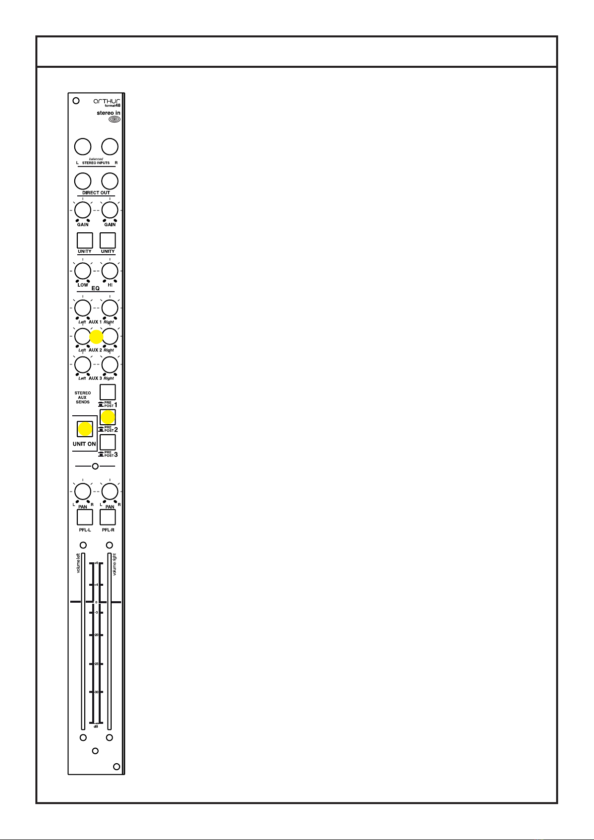
Schertler Arthur ART48 STEREO IN User manual

ACOUSTIC FIDELITY
arthur
ART48 - STEREO IN
USER MANUAL
Assembling instruction on ART48-L/Rmast manual
Version 2017
V2

WARNINGS
PRECAUTIONS
WARNINGS Please read this manual carefully before using your
ROY amplier and observe all safety precautions
Keep this manual for future reference
Do not pour any liquids onto this device, or operate it in excessively humid conditions.
Do not use or install this device near sources of excessive heat. Do not expose it to direct sunlight, or position it in a
dusty environment without any form of protection.
Ensure that the mains voltage does not exceed the value indicated on the back panel.
Do not use this device if either the mains cable or its plug is not in perfect condition. (Replace if necessary.)
If the mains cable needs replacing, it must be done by an appropriately qualied person. The replacement cable must
be exactly the same as the original.
To avoid interference, do not use this device near power transformers, TVs, RF transmitters, electric motors or any
other source of electrical energy.
Do not point a microphone towards any speakers as this could result in feedback (Larsen effect) and ultimate damage
to your device.
Only use the original connection cables – if supplied with the device. Otherwise this could prove both costly and
inconvenient.
To completely disconnect this device from the AC mains, remove the power cable plug from the mains socket.
When cleaning, do not use solvents (e.g acetone or alcohol). These could damage the external nish and the serigraphy.
Do not attempt to service this device. If any malfunction is detected, call the nearest technical assistance centre, or a
specialist technical centre.
To maintain good ventilation, never cover or obstruct the heat sink with blankets, sofas or any other furnishings.
Always leave sufcient clearance between the heat sink and any other surface.
No ammable sources, i.e. candles, should be placed on or near the device.
This device should never be exposed to water, even in small amounts. No object containing liquids should be placed
on or near the device.
This device should only be connected to a mains socket outlet that has a protective ground.
When using or installing this device, always make sure that the mains socket and the mains cable plug are easily
accessible.

IMPORTANT SAFETY INSTRUCTIONS
THE LIGHTNING FLASH WITH ARROWHEAD SYMBOL, WITHIN AN EQUILATERAL TRIANGLE, IS INTENDED TO ALERT THE USER TO THE PRESENCE OF
UNINSULATED “DANGEROUS VOLTAGE” WITHIN THE PRODUCT ENCLOSURE THAT MAY BE OF A SUFFICIENT MAGNITUDE TO CONSITUTE A RISK OF
ELECTRIC SHOCK TO PERSONS.
THE EXCLAMATION POINT WITHIN AN EQUILATERAL TRIANGLE, IS INTENDED TO ALERT THE USER TO THE PRESENCE OF IMPORTANT OPERATING AND
MAINTENANCE INSTRUCTIONS IN THE LITERATURE ACCOMPANYING THE PRODUCT.
WARNING TO REDUCE THE RISK OF FIRE OR ELECTRICAL SHOCK
DO NOT EXPOSE THE APPLIANCE TO RAIN OR HUMIDITY
1) Read these instructions.
2) Keep these instructions.
3) Heed all warnings.
4) Follow all instructions.
5) Do not use this apparatus near water.
6) Clean only with dry cloth.
7) Do not block any ventilation openings. Install in accordance with the manufacturer’s instructions.
8) Do not install near any heat sources such as radiators, heat registers, stoves, or other apparatus (inclu-
ding ampliers) that produce heat.
9) Do not defeat the safety purpose of the polarized or grounding-type plug. A polarized plug has two bla-
des with one wider than the other. A grounding type plug has two blades and a third grounding prong. The
wide blade or the third prong are provided for your safety. If the provided plug does not t into your outlet,
consult an electrician for replacement of the obsolete outlet.
10) Protect the power cord from being walked on or pinched particularly at plugs, convenience recepta-
cles, and the point where they exit from the apparatus.
11) Only use attachments/accessories specied by the manufacturer.
12) Use only with the cart, stand, tripod, bracket, or table specied by the manufacturer, or sold with the
apparatus. When a cart is used, use caution when moving the cart/apparatus combination to avoid injury
from tip-over.
13) Unplug this apparatus during lightning storms or when unused for long periods of time.
14) Refer all servicing to qualied service personnel. Servicing is required when the apparatus has been
damaged in any way, such as power-supply cord or plug is damaged, liquid has been spilled or objects
have fallen into the apparatus, the apparatus has been exposed to rain or moisture, does not operate nor-
mally, or has been dropped.

ART48 - STEREO IN
This CLASS-A unit can receive signals from various sources - mostly audio devices
that generate a line signal (0 dBV) from their output(s). These include effects units, CD
players, tape or digital recorders, preamps of any kind, as well as electronic instruments
such as keyboards and Midi devices.
++
9 9
9 9
++
9 9
9 9
++
9 9
9 9
++
9 9
9 9
++
9 9
9 9
++
9 9
9 9
++
9 9
9 9
++
9 9
9 9
++
9 9
9 9
1 2
++
9 9
9 9
++
9 9
9 9
++
9 9
9 9
-
+
-
+
R
L
0
direct outs
UNITY
UNITY
gain
gain
PFL L
post
pre
Stereo Jack
R
L
pre
hi
low
BUS
PFL
A UX 3
A UX 2
A UX 1
all pots and sw itches in blu color
all plugs and bus in red color
Fader L
ON
post
A UX 2 A UX 3
A UX 1
R
L
+48V
Fader R
ON
PFL R
A UX 2 A UX 3
A UX 1
gain -15dB to +20dB
blockdiagram
modular mixer 3.2017
STEREO LINE UNIT
Stereo Jack

ART48 - STEREO IN
PAN (1.)
Each mono input channel has a PAN knob. Although somewhat
unusual for a stereo input, it makes this particular unit more versatile.
The Stereo In effectively consists of two independent mono input
channels, each with their own controls - with the exception of the
LOW/HI Filter that affects both inputs simultaneously.
The two PAN pots therefore play an important role: When set hard left
and right respectively, the Stereo In unit gives you a stereo input - as
its name suggests. When the PAN pots are set to the centre, you get
a stereo input “switched to mono”. Setting one PAN pot slightly to the
left and the other to the right lets you chamfer the stereo image.
When plugging two independent sources into the Stereo In – such as
a guitar and a mono effect – you can then use the PAN pots to route
each source left and right as required.
INPUT SECTION
As a stereo channel strip, the unit has two input connectors (2.): Left
and Right. These are fully balanced, but use space-saving stereo
phone plugs. The tip connects as usual to the hot signal, the ring to
the cold and the sleeve to the ground. Another advantage of these
phone plugs is that you can connect an unbalanced music signal, for
example from a keyboard, via a simple guitar jack.
Although this stereo input unit is intended to accommodate nominal
line level signals, the input amp’s sensitivity can be adjusted from
-15 dBu to +24 dBu using the GAIN knobs(4.). Left and right input
channels can be separately adjusted. Furthermore, by depressing the
UNITY button(5.), the gain will be set to 1, allowing the signal to ow
- without amplication or attenuation - independently from the Gain
knob setting. This could be particularly useful in a recording situation
for example, where several “line level” devices might be connected to
multiple stereo line input units. Here, all inputs can be evenly set to
an accurate nominal level by depressing the UNITY buttons.
DIRECT OUT(2.)
The Direct Out connections work as a sleeve out or “dry line out post
input amp”. You can connect a simple mono phone jack or a stereo
phone jack to the plugs. The unbalanced line signal will be transmitted
through the “tip” of the phone jacks.
LOW and HIGH Filters(6.)
Line signals do not usually need strong shaping. However, a little
correction of the higher and lower frequencies can be useful. The
stereo LOW and HI lter knobs affect both the left and right inputs
simultaneously.
2.
1.
3.
4.
5.
6.

ART48 - STEREO IN
The UNIT ON button(7.) connects or disconnects the output routing
for all outputs (AUX 1, AUX 2, AUX 3 and L/R), with the exception of
the PFL routing. This function is similar to the MUTE button found
on other mixers, except that its functionality is reversed: When the
UNIT ON button is depressed, all outputs are connected (whereas a
MUTE button in its depressed position disconnects the output). Also,
a MUTE normally only disconnects the L/R routing (the channel’s
fader), whereas this module’s UNIT ON button affects all outputs.
Being able to switch off a channel strip makes sense: For example, it
prevents a signal from still going through to stage monitors, or to the
input of the reverb unit.
THE AUXILIARY SENDS
You will nd the auxiliary sends, labeled STEREO AUX SENDS(8.),
just above the UNIT ON button. There are three knobs for the left
level control of each send (AUX 1, AUX 2, AUX 3) and three knobs for
the right (AUX 1, AUX 2, AUX 3). Therefore, every single AUX send
can be controlled independently from the other sends and from the
other left or right channels.
What’s more, the unit enables every AUX send to “read” the signal
either pre or post fade, courtesy of the Pre / Post buttons(9.) located
near the respective AUX level controls.
If a button is not depressed (orange light), it means that the signal will
arrive “post fade”. When in this position, the relevant auxiliary level
will obviously be controlled by its level knob, but the nal outcome
will also be inuenced by the channel fader’s position. This is very
useful when driving a reverb unit for example, where the proportion of
reverb to original (dry) signal is set by the level knob, then maintained
in proportion while any overall level changes are made using the
channel fader.
If a button is depressed (blue light), the signal will arrive “pre fade”: In
other words, it will be sent to the AUX master without being inuenced
by the position or movement of the channel fader. This conguration
will normally be chosen when driving stage monitors (or similar
devices) through the respective auxiliary master, where inuence
from the main channel fader is not required.
Note: As well as the L/R Master unit, you will also need the AUX Master
unit to benet from all the AUX sends (and other additional options).
The L/R Master can only receive AUX 1, but this is just intended as
a basic conguration where, for example, only one auxiliary send is
needed to operate a reverb device and no stage monitors are being
used.
This AUX Master unit also offers a CLASS-A headphone output,
8.
9.
7.

ART48 - STEREO IN
talkback function and control room output to control the studio
monitors.
PFL(10.)
Each channel (left and right) has a PFL button. When depressed (red
light), the PFL will send the respective signals to the phones or PFL
output on the AUX Master. As well as being a traditional PFL (pre fade
listen), this one also serves as a fourth AUX send, albeit without any
possibility to set the level.
All channels that have the PFL button activated (red light) will be
mixed in the AUX Master unit and sent to the PFL output, controlled
by the PFL fader on the AUX Master.
This function can be useful when an additional monitor is needed, for
example for a singer, where only one signal might be required (in this
case the signal from the “voice channel”).
Note: The PFL section still runs if the CHANNEL ON button is
deactivated (white light).
L / R FADER SECTION(11.)
The channel fader and its associated functionality is probably the
most important part of the output process. In most cases, the signal
going through here will be mixed in the L/R Master and will appear
on the main L/R outputs that drive the recording device or the front-
of-house PA speakers. This is the signal that is usually heard by the
public.
The operation of the L/R fader section is identical to that on other
mixing consoles. The channel faders let you control the total amount
of signal that goes to the master. If you want to completely exclude
the channel’s signal from the L/R Master without changing the fader
position, you can simply deactivate the UNIT ON button (off = white
light). This button will then be acting as a MUTE.
10.
11.

ALL SCHERTLER® PRODUCTS ARE COVERED BY A LIMITED THREE-YEAR WARRANTY (FROM
THE DATE OF PURCHASE) AGAINST MANUFACTURES DEFECTS. DETAILS CAN BE OBTAINED
FROM YOUR LOCAL DEALER/REPRESENTATIVE. SCHERTLER SA STRONGLY BELIEVES IN
“COMMON SENSE” AND THUS, MISUSE OF OUR PRODUCTS ARE NOT COVERED UNDER
RIGHTS OBTAINED THROUGH OUR WARRANTY POLICY OR THAT OF INTERNATIONALLY
RECOGNIZED TERMS AND CONDITIONS.
SCHERTLER SAIS CONSTANTLYAIMING TO IMPROVE ITS RANGE OF PRODUCTS THEREFORE,
SCHERTLER SA RESERVES THE RIGHT TO AMEND PRODUCT
SPECIFICATIONS WITHOUT NOTICE.
THE SCHERTLER® NAME/LOGO ARE REGISTERED TRADE-NAMES/ TRADEMARKS OF
SCHERTLER SA, SWITZERLAND.
All SCHERTLER® PRODUCTS ARE OF PROPRIETARY TECHNOLOGY AND COVERED BY ONE
OF MORE WORLDWIDE PATENTS.
TECHNICAL SPECS
Input impedance:
Maximum input level:
Maximum output level (through L/R):
Sensitivity (accordingly to Gain):
Total Gain (through L/R):
Frequency response: (-3dB)
Low EQ:
High EQ:
Equivalent input noise (EIN):
Distortion (THD+N; @1kHz):
-30dBu input level
0dBu output level
Power consumption:
Size & Weight:
20 kohm
+28dBu (@1kHz; THD<0.5%)
+27dBu (@1kHz; THD<0.5%)
-24dBu to 15dBu
36dB
8Hz – 90 kHz
500 Hz (Shelving) -16dB / +16dB
1.2 kHz (Shelving) -15dB / +14dB
109dB (Direct out, 25dB Gain, 150ohm)
0.09% (2nd harmonic)
0.05% (3rd harmonic)
0.02% (4th harmonic)
0.011% (5th harmonic)
105mA
36x58x475mm; 0,5 kg
Table of contents
Other Schertler Recording Equipment manuals