Schier GB-250-B User manual

Part #: 4055-093-01
Find these instructions online at: schierproducts.com/gb-250-b
Contents
Special Precautions . . . . . . . . . . . . . . . . . . . . . . . . . . . . . . . . . . . . . . . . .2
Getting to Know the GB-250-B . . . . . . . . . . . . . . . . . . . . . . . . . . . . . 4
Buried Installation . . . . . . . . . . . . . . . . . . . . . . . . . . . . . . . . . . . . . . . . 5-8
On the Floor Installation . . . . . . . . . . . . . . . . . . . . . . . . . . . . . . . . . . 9-11
Installation Options . . . . . . . . . . . . . . . . . . . . . . . . . . . . . . . . . . . . . . . . . 12
INSTALLATION GUIDE
GB-250-B 75 GPM 99% Efficient Grease Interceptor
for Indoor/Outdoor Installation
© Copyright 2020 Schier, 04/14/2020

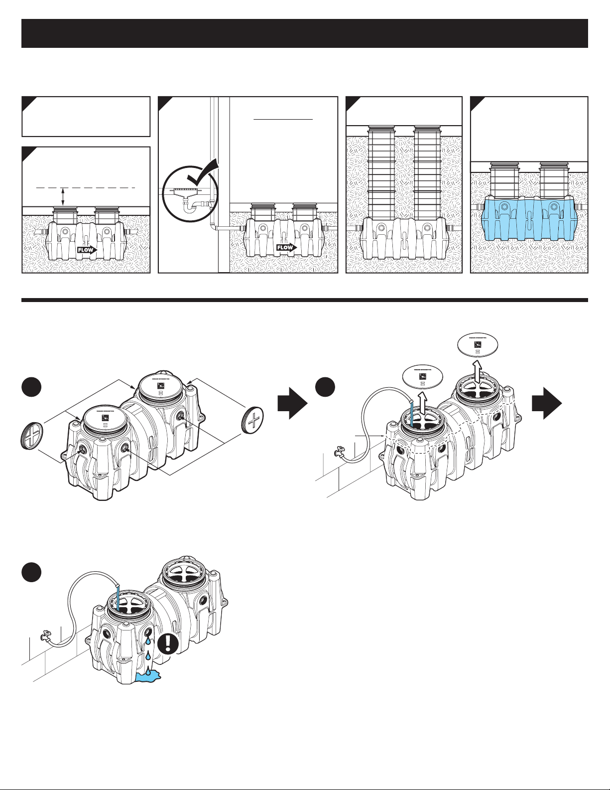
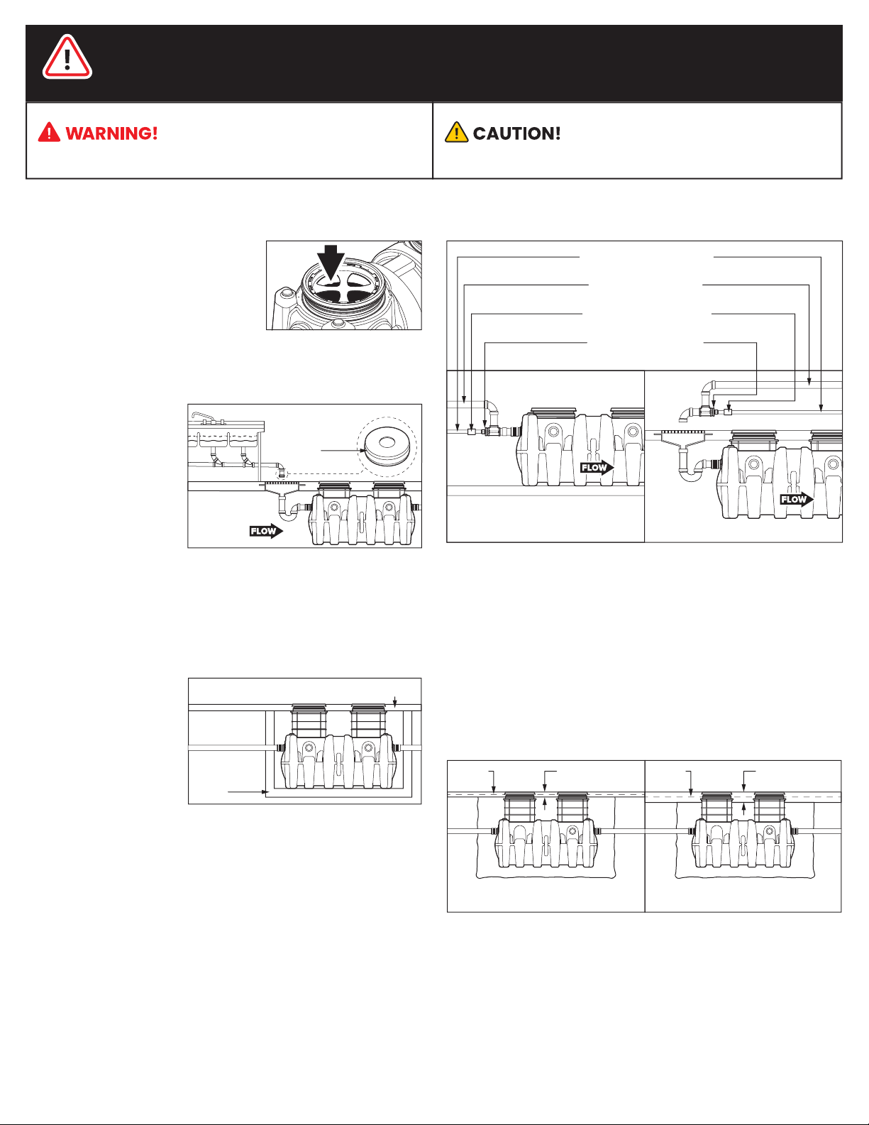
When Installing Interceptor Inside
Fernco or
similar rubber
flow restriction
end cap
SPECIAL PRECAUTIONS
Installation Instructions
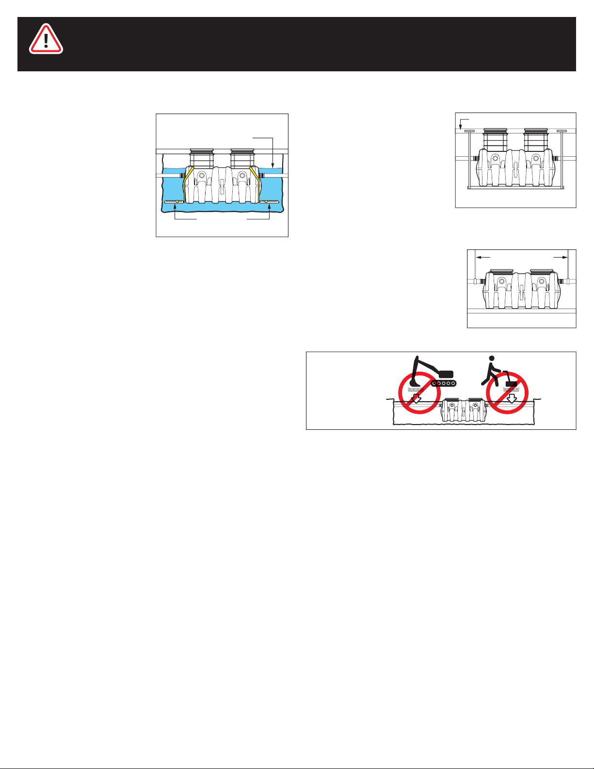
Hydrostatic Slabs (or Pressure Slabs)
High Temperature Kitchen Water
concrete slab subject to hydrostatic pressure
watertight
concrete
vault
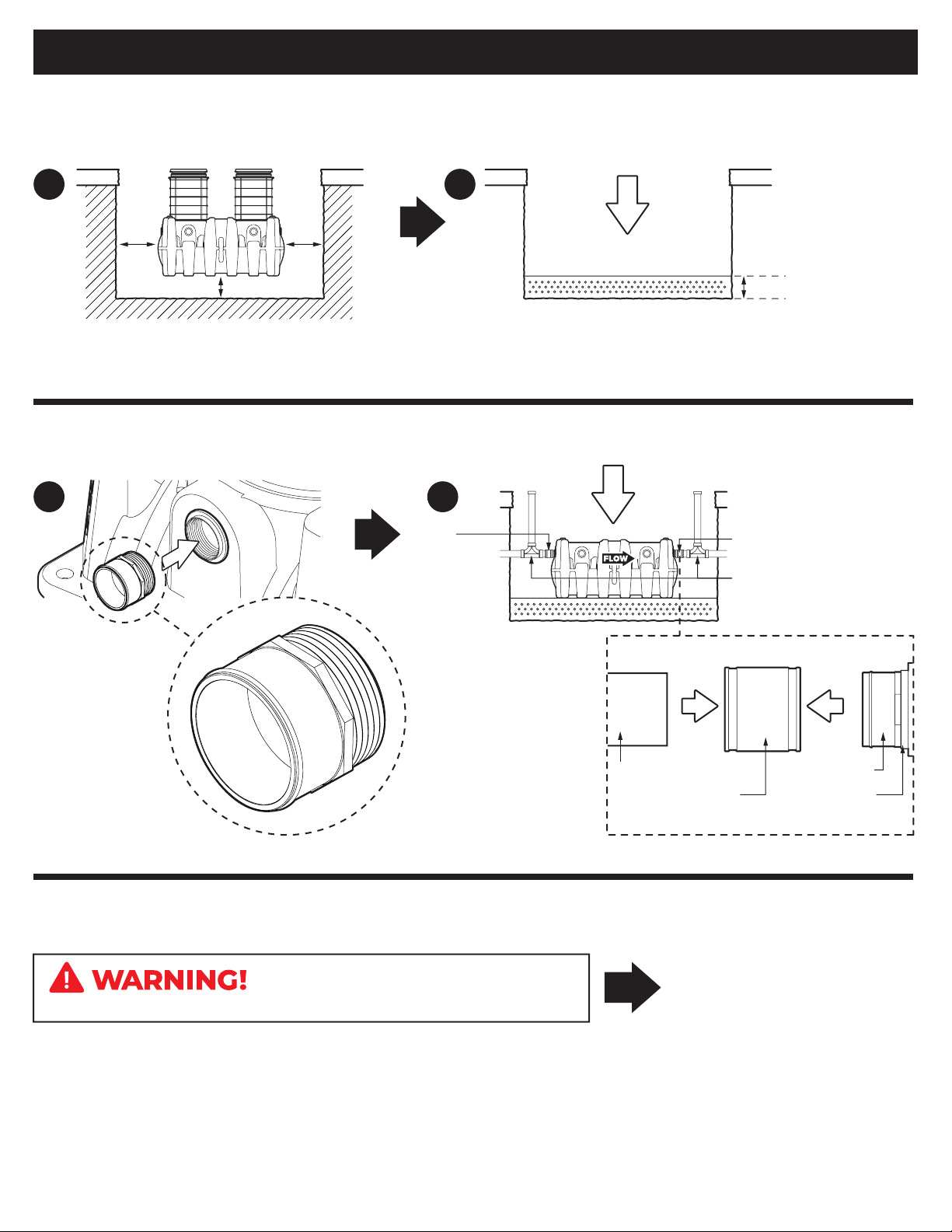
Do not install this unit in any manner
except as described in these instructions.
Doing so may result in property damage, personal injury or death.
DO NOT AIR TEST UNIT OR RISER SYSTEM!
For Schier Grease Interceptor Installations - Failure to follow this guidance
voids your warranty
cold water supply line
high temperature
effluent ( > 150º F)
approved backflow
prevention assembly
DTV (drain water
tempering valve)
directly connected indirectly connected
If water is entering the interceptor at excessive temperature (over
150º F), a drain water tempering valve (DTV) and approved backflow
prevention assembly must be installed. Most state and local
plumbing codes prohibit water above 150º F being discharged into
the sanitary sewer. Water above 150º F will weaken or deform PVC
Schedule 40 pipe, poly drainage fixtures like interceptors and erode
the coating of cast iron (leading to eventual failure).
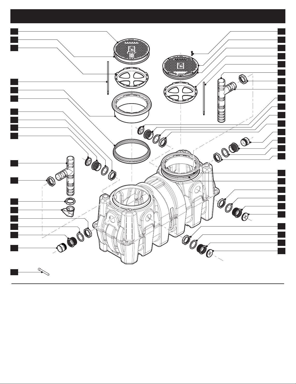
Installation instructions and additional
components are included with the
interceptor. Read all instructions prior
to installation. This interceptor is
intended to be installed by a licensed
plumber in conformance with all
local codes.
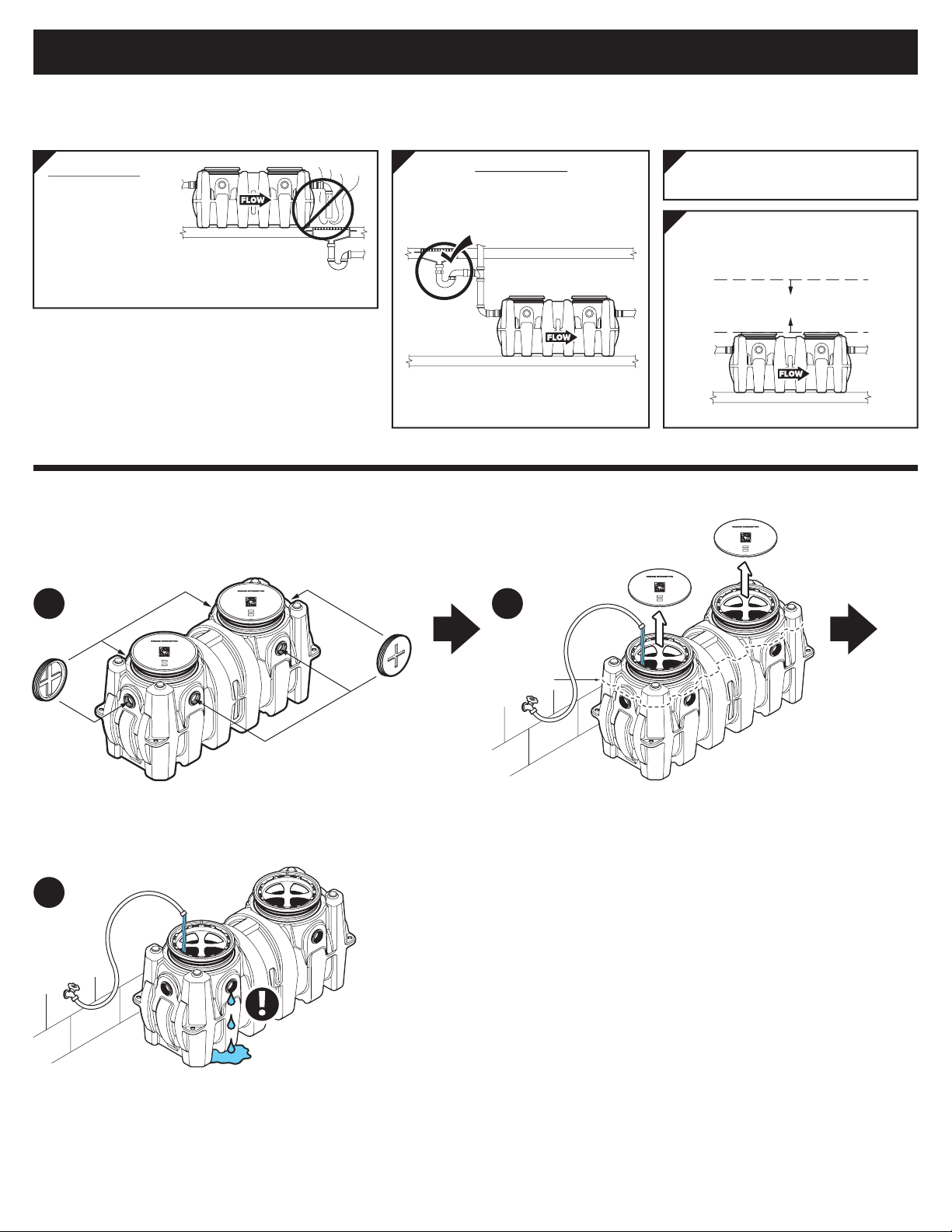
If your dishwashing sink(s)
discharges into a floor
drain/sink (drain), you
must regulate the flow into
the drain to avoid an
overflow of water onto the
kitchen floor. This can be
done by installing a valve
or flow restriction cap on
the sink piping that
discharges into the drain.
See drawing for guidance. For detailed guidance on indirect
connections, go to:
webtools.schierproducts.com/Technical_Data/Indirect_Connections.pdf
When installed under a
hydrostatic slab (slab
designed to withstand
upward lift, usually
caused by hydrostatic
pressure) interceptor
must be enclosed in a
watertight concrete vault.
Interceptor
Interceptor
Interceptor
Interceptor
Interceptor
Interceptor
Interceptor
Interceptor
Interceptor
Interceptor
Interceptor
Interceptor
page 2 of 12
GB-250-B Installation Guide
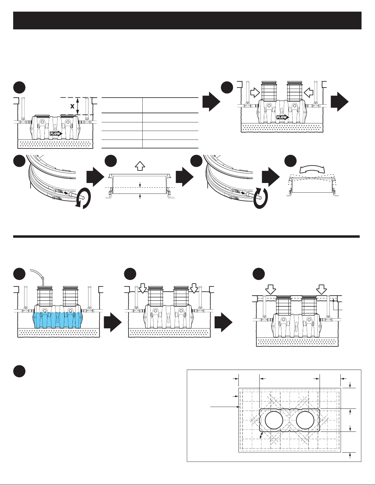
A concrete slab to finished grade with rebar is required when
installing interceptor below grade.
Below Grade Installation Slab Requirements
Pedestrian Traffic or
Greenspace Areas Vehicular Traffic Areas
Rebar
4" min. slab 8" min. slabRebar

SPECIAL PRECAUTIONS
For Schier Grease Interceptor Installations - Failure to follow this guidance
voids your warranty
Install unit on solid, level surface in
contact with the entire footprint of
unit base; for suspended
installations design trapeze to
support the wet weight of the unit.
Do not partially support unit or
suspend unit using metal U-channel
to create a trapeze.
Fully Support Base of Unit
For above grade installations ensure
heavy inlet and outlet piping (such as
cast iron or long runs) is properly
supported or suspended during the
entire installation process to prevent
connection failure or damage to
bulkhead fittings.
Support Inlet and Outlet Piping
pipe supports
concrete floor
suspended installation
DO NOT
COMPACT
BACKFILL
Interceptors and risers are not
designed to withstand water table
height in excess of the top of the
unit when buried (see figure). If it is
possible for this to occur, install the
interceptor and risers in a
water-tight concrete vault or
backfill with concrete or flowable
fill (wet concrete and flowable
backfill should be poured in
stages to avoid crushing the
interceptor). At risk areas include
but are not limited to tidal surge
areas, floodplains and areas that receive storm water. Great Basin™
models that are direct buried in high water table scenarios must be
installed with an anchor kit. Model GB-250 uses model AK1 anchor kit.
max water table height
for direct burial
model AK1
anchor kit
High Water Table Installations
Interceptor
Interceptor
Interceptor
Interceptor
Interceptor
Interceptor
Interceptor
Interceptor
Interceptor
page 3 of 12
GB-250-B Installation Guide

GETTING TO KNOW THE GB-250-B
1. Pickable Cast Iron Cover (standard)
2. Cover Gasket
3. Safety Star (x2)
4. Safety Star Tether (x2)
5. Cover Adapter (x2)
6. Cover Adapter Gasket
Assembly(x2) with Upper and
Lower Stainless Steel Band Clamps
7. Bulkhead Connection Retaining Nut
8. Bulkhead Connection Gasket
9. Inlet Bulkhead Connection
(optional) 4" FPT (x2)
10. 4" Cleanout Plug (x4)
11. Inlet Diffuser
12. Inlet Diffuser Retaining Nut
13. Inlet Diffuser Foot Retaining Nut
14. Inlet Diffuser (Foot)
15. Inlet Bulkhead Connection
(standard) 4" FPT
16. 4" Plain End Fitting (x2)
17. Composite Cover Bolts
and Washers (x8)
18. Bolted Composite Cover (optional)
19. Air Relief/Visual Access
20. Outlet Diffuser Retaining Nut
21. Outlet Diffuser
22. Outlet Bulkhead Connection
(optional) 4" FPT (x2)
23. Outlet Bulkhead Connection
(standard) 4" FPT
24. 7/16" Nut Driver Bit
1 17
18
2
3
4
19
20
21
10
7
8
22
7
5
6
8
22
10
7
8
9
10
2
3
5
6
7
8
9
10
11
12
13
14
7
8
15
16
24
4
7
16
8
23
page 4 of 12
GB-250-B Installation Guide

Special Precautions
BURIED INSTALLATION
1a 1b
1c
Have a Leak?
Call customer care at 913-951-3300
Hours 8am-5pm CST, M-F
1Test tank for water tightness
Cap all connection points with 4" cleanout
plugs using pipe thread sealant or tape
approved for use with plastics.
Remove covers. For base unit testing fill with water to
just above the highest connection.
Inspect unit, connections and gaskets for leaks. Check
water level at specific time intervals per local code.
Max Water Level
Risers are not designed
to retain water
5
Install interceptor as
close as possible to
fixtures being served
1 3
Provide at least 16"
clearance above unit for
routine maintenance.
2
16" min.
3 Risers (94") Max
4
ODOR ALERT!
Interceptor is not a
sewer gas trap.
All upstream fixtures
must be trapped
Fill Line
page 5 of 12
GB-250-B Installation Guide

BURIED INSTALLATION
2b 2c
Remove safety star insert,
leave tethered to unit. Unscrew diffuser retaining nut
and remove inlet diffuser. Unscrew foot retaining
nut and remove inlet
diffuser foot.
Rotate diffuser
top toward
chosen inlet
and replace foot,
ensure it points
toward unit front
wall. Hand tighten
foot retaining nut.
Insert
diffuser into
chosen inlet
and hand tighten
retaining nut.
3e
Cap all unused connection points
with 4" cleanout plugs using pipe
thread sealant or tape approved
for use with plastics.
2 Set Up Inlet Diffuser
2a Choose inlet location. 2d
2e 2f
Side inlet
3 Set Up Outlet Diffuser and Install Cleanout Plugs
3a Choose outlet location.
Side outlet
3b 3c 3d
Remove safety star insert,
leave tethered to unit.
Unscrew diffuser
retaining nut and
remove outlet diffuser.
Rotate diffuser toward
chosen outlet, insert and
hand tighten retaining nut.
Straight-through
Straight-through
page 6 of 12
GB-250-B Installation Guide

Excavate hole at least 12" larger than interceptor on
all sides and 6" deeper than tank bottom.
Lay a level bed of well-packed, crushed aggregate
(approximately 3/4" size rock or sand, with no fines)
in the base of hole.
4a 4b
6" or more
12" 12"
6"
4 Excavate Burial Pit
BURIED INSTALLATION
6 Wet or Air Test Piping Per Local Code
Doing so may result in property damage, personal injury or death.
DO NOT AIR TEST UNIT OR RISER SYSTEM! Have a Leak? Call customer
care at 913-951-3300
Hours 8am-5pm CST, M-F
5b
5 Connect Piping
Screw plain end
fittings (included)
into bulkhead
fittings using
pipe thread
sealant or tape
approved for use
with plastics. 6"
connection types
come pre-installed
from the factory.
5a
4" Plain End
4" FPT
Outlet
Connection
2-Way
Cleanout Tee
Inlet
Connection
page 7 of 12
GB-250-B Installation Guide
DETAIL
Lower unit into pit and
set level. Mechanically
couple inlet and outlet
drainage lines to unit.
Do not solvent weld.
Ensure all upstream
fixtures are trapped.
Vent per local code.
Installation of 2-way
cleanout tees to grade
(by others) is
recommended.
DETAIL
Drain line
Flexible PVC Coupling
Plain End Fitting
Bulkhead Fitting

BURIED INSTALLATION
7 Bring Covers Flush-to-Grade
The GB-250-B is ready for burial depth of 44" from finished grade to bottom of tank (or 13-1/2" to centerline of inlet).
Deeper burials will require extending the Cover Adapters and possibly adding risers.
Measure dimension X to determine riser height needed.
7a
Install risers if required
(see instructions included with FCR2).
7b
Riser Height Risers
Needed Required
0" - 4" None (use adapter)
>4" - 34" FCR2 (x2)
>34" - 64" FCR2 (x4)
>64" - 94" FCR2 (x6)
If required, Cover Adapters
may now be tilted up to
10º in any direction using
gasket flexibility.
7f
Adjust Cover Adapter
heights as needed.
Maintain a minimum
2-1/2" insertion depth.
2-1
/
2" minimum
7d
Loosen the
Cover Adapter Upper
Band Clamp using 7/16"
Nut Driver Bit.
7c
Tighten Upper
Band Clamp to 5 -8 ft.
lbs. of torque using 7/16"
Nut Driver Bit.
7e
8 Backfill and Finished Grade
Fill unit with water for stabilization
and float-out prevention.
8a 8b
Vehicular Traffic Areas:
Minimum 8" thick concrete slab with rebar required.
Thickness of concrete around covers to be determined
by specifying engineer. If traffic loading is required the
concrete slab dimensions shown are for guideline
purposes only. Concrete to be 28 day compressive
strength to 4,000 PSI. Use No. 4 rebar (ø 1/2") grade 60
steel per ASTM A615: connected with tie wire. Rebar to be
2-1/2" from edge of concrete and spaced in a 12" grid with
4" spacing around access openings.
Pedestrian Traffic or Greenspace Areas:
Minimum 4" thick concrete slab with rebar required.
Backfill evenly around tank using crushed
aggregate (approximately 3/4" size rock
or sand with no fines)or flowable fill. Do
not compact backfill around unit.
TOP VIEW 18"
min
45º
18"
min
18"
min
18"
min
Concrete Slab
Rebar
Pour concrete slab to finished grade.
8c
8c1
Rebar
page 8 of 12
GB-250-B Installation Guide

Special Precautions
Install interceptor as close as
possible to fixtures being served
3
ON THE FLOOR INSTALLATION
1a 1b
1c
Have a Leak?
Call customer care at 913-951-3300
Hours 8am-5pm CST, M-F
1Test tank for water tightness
Cap all connection points with 4" cleanout
plugs using pipe thread sealant or tape
approved for use with plastics.
Remove covers. For base unit testing fill with water to
just above the highest connection.
Inspect unit, connections and gaskets for leaks. Check
water level at specific time intervals per local code.
Fill Line
ODOR ALERT!
Interceptor is not a sewer gas
trap. All upstream fixtures must
be trapped
2
ODOR ALERT!
Do not install air
gap on outlet side
of interceptor.
1
Provide at least 16"
clearance above unit for
routine maintenance.
16" min.
4
page 9 of 12
GB-250-B Installation Guide

ON THE FLOOR INSTALLATION
2b 2c
Remove safety star insert,
leave tethered to unit. Unscrew diffuser retaining nut
and remove inlet diffuser. Unscrew foot retaining
nut and remove inlet
diffuser foot.
Rotate diffuser
top toward
chosen inlet
and replace foot,
ensure it points
toward unit front
wall. Hand tighten
foot retaining nut.
Insert
diffuser into
chosen inlet
and hand tighten
retaining nut.
3e
Cap all unused connection points
with 4" cleanout plugs using pipe
thread sealant or tape approved
for use with plastics.
2 Set Up Inlet Diffuser
2a Choose inlet location. 2d
2e 2f
Side inlet
3 Set Up Outlet Diffuser and Install Cleanout Plugs
3a Choose outlet location.
Side outlet
3b 3c 3d
Remove safety star insert,
leave tethered to unit.
Unscrew diffuser
retaining nut and
remove outlet diffuser.
Rotate diffuser toward
chosen outlet, insert and
hand tighten retaining nut.
Straight-through
Straight-through
page 10 of 12
GB-250-B Installation Guide

ON THE FLOOR INSTALLATION
5 Wet or Air Test Piping Per Local Code
Doing so may result in property damage, personal injury or death.
DO NOT AIR TEST UNIT OR RISER SYSTEM! Leak? Call customer care at
913-951-3300
8a – 5p M – F CST
page 11 of 12
GB-250-B Installation Guide
FLOOR BELOW INSTALLATION DETAIL
Mechanically
couple inlet and
outlet drainage
lines to unit. Do not
solvent weld.
Ensure all upstream
fixtures are trapped.
Vent per local code.
DETAIL
Drain line
Flexible PVC Coupling
Plain End Fitting
Bulkhead Fitting
4 Connect Piping
4b
vent per
local code
Screw plain end
fittings (included)
into bulkhead
fittings using
pipe thread
sealant or tape
approved for use
with plastics. 6"
connection types
come pre-installed
from the factory.
4a
4" Plain End
4" FPT
DETAIL

max water table height for direct burial
model AK1 anchor kit
Interceptor
Interceptor
Interceptor
INSTALLATION OPTIONS
1 High Water Table Installations, See Anchor Kit Model AK1
If the installation location is in a high water table
area or at risk are (including but not limited to tidal
surge areas, floodplains and areas that receive
storm water) the GB-250-B must be installed with
Schier model AK1 anchor kit.
page 12 of 12
GB-250-B Installation Guide
Other manuals for GB-250-B
1
Table of contents
Other Schier Lawn And Garden Equipment manuals