Schlage 650 Series User manual

Recommended cutout for 653 Keyswitches.
6-32 thread
2X
1/4" hole
Drill 4X
Remove material to a
depth of 1-3/4" minimum
2-5/8
2-7/8
3-1/4
1-1/2
1-1/4
C
L
C
L
Standard Keyswitch
5A @ 30VAC/VDC Black C
NC Red
NO White
White NO
ATS switch closes
when cover is on.
0.025A @ 28VDC NO White
LED indicator lights
operate @ 12-24VDC
0.025A @ 28VDC
Red (+)
Black (-)
Blocking Ring required for cylinders over 1-1/8"
Thickness = cylinder length - 1-1/8"
Anti-Pullout Tab (optional)
Recommended Cam:
Schlage P/N: B502-191
B502-948 or equivalent
1/16"
Hex set screw
Anti-Tamper Plugs
(HDP only)
653071
650 Series Keyswitches
Installation Instructions & Template
©2013 Ingersoll Rand
(877) 671-7011
653071 Rev. 02/13-d
Information
Template
653 Models mount in a standard single-gang box as shown below. Template may be cut out or follow dimensions for prep of mounting area.
See other side for special application notes.
DO NOT PHOTOCOPY THIS DOCUMENT!
TEMPLATE MUST BE TO SCALE.
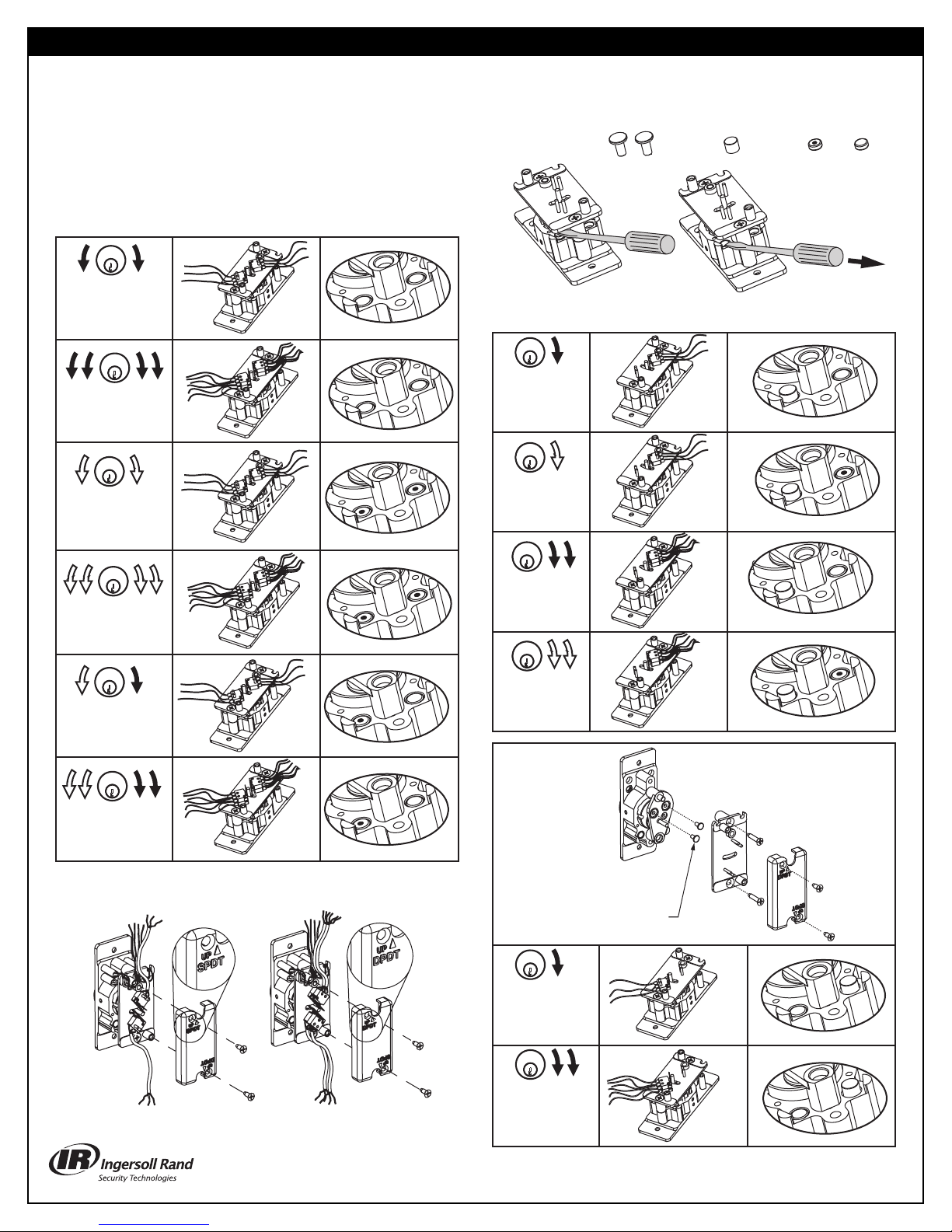
Function Magnet Configuration
Magnet Configuration
Switch Configuration
653-0404
CCW-SPDT-CW
Maintained Maintained
653-1414
CCW-DPDT-CW
Maintained Maintained
653-0505
CCW-SPDT-CW
M Momentaryomentary
653-1515
CCW-DPDT-CW
M Momentary omentary
653-0405
CCW-SPDT-CW
M Momentary omentary
653-1415
CCW-DPDT-CW
M Momentary omentary
Verify switch cover is oriented correctly for switch configuration. Note that
only one, two or four switches can be installed. Three is not recommended.
Install 2 stop pins as shown.
653-041
CCW-SPDT
Maintained
Key can not be
removed when switch
is activated.
653-141
CCW-DPDT
Maintained
Key can not be
removed when switch
is activated.
653-04
SPDT-CW
Maintained
653-05
SPDT-CW
Momentary
653-14
DPDT-CW
Maintained
653-15
DPDT-CW
Momentary
Function Switch Configuration
(Magnets can be
removed, flipped and
reinstalled using a
steel tool as shown.)
Dot Up Dot Down
Spring MagnetStop MagnetStop Pins
Functions
The 653 Keyswitch comes with all parts (except switch assemblies) to make any function shown below.
If switch assemblies are needed, order P/N P653059.
NOTE: The Keyswitch uses magnetic springs to activate.
Dot facing up on Spring Magnet configures momentary
action; dot down configures maintained action. For
maintained key, remove one position (041 and 141
functions). Stop pins will be needed.
This manual suits for next models
1
Other Schlage Switch manuals

Popular Switch manuals by other brands

TP-Link
TP-Link TL-SG2216 user guide

PCB Piezotronics
PCB Piezotronics IMI SENSORS 685A19 Installation and operating manual

Siemens
Siemens SIMATIC NET SCALANCE XM-400 Series operating instructions

Monacor
Monacor NSA-80 operating instructions

Whyte
Whyte WSCR504 instruction manual

TRENDnet
TRENDnet TE100-DX32Rplus user guide


HP
HP aruba 9300-32D Series Installation and getting started guide

HP
HP ProCurve Series 2600 Installation and getting started guide

resideo
resideo 269SN Installation and setup guide

3Com
3Com 3C16487-US datasheet

Panasonic
Panasonic AVHS400AN - MULTI-FORMAT LIVE SWITCHER operating instructions

Maxim
Maxim /MAX4889A instructions