Whyte WSCR504 User manual

DSCR MULTISWITCH
INSTRUCTION MANUAL
www.whytetechnologies.com
MODELS:
WSCR504
WSCR506
WSCR508
WSCR512
WSCR516

Safety
Precauons
Guarantee
General Descripon
Product Descripon
Technical Descripon
Installaon Instrucons
Commissioning the Mulswitch
Example Conguraon
Specicaons
3
3
3
4
5
6
8
11
12
14
CONTENTS
www.whytetechnologies.com
2www.whytetechnologies.com 3
Whyte
SAFETY
The Mulswitches are intended for indoor use only. Do not install the Mulswitch
in damp, humid, hot or dusty areas.
Switch o and remove the power supply when making connecons to the
Mulswitch to avoid damaging the unit.
Always earth bond the Mulswitch using the Earth Bonding Lug and/or the
Earth Terminal Bars to a suitable earth bonding point using minimum 4mm²
diameter earth cable.
PRECAUTIONS
To ensure trouble free operaon:
Do not remove the cover of the Mulswitch or disassemble it as this will
invalidate the guarantee.
The female F connectors on this unit were designed for use with '100' type
coaxial cable with a centre core diameter of 1mm². When using larger CT125
or CT167 cables, you must ensure that suitable F connectors with reducing
pins are used otherwise damage to the unit will occur which will invalidate the
guarantee.
Do not over ghten the F connectors (nger ght only).
GUARANTEE
All Whyte products are guaranteed for a period of 4 years from the date of
purchase against defects. Within this guarantee period, Whyte Technologies will
repair or replace the faulty product. In the unlikely event, please return any faulty
products to your dealer.

www.whytetechnologies.com
4www.whytetechnologies.com 5
Whyte Series D is a range of advanced Cascadable Hybrid dSCR Mulswitches.
Seamless integraon with convenonal IRS Systems due to extremely low power
consumpon, low loss passive trunks and high gain TERR, make the new Series
D range from Whyte the most versale and easy to install dSCR Mulswitch
range available.
The Series D range can be directly conjoined with Series 5 convenonal
Mulswitches using the supplied F type couplers to seamlessly create Hybrid
IRS Systems.
Use Series 5 Launch Ampliers, Taps, Spliers and Power Supply Units to create
large scale dSCR only or Hybrid IRS Systems.
Each Subscriber Output provides Satellite (SkyQ dSCR & Legacy), TV and
Radio. Satellite subscriber signal levels in both Legacy and dSCR mode are
automacally set to 85dBμV (self-commissioning/AGC). Dscr and Legacy mode
is automacally detected and switched over on a per-subscriber port basis.
Terrestrial signal levels are controlled via a manual Gain Control knob and a
selectable Protean Tap which permits a wide range of TERR input signal levels
ranging from 50 to 108dBμV.
The recepon of 2 satellites can easily be achieved by ulising 2 Wideband
LNB’s and switching the unit to Wideband LNB mode.
The unit can be powered directly via the DC input port or be remotely powered
via the trunk lines.
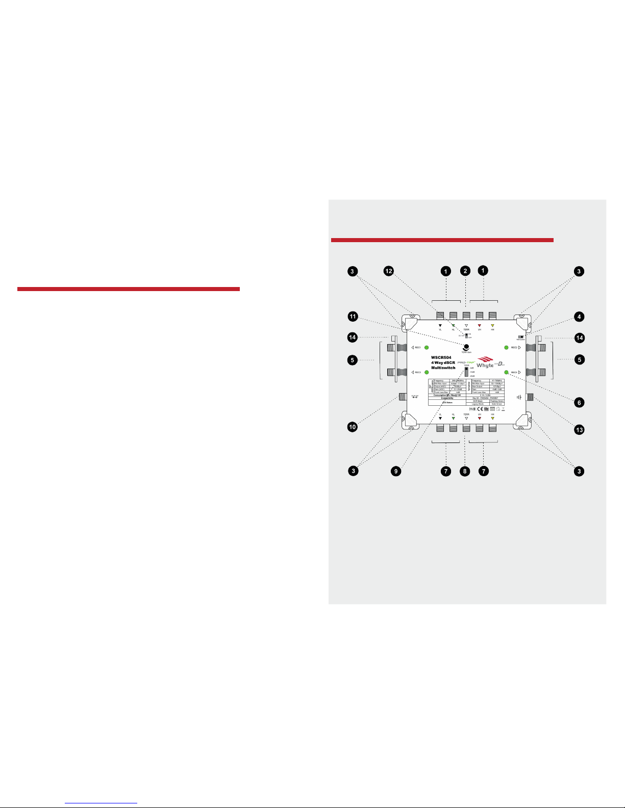
GENERAL DESCRIPTION
1. Inputs Satellite
2. Input Terrestrial
3. Corner Mounng Brackets
4. LNB Selector Switch
5. Subscriber (REC) Outputs
6. Subscriber Output Status Indicator
7. Trunk Output SAT
8. Trunk Output TERR
9. TERR Protean Tap
10. Auxiliary DC Input
11. TERR Gain Control
12. TERR 12V DC Switch
13. Earth Terminal
14. Earth Terminal Bar
PRODUCT DESCRIPTION
The Guarantee will be deemed as void if the serial number on the product
is removed, damaged or illegible. The Guarantee excludes defects caused by
incorrect use, accidental damage, disassembly, water/re/lightning damage or
lack of venlaon.

www.whytetechnologies.com www.whytetechnologies.com
67
TECHNICAL DESCRIPTION
DC POWERING
The Whyte Series D range can be Line Powered via any of the SAT input and
output Trunk Lines. All SAT Trunk Lines are DC passing, whilst the TERR Trunk
Line is DC isolated.
The Mulswitches have an Auxiliary DC Input which will power the Mulswitch
as well as provide power to the SAT input and output Trunk Lines when ed
with a Whyte PSU.
A 12V DC switch is available to power a Mast Head Amplier connected to the
TERR input. If a Mast Amplier is not being used this must be le in the OFF
posion.
SUBSCRIBER PORT MODE INDICATION
Each Subscriber Port has an LED indicator to conrm the mode status.
Legacy Mode: Solid Green
dSCR Mode: Blinking Green
Legacy Mode:
This is the default mode of the Mulswitch. In this mode the Mulswitch
funcons like a convenonal legacy Mulswitch.
dSCR Mode:
When a dSCR Set Top Box is connected, the corresponding port will acknowledge
the dSCR DiSEqC commands and switch to dSCR mode. To revert back to legacy
mode the power to the Subscriber Port needs to be interrupted momentarily. A
reboot of the Mulswitch is NOT necessary to revert back to legacy mode.
STANDALONE MODE
Series D Mulswitches can be used in stand alone mode when powered directly
Whyte
via the 18V Auxiliary Input by using a Whyte Power Supply Unit (sold separately).
Any unused (open) SAT/TERR Trunk Outputs must be terminated using 75Ω DC
Blocked F-Type Terminators.
CASCADE MODE
Mulple Whyte Series D Mulswitches can be connected in cascade using the
supplied F Type Couplers. In Cascade Mode, the PSU can be connected to any
Series D Mulswitch, Splier, Tap or Amplier within the system for ease of
installaon. Hence, all Series D Mulswitches will be remotely powered via the
SAT Trunk Lines.
Care must be taken to select the appropriate type and number of PSU's required
depending on the current requirements of the system as a whole. Remember
to calculate the total current consumpon of all Mulswitches, Ampliers and
LNB's within the system.
Always terminate the SAT/TERR Trunk Outputs of the last Mulswitch in a
cascade using 75Ω DC Blocked F-Type Terminators.
QUATTRO/WIDEBAND LNB SWITCH
The Series D range is compable with both Quaro and Wideband LNB’s. To
enable compability with a Quaro LNB (5 Wire Trunk) place the switch in the
posion marked “Q”. To enable compability with a Wideband LNB (3 Wire
Trunk) place the switch in the posion marked “WB”.
2 SAT RECEPTION
The recepon of two satellites can be achieved via a 5 wire trunk by ulising 2
Wideband LNB’s. The required satellite can then be selected by the STB using
simple diseqc Satellite A and B commands.

INSTALLATION INSTRUCTIONS
MOUNTING THE MULTISWITCH
Select a suitable locaon to install the Mulswitch. Do not install the Mulswitch
in damp, humid, hot or dusty areas. Using the screw slots on the Corner Brackets,
secure the Mulswitch using the appropriate xing screws and wall plugs to suit
the relevant wall surface or cabinet.
CONNECTING THE SAT & TERR INPUTAND OUTPUT TRUNK CABLES:
Use a suitably sized Satellite Dish to provide adequate signal levels from the
satellite being received. Ensure that the Satellite Drop Cables are connected
correctly to the LNB's. Ensure that the F Connectors are properly sealed against
water ingress. If a Composite Cable (mul core coaxial cable) has been used,
ensure that the outer jacket is not facing upwards and cannot collect rain water.
Check the Terrestrial Drop Cable and ensure that this has also been sealed
against water ingress. If a Triplexer has been used to combine FM and DAB
aerials with the UHF Terrestrial Aerial, ensure that this is also water ght. Ensure
that all drop cables have drip loops prior to their entering the building.
Connect the SAT and TERR drop cables to the corresponding Satellite and TERR
Inputs on the Mulswitch. Connect any addional Mulswitches or Trunk Cables
to the Satellite & TERR Trunk Outputs as applies. Ensure that you terminate the
last Mulswitch in a cascade using 75Ω DC Blocked F-type Terminators.
www.whytetechnologies.com www.whytetechnologies.com
8 9
Whyte
EARTH BONDING
Earth bond the Mulswitch to the Earth Bonding Lug and/or the Earth Terminal
Bars using minimum 4mm² Earth Bonding Cable. It is best pracse to earth bond
across all Mulswitches using a single unbroken Earth Bonding Wire. To achieve
this, strip away 3cm of the insulaon of a length of 4mm² Earth Bonding Wire.
See Figure 1.
Unscrew the Earth Bolt on the Earth Terminal Bar to provide enough clearance
to wrap the Earth Bonding Wire around the Earth Bolt. See Figure 2.
Tighten the Earth Bolt and route the Earth Bonding Wire to all other Earth
Terminal Bars and terminate as detailed above. Make sure that the Earth Bonding
Cable is connected directly to the building’s PME.

www.whytetechnologies.com www.whytetechnologies.com
10 11
CONNECTING THE POWER SUPPLY UNIT (PSU)
Calculate the total current consumpon of the Mulswitch(es), LNB and
any Launch Ampliers that make up the complete IRS System. The current
consumpon of the Series D Mulswitch range can be found in the Specicaon
secon of this manual. If in doubt, assume the current consumpon of each
LNB to be 200mA max (0.2A). Connect a suitable Whyte PSU to the Auxiliary
18V DC Input. If more than one PSU is required, the addional PSU(s) may be
connected to any other Mulswitch, Launch Amplier, Tap or Splier within the
system. When all connecons have been made, connect the PSU to a 240V
supply to power up the IRS System. It is highly advisable to isolate and hence
divide the system in to DC Groups containing only a single PSU per group, by
using F-type DC blockers (not supplied).
Connecting the Subscriber Cables
Terminate the Subscriber Cables with good quality F Connectors and connect to the Subscriber
Outputs. The F Connectors should be fitted to the coaxial cable correctly, ensuring that the centre
core protrudes 3mm above the F Connector body. See figure 3. Ensure that you do not exceed the
bending radius of the Coaxial Cable being used. The Subscriber Cables may be arranged either
side of the Multiswitch before being terminated and connected. If required, the Subscriber Cables
may be arranged to one side of the Multiswitch, with the cables passing under the Multiswitch before
being terminated and connected to the Subscriber Outputs on the opposite side. See figure 4.
Always use CAI approved high quality coaxial cable.
Connecting the Power Supply Unit (PSU)
The PSU must be fixed to the relevant wall surface using the appropriate fixings. Connect the DC F-
type lead to the 18V DC Input of the Multiswitch.
Once all connections have been made, connect the plug to a 240V socket to power up the
Multiswitch. If a local mains supply is not available such as in lofts and outdoor cabinets, the Power
Supply Unit may be conveniently fitted elsewhere whereby the 18V DC F-Type lead may be extended
using coaxial cable.
5
Whyte
Earth Bonding
Earth bond the Multiswitch to the Earth Bonding Lug using minimum 4mm² Earth Bonding Cable.
Make sure that the Earth Bonding Cable is connected directly to the building’s PME (Protective
Multiple Earthing) point.
Figure 3
3mm
Figure 4
Whyte
COMMISSIONING THE MULTISWITCH
See Figure 4:
1. Connect a spectrum analyser to any Subscriber Output of the rst Mulswitch
2. Set the TERR Pro-Tap to -20dB
3. Set the Spectrum Analyser to Terrestrial. Using the TERR Gain Control adjust
the Terrestrial signal to the required digital channel power level. If the signal
cannot reach the required level, set the TERR Pro-Tap to -10dB and readjust the
TERR Gain Control. If required, set the Pro-Tap to -0dB and readjust the Gain
Control.
4. Check the SAT signal levels in Legacy and dSCR mode. These will not require
adjustment as they are self-commissioned using Automac Gain Control.
5. Repeat the above for all other Mulswitches in the IRS System as applies.
CONNECTING THE SUBSCRIBER CABLES
Terminate the Subscriber Cables with good quality F Connectors and connect to
the Subscriber Outputs. The F Connectors should be ed to the coaxial cable
correctly, ensuring that the centre core protrudes 3mm above the F Connector
body. See gure 3. Ensure that you do not exceed the bending radius of the
Coaxial Cable being used.
USER BAND FREQUENCIES

www.whytetechnologies.com www.whytetechnologies.com
12 13
Whyte
EXAMPLE CONFIGURATION
Figure 4
EXAMPLE CONFIGURATION
Hybrid IRS

WSCR508 8-Way dSCR
WSCR512 12-Way dSCR
WSCR516 16-Way dSCR
290-2340MHz
290-2340MHz
290-2340MHz
47-790MHz
47-790MHz
47-790MHz
Yes
Yes Yes
4 SAT + 1 TERR 4 SAT + 1 TERR 4 SAT + 1 TERR
8
12
16
Yes
Yes
Yes
No
No
No
-4dB
-4dB
-4dB
-4dB
-4dB
-4dB
-35dB~+25dB (AGC)
-35dB~+25dB (AGC)
-35dB~+25dB (AGC)
+8dB±2dB
+8dB±2dB
+8dB±2dB
AGC
AGC
AGC
15dB
15dB
15dB
0/-10/-20dB
0/-10/-20dB
0/-10/-20dB
62 ~ 117dBµV
62 ~ 117dBµV
62 ~ 117dBµV
52 ~ 108dBµV
52 ~ 108dBµV
52 ~ 108dBµV
85 dBµV (AGC)
85 dBµV (AGC)
85 dBµV (AGC)
107 dBµV
107 dBµV
107 dBµV
Yes Yes Yes
18V DC 18V DC 18V DC
Yes
Yes
Yes
Yes
Yes Yes
No
No
No
Yes Yes Yes
TBA TBA TBA
Legacy
Sky UK dSCR
EN50494
EN50607
Legacy
Sky UK dSCR
EN50494
EN50607
Legacy
Sky UK dSCR
EN50494
EN50607
16 16 16
22K Tone & Voltage
22K Tone & Voltage
22K Tone & Voltage
Diseqc commands
Diseqc commands
Diseqc commands
>43dB
>43dB
>43dB
>36dB
>36dB
>36dB
>10dB / >10dB
>10dB / >10dB
>10dB / >10dB
>8dB / >8dB
>8dB / >8dB
>8dB / >8dB
>8dB
>8dB
>8dB
LED LED LED
LED LED LED
Yes Yes Yes
Yes Yes Yes
TBA TBA TBA
TBA TBA TBA
Model
WSCR504 4-Way dSCR
WSCR506 6-Way dSCR
Frequency Range
SAT
290-2340MHz
290-2340MHz
TERR
47-790MHz
47-790MHz
Quattro/Wideband LNB Switch
(2 SAT reception when using 2 x WB LNB’s)
Yes Yes
Inputs (F Connector) 4 SAT + 1 TERR 4 SAT + 1 TERR
Trunk Outputs (F Connector) 4 SAT + 1 TERR 4 SAT + 1 TERR
Tap Output Ports (F Connector) 4 6
Trunk DC Pass
SAT
Yes
Yes
TERR
No
No
Trunk Through
Loss (nom)
SAT
-4dB
-4dB
TERR
-4dB
-4dB
Gain
SAT
-35dB~+25dB (AGC)
-35dB~+25dB (AGC)
TERR
+8dB±2dB
+8dB±2dB
Gain Control
SAT
AGC
AGC
TERR
15dB
15dB
Protean Tap (ATT Switch) TERR 0/-10/-20dB 0/-10/-20dB
Min/Max Input
Signal Level
SAT
62 ~ 117dBµV
62 ~ 117dBµV
TERR
52 ~108dBµV
52 ~ 108dBµV
Max Output
Signal Level
SAT (Legacy/dSCR)
85 dBµV (AGC)
85 dBµV (AGC)
TERR
107 dBµV
107 dBµV
TERR 12V DC Supply (switchable) Yes Yes
Power Supply Voltage
18V DC
18V DC
Powering
Via DC In
Yes
Yes
Via SAT trunks
(remote)
Yes Yes
Via STB
No
No
Power from DC In to Input & Output SAT Trunks Yes Yes
Consumption Min / Max @18V 0.1A/ 0.28A TBA
Compatibility (Auto Switching)
Legacy
Sky UK dSCR
EN50494
EN50607
Legacy
Sky UK dSCR
EN50494
EN50607
dSCR User Bands per port 16 16
Switching Commands
Legacy
22K Tone & Voltage
22K Tone & Voltage
dSCR
Diseqc commands
Diseqc commands
Isolation
Tap Port to Port
>43dB
>43dB
Trunk Port to Port
>36dB
>36dB
Return Loss
SAT Trunk In/Out
>10dB / >10dB
>10dB / >10dB
TERR Trunk In/Out
>8dB / >8dB
>8dB / >8dB
Tap Output Ports
>8dB
>8dB
SCR/Legacy Mode Indication (per port) LED LED
Power Indication LED LED
Earth Lug Yes Yes
Earth Terminal Bars (tap output ports) Yes Yes
Dimensions (HxWxD) 160x215x43mm TBA
Weight 450g TBA
Whyte
www.whytetechnologies.com www.whytetechnologies.com
14 15
SPECIFICATIONS
SPECIFICATIONS
Yes
Yes
WSCR506 6-Way dSCR
In the interest of connuous improvement, all specicaons of products are subject to change without noce.

www.whytetechnologies.com
@WhyteTech
@WhyteTechnologies
Whyte Technologies
@WhyteTechnologies
Whyte Technologies
Chevron Distribuon Ltd
Unit 12 - 13,
Watermill Business Centre
Edison Road
Eneld, EN3 7XF
Phone: 0330 999 1980
E-mail: inf[email protected]
This manual suits for next models
4
Table of contents
Other Whyte Switch manuals