10707 Stancliff Rd. Houston, TX 77099
Rose Electronics – Europe: +49 (0)2454 969442 Rose Electronics – Asia: +65 6324 2322
DS-VSP 1.7 Copyright 2004 Rose Electronics. All rights reserved WWW.ROSE.COM
Typical Application
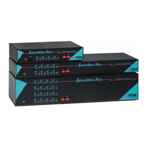
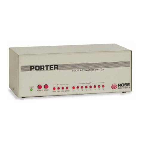
Introduction SuperSwitch, a powerful, yet low-cost,
peripheral sharing unit interconnects up to nine computers
and peripherals using common serial and parallel
interfaces. Here are some of the features that make it a
practical investment for the budget-conscious.
Basic Concepts This versatile microprocessor controlled
switch has seven serial and two parallel ports for
connecting any combination of computers and
peripherals. Destinations are selected using an easy pop-
up menu, keyboard commands, batch files, or by other
ways. SuperSwitch activates the port connection when
you send data from your application or print program. Data
from each port is sent to its destination immediately if the
destination device is available. If the destination device is
busy, the data is queued by priority for its turn to access
the device.
Buffer Memory The SuperSwitch buffer is dynamically
allocated. As the data in the buffer is sent to its
destination, the buffer is reclaimed to be used again.
Allocating memory in this way protects against lockout
and ensures that large jobs always have adequate memory
available. It also maximizes productivity by returning
control of the computer to the operator faster and by
significantly reducing printing time. SuperSwitch’s 64K
buffer is expandable to 1Mb.
Cables You connect SuperSwitch to your equipment
using standard cabling with DB25 serial connectors and 36
pin female Centronics parallel connectors. Cables are
ordered by length and the type of device that is being
connected. Please refer to the cabling section for further
information.
Configuration SuperSwitch is configured through a PC
connected to port 0 using simple installation software
provided. A pop-up configuration menu displays setup
parameters for all ports and allows you to change them as
needed. You choose whether each port is to be connected
to a computer, printer, plotter, or modem. Other settings
for each port are its name, default destination, and priority.
For serial ports you also assign its communication
settings. Configuration is stored in the switch’s non-
volatile memory.
Part Numbers
SS-9 7-serial and 2-parallel port
SS-9S 9-serial ports
/2 256K buffer option
/5 512K buffer option
/10 1Mbyte buffer option
/RM-MP 19" x 5.25" black anodized rack
mount
/RM-MP/23 23" rack mount
/422 RS422 option for serial models
/220FM 220 VAC floor mount adapter
Specifications
Size 10.5 W x 5.0 D x 3.5 H (in)
26.7 W x 12.7 D x 8.9 (cm)
Weight 8 lbs. / 3.63 kg
Power 110VAC, 10VA wall adapter,
220 VAC optional
Connectors Power: DIN5
Serial: DB25 Female
Parallel: 36 pin Female Centronics
Memory Field upgradeable to 1MB
Chassis Fully shielded, tan painted steel
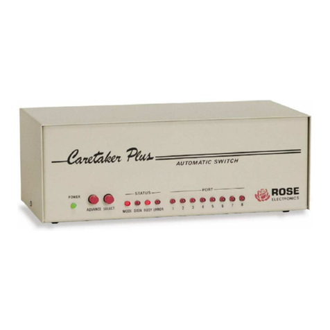
Front Panel LEDs: Buffer, Data, Busy, Ports 0-8
Controls Advance and Select switches
Serial protocol* EIA asynchronous RS232D
Parallel protocol** TTL Centronics
Serial flow control DTR/DSR or* XON/XOFF to buffer;
DSR/DTR sent through for modem
Parallel flow control STB/ACK/BUSY
Serial baud rate 50 - 19,200 BAUD*
Word Size 5, 6, 7, or 8
Parity None, odd, even, mark, space
Stop Bits 1 or 2**
Environmental 32°- 131°F (0°-55° C)
0%-80% non-condensing
relative humidity
Approvals CE
* Each port is individually programmable
** Each parallel port is programmable as a computer
port or printer port
Rearview – model SS-9
