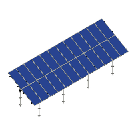
Schletter SECT User manual

SECT
INSTALLATION MANUAL
SECT (patent pending) in flush,
north or east-west variants.

SECT | V1 | INSTALLATION MANUAL | 202102 2
SCHLETTER SOLAR GMBH | SUBJECT TO CHANGES
Table of contents
SECT INSTALLATION GUIDE ........................................................................................................... 3
TOOLS NEEDED ............................................................................................................................... 3
FURTHER REQUIRED DOCUMENTATION.................................................................................. 3
TIGHTENING TORQUE ................................................................................................................... 3
SAFETY INSTRUCTIONS................................................................................................................ 3
1. INTRODUCTION.......................................................................................................................... 4
1.1. Overview............................................................................................................................... 4
1.2. Compliance and certification .......................................................................................... 4
1.3. Orientation options............................................................................................................ 4
1.4. No reach’ installation ........................................................................................................ 5
1.5. Types of roof fixings.......................................................................................................... 5
2. LAYOUT AND ASSEMBLY ......................................................................................................... 6
2.1. Fixing spacing ..................................................................................................................... 6
2.2. Length of column or row.................................................................................................. 6
2.3. Assembly .............................................................................................................................. 7
2.4. Joining channels ................................................................................................................. 9
2.5. Earthing................................................................................................................................. 9
3. INSTALLATION USING ROOF CLAMPS .............................................................................. 10
4. INSTALLATION USING ROOF SCREWS ............................................................................. 11
5. INSTALLATION USING CONCRETE ANCHORS ................................................................ 12
6. CABLE TRAYS............................................................................................................................ 12
6.1. Cable trays on a sheet metal roof .............................................................................. 12
6.2. Cable trays on a concrete roof..................................................................................... 13
6.3. Cable trays on another channel .................................................................................. 13
7. ELECTRICAL DESIGN CONSIDERATIONS......................................................................... 14
8. MAINTENANCE.......................................................................................................................... 14

SECT | V1 | INSTALLATION MANUAL | 202102 3
SCHLETTER SOLAR GMBH | SUBJECT TO CHANGES
SECT INSTALLATION GUIDE
TOOLS NEEDED
13 mm socket to suit flanged hex head of M8 fasteners
FURTHER REQUIRED DOCUMENTATION
Product range doesn’t include roof hooks
TIGHTENING TORQUE
Screw connections M8: 15 Nm
Exception: Wood screws: with depth stop
SAFETY INSTRUCTIONS
Planning, installation and commissioning of the solar power system must only be performed by
qualified technical personnel. Improper execution can result in damage to the system and
premises and endanger persons.
Falling hazard! Working on the roof as well as ascending and descending poses a risk of falling.
It is vital to observe accident prevention regulations and use appropriate fall protection
equipment.
Injury hazard! Falling objects pose a risk of injury to people. Prior to installation, set up
barriers in the hazard area to warn people nearby.

SECT | V1 | INSTALLATION MANUAL | 202102 4
SCHLETTER SOLAR GMBH | SUBJECT TO CHANGES
1. INTRODUCTION
Thank you for choosing the SECT solar panel roof mounting system. Made from custom-
designed aluminium extrusions and components, SECT streamlined design and improved frame
strength greatly simplify solar panel installation. SECT is backed by a 10-year warranty and is
compliant with the AS/NZS 1170.2:2011/Amdt 2:2012 on wind actions and AS/NZS
16641.1:1997 on aluminium structures.
1.1. Overview
SECT solar PV arrays are assembled on the roof using channel (or rail), brackets and clamps.
The product is suitable for commercial format modules (approximately 2 m x 1 m) with frame
heights of 35 mm. Modules are held in one of three possible orientations:
10° tilt, back-to-back, so that each module shields the next from the wind, also called “east-west”
10° tilt, with each module facing in the same orientation, also called “north”
0° tilt, also called “flush”
1.2. Compliance and certification
SECT is supplied with a generic certification that suits most buildings, covering wind regions A,
B & C, terrain category 2 & 3. Custom certification is also available, e.g., for terrain category
1.5 or 1.0 (near open water), including an assessment of the site wind speed and the as-built
conditions of the roof sheet and roof frame. Certification is provided by Tensys Engineers. If the
roof is exposed to higher wind loads, such as near open water (Terrain Category 1) please
contact Schletter for guidance.
1.3. Orientation options
SECT can be installed in landscape ‘columns’ that proceed from gutter to roof ridge; or portrait
‘rows’ that proceed from side to side. The default method is in landscape ‘columns’, where the
fixing spacing is equal to the purlin spacing. Each column of modules is fixed to two channels
using edge and centre brackets that incline the modules at 10 degrees. Electrical cables can
run in the channels. Modules must have a 40 mm frame.
SECT in a
column
SECT in a row

SECT | V1 | INSTALLATION MANUAL | 202102 5
SCHLETTER SOLAR GMBH | SUBJECT TO CHANGES
1.4. No reach’ installation
Each module is held at four points using brackets, either edge, centre or flush. Each bracket is
double sided, with one side offering a mechanical clamping function, and the other side offering
a “push in” function using a C-shaped profile. Assembly occurs by sliding the far edge of the
module into the C-shaped profile, then clamping at the near edge. This way, installers don’t
have to reach a meter over the module to tighten a fastener.
1.5. Types of roof fixings
SECT can be fixed to the roof using:
roof clamps with EPDM rubber sheets,
channel feet on roof screws, or
channel feet on concrete anchors.
Edge bracket SPEB-40
Centre bracket SPCB-40
Channel fixed to channel foot, then
roof clamp
Channel fixed to channel foot, then
roof screws to the purlins
Flush bracket SPFB-40

SECT | V1 | INSTALLATION MANUAL | 202102 6
SCHLETTER SOLAR GMBH | SUBJECT TO CHANGES
2. LAYOUT AND ASSEMBLY
2.1. Fixing spacing
When SECT is installed in columns, the fixing spacing (distance between channel feet) is equal
to the purlin spacing, because a channel foot is used at each point where a channel crosses a
purlin. Also, the channels need to be extended past the modules to reach the next purlin
(maximum allowable cantilever between fixing and edge of module is 100 mm). When SECT is
installed in rows, the fixing spacing can be reduced down to the roof sheet rib spacing.
However, the purlin spacing needs to match the approved “clamping zones” defined by the
module installation manual, e.g., from 1000 to 1600 mm, to fit the typical “10-25 % clamping
zones” for a 2 m long module.
2.2. Length of column or row
SECT suits industry standard modules with nominal dimensions of 1000 x 2000 mm and
a 40 mm frame height. The length of a column of modules is a function of the exact width of
the modules used. For example, if JA Solar JAM72S10 modules are used, they have a width
of 996 mm and each pair of modules has a ‘repeat distance’ of 2021 mm.
SECT in a column
(or landscape format)
SECT in a row
(or portrait format)
Repeat length of each pair of JA Solar JAM72S10 modules (996 mm wide) is 2021 mm.

SECT | V1 | INSTALLATION MANUAL | 202102 7
SCHLETTER SOLAR GMBH | SUBJECT TO CHANGES
2.3. Assembly
Assembly of SECT east-west occurs as follows:
1. Mark out the array, including any cable trays and walkways.
2. Fasten the channels to the roof using roof clamps or roof screws.
We’ve stopped offering edge bracket spacers.
3. Position the first module, then fix the module to the channel using two edge brackets.
4. Slide the far edge of the first module into the C-sections offered by the edge brackets,
then position two centre brackets and clamp the near edge of the module into place.
5. Slide the far edge of the second module into the C-sections offered by the centre brackets,
then position two edge brackets and clamp the near edge of the module into place.
6. Continue to assemble the entire column or row.
SECT east-west

SECT | V1 | INSTALLATION MANUAL | 202102 8
SCHLETTER SOLAR GMBH | SUBJECT TO CHANGES
Assembly of SECT north is similar, using the same brackets.
Note that the edge brackets are always oriented so that the stainless-steel clamp plate
faces the module.
Assembly of SECT flush is even simpler, using the SPFB-40 flush bracket.
SECT north, assembled
using the same brackets as
for east-west.
SECT flush, assembled using SPFB-40 brackets.

SECT | V1 | INSTALLATION MANUAL | 202102 9
SCHLETTER SOLAR GMBH | SUBJECT TO CHANGES
2.4. Joining channels
Channels can be extended with joiners:
2.5. Earthing
Every solar PV installation needs to comply with applicable codes and standards, including for
earthing the PV module frame and array frame. On each SECT, the module frames are
electrically earthed to the array frames via the stainless-steel module clamp plates. Each
module is held using two clamps plates. Each clamp plate has two sharp edges that penetrate
the aluminium oxide layer on the frame of the solar module. Thus, if the array frame is earthed
(using the SPEL earth lug) then the module frame will also be earthed, and vice versa. Note
that the array frame components are mill finish (non-anodized) aluminium, so do not have an
anodized layer that needs to be pierced.
SPCJ02 (bottom
SECT module clamp plate (highlighted in green) on edge bracket,
SECT earth lug SPEL
and on flush bracket.
on centre bracket,

SECT | V1 | INSTALLATION MANUAL | 202102 10
SCHLETTER SOLAR GMBH | SUBJECT TO CHANGES
3. INSTALLATION USING ROOF CLAMPS
SECT can be installed on roof clamps. Channel feet are supplied as an assembly with the roof
clamp. Use product codes:
SPCF305 (SECT Channel Foot 305), to suit a variety of standing seam roof sheet profiles,
such as Lysaght Longline 305
SPCF406 (SECT Channel Foot 406), to suit a variety of narrower roof sheet profiles, such as
Lysaght Klip-Lok 406
SPCF700 (SECT Channel Foot 700), to suit a variety of wider roof sheet profiles, such as
Lysaght Klip-Lok 700 High Strength
Roof clamps can be rotated 90 degrees by loosening the fastener that connects it to the
channel foot, then re-tightening.
Roof clamps should be installed directly on top of the purlin, i.e., on top of the concealed clip
which holds the roof sheet to the purlin. Channel should be extended past the last module
frame to overlap the next available purlin.
Roof clamps 406 and 700 are supplied with EPDM mats, which provides a level of separation
from the roof sheet, and corrosion protection for the roof sheet. According to the BlueScope
technical bulletin CTB-12 (Rev 3, November 2003) on dissimilar metals, aluminium accessories
are compatible with all common roofing materials, including galvanized iron, Zincalume and
Colorbond. Therefore, the aluminium channel foot is permitted to directly contact the roof
sheet. However, Schletter recommends the use of the EPDM mat where possible. Roof clamp
305 is not suited to the use of EPDM mats, because the oval point fastener needs to compress
directly against the roof sheet.
SPCF305 SPCF406 SPCF700

SECT | V1 | INSTALLATION MANUAL | 202102 11
SCHLETTER SOLAR GMBH | SUBJECT TO CHANGES
4. INSTALLATION USING ROOF SCREWS
SECT can be installed using roof screws that fix into purlins. Use the product code SPCF01
(SECT Channel Foot 01), to suit standard 14g roof screws.
The channel foot is supplied with an EPDM mat fixed to the base. The EPDM mat prevents
water ingress. The leak path is the annular gap between the roof sheet and the roof screw. This
is sealed by the thick EPDM washer located between the L-foot and the roof sheet. As the roof
screw is tightened the base of the channel foot presses down on the EPDM, causing the EPDM
to bulge inwards and press tightly around the roof screw, thus creating the waterproof seal.
The EPDM mat also provides a level of separation from the roof sheet, and corrosion protection for
the roof sheet. According to the BlueScope technical bulletin CTB-12 (Rev 3, November 2003) on
dissimilar metals, aluminium accessories are compatible with all common roofing materials,
including galvanized iron, Zincalume and Colorbond. Therefore, the aluminium channel foot is
permitted to directly contact the roof sheet. However, SECT recommends the use of the EPDM mat.
Other considerations:
Roof screws are not supplied. SECT recommends 14g fasteners (to replace the typical 12g roof
screw) with a Class 4 anti-corrosion coating, as described in ISO 9223-2012 and AS 4312-2008.
Channel should be extended past the last module frame to overlap the next available purlin.
Always install channel feet on the roof crest, not in the pan. This eliminates the majority of
the risk of water ingress.
Timber purlins should be pre-drilled, especially old hardwood that is prone to splitting.
The roof screw should be tightened in accordance with the installation manual for the roof
sheet. The roof screw should not be over tightened – the roof sheet should not be
deformed or crushed.
The fixing capacity of the channel foot is limited by either the roof screw or purlin it is
screwed into. The channel foot itself is not the limiting factor. Typically, the fixing capacity
is in the range of 1-2 kN.
SPCF01 with EPDM on the base

SECT | V1 | INSTALLATION MANUAL | 202102 12
SCHLETTER SOLAR GMBH | SUBJECT TO CHANGES
5. INSTALLATION USING CONCRETE ANCHORS
SECT can be installed on a concrete roof. Use the product code:
SPCF05 (SECT Channel Foot 05), with a 9 mm hole in the base to suit a M8 anchor.
6. CABLE TRAYS
6.1. Cable trays on a sheet metal roof
SECT channel and channel lid and channel feet can be used as an alternative to galvanized
steel cable tray. Channel is fixed to channel feet and then to roof clamps, roof screws or
concrete plates (for a concrete roof).
Standard M8 chemsets can be used to fix a SPCF05 channel foot.
SECT channel lid SPCL-3, available in 3-meter lengths

SECT | V1 | INSTALLATION MANUAL | 202102 13
SCHLETTER SOLAR GMBH | SUBJECT TO CHANGES
6.2. Cable trays on a concrete roof
Cable trays can be installed on a concrete roof by fixing to a row of concrete sole plates,
300 mm diameter x 100 mm high. The sole plates can be spaced up to 1200 mm apart. A sole
plate can support a join between two sections of cable tray. Fasteners are Masonry Torx Screw
7.5 mm diameter x 40 mm length, part 1CCT1C407.5040, into a pre-drilled 6 mm diameter hole.
6.3. Cable trays on another channel
Channel (as cable tray) can be fixed on top of the main channels using product code SPCF03
(SECT Channel Foot 03), which comprises a channel foot with a M8 fastener and channel nut.
Torx Drive
Undercut
Head with
locking nibs
Hi-lo cutting
threads
Non-
countersunk
into metal to
masonry
Cable tray fixed to concrete sole plates.
SECT channel used as
cable tray, fixed on top of
base channels.

SECT | V1 | INSTALLATION MANUAL | 202102 14
SCHLETTER SOLAR GMBH | SUBJECT TO CHANGES
7. ELECTRICAL DESIGN CONSIDERATIONS
SECT locates pairs of modules in a ‘back-to-back’ orientation to decrease wind loads. Each
module faces a different direction and therefore receives different solar insolation, so must be
located in separate strings (unless module level power electronics are used).
The remaining electrical installation, including DC cabling, DC isolators, inverter and AC
cabling; is conducted using standard solar PV installation methods and procedures.
The SECT frame is fabricated from mill-finish aluminium, requiring only a single earthing
attachment per pod.
8. MAINTENANCE
The mill-finish aluminium used in SECT is largely maintenance free. Only in highly polluted or
marine conditions is rinsing with clean water required, during scheduled panel cleaning.
Further information regarding our systems is available on our website:
www.schletter-group.com under Downloads in the solar section.
Table of contents
Other Schletter Solar Panel manuals
Popular Solar Panel manuals by other brands

Kings Adventure
Kings Adventure AKSR-PN160W 04 user manual

Panasonic
Panasonic VBHN225DJ06 Series General installation manual

ubbink
ubbink SolarMax 600 manual

Kyocera
Kyocera KD225GX-LPB installation manual

Sonnenkraft
Sonnenkraft SKR500 Series manual

Spire 4 Technologies
Spire 4 Technologies SUN-RAC SRTP-PM-1 installation manual

Kings Adventure
Kings Adventure 250W user manual

SolarWorld
SolarWorld Sunmodule Protect Series User instructions

PowerFilm
PowerFilm LightSaver Max manual

Immergas
Immergas CP4 XL Instructions and recommendations sheet

ALTA
ALTA Bliss Automation Installation and reference guide

Antigravity Batteries
Antigravity Batteries ADVENTURE Series user manual