schmalenberger S User manual

Operator’s manual / installation instructions
GB
27229 - E
Translation of the original
Circulating pumps
Typ S / SF / S-L

EU Declaration of Conformity
Manufacturer:
Schmalenberger GmbH + Co. KG
Strömungstechnologie
Im Schelmen 9-11
D-72072 Tübingen / Germany
The manufacturer hereby declares that the product:
Centrifugal pump type:
S, SL, SF (identification numbers: all)
Serial number range: 2018000001 - 2023999999
has been manufactured in accordance with the following directives:
Directive 2006/42/EC "Machinery"
Harmonised standards that were used:
EN 809+A1+AC, EN ISO 12100, EN 60034-1, EN 60034-5/A1, EN 60034-30-1
Authorised representative for the compilation of the technical documentation:
Marco Alber
Quality assurance
Schmalenberger GmbH + Co. KG
D-72072 Tübingen / Germany
Phone +49 (0)7071 7008-18
The EU Declaration of Conformity has been issued:
Tübingen, 10 April 2018
----------------------------------------------------
Thomas Merkle
Head of Development & Design
Schmalenberger GmbH + Co. KG
2Schmalenberger GmbH + Co. KG
D-72072 Tübingen / Germany Pump type S / SF
Version: 27229 - E

EU Declaration of Incorporation
Manufacturer:
Schmalenberger GmbH + Co. KG
Strömungstechnologie
Im Schelmen 9-11
D-72072 Tübingen / Germany
The manufacturer hereby declares that the product:
Centrifugal pump if delivered without drive, type:
S-L (identification numbers: all)
Serial number range: 2018000001 - 2023999999
an incomplete machine in accordance with Regulation 2006/42/EC Article 2g and provided exclusively for
assembly with another machine
which meets the following basic requirements of Regulation 2006/42/EC:
Appendix I, Article 1.1.1, 1.1.2, 1.1.3, 1.1.5.
Harmonised standards that were used: EN 809+A1+AC, EN ISO 12100
The incomplete machine must not be placed in operation until it has been determined that the machine to be
installed in the incomplete machine is in compliance with the requirements of the Machinery Directive (2006/
42/EC).
Authorised representative for the compilation of the technical documentation:
Marco Alber
Quality assurance
Schmalenberger GmbH + Co. KG
D-72072 Tübingen / Germany
Phone +49 (0)7071 7008-18
The EU Declaration of Incorporation has been issued:
Tübingen, 10 April 2018
----------------------------------------------------
Thomas Merkle
Head of Development & Design
Schmalenberger GmbH + Co. KG
D-72072 Tübingen / Germany 3
Pump type S / SF
Version: 27229 - E

4Schmalenberger GmbH + Co. KG
D-72072 Tübingen / Germany Pump type S / SF
Version: 27229 - E
Contents
1 General Details .......................................................................... 5
1.1 User Information .................................................................................................5
1.2 Usage Instructions ..............................................................................................5
1.3 Relevant Documentation ....................................................................................5
1.4 Technical Data / Specifications ...........................................................................5
1.5 Safety Instructions ..............................................................................................6
1.6 Temperature .......................................................................................................6
1.7 Safety Instructions for Maintenance and Repairs ...............................................6
2 Transport, Storage, Installation ............................................... 7
2.1 Transport and Storage ........................................................................................7
2.2 Unpacking, Cleaning and Assembling ................................................................7
2.3 Installing and connecting ....................................................................................8
3 Pump operation ....................................................................... 10
3.1 Initial start-up ....................................................................................................10
3.2 Operating ..........................................................................................................11
3.3 Indications of faulty operation ...........................................................................12
3.4 Shutdown ..........................................................................................................12
3.5 Fault elimination ................................................................................................13
4 Maintenance / Repair .............................................................. 15
4.1 Maintenance / Service ......................................................................................15
4.2 Repair ...............................................................................................................15
4.3 Spare parts list / Drawing ..................................................................................18
5 Appendix .................................................................................. 18
5.1 Shutdown / Storage / Conservation ..................................................................18
5.2 Disposal ............................................................................................................19
5.3 Supporting documents for pump operation .......................................................20
5.4 Data sheet ........................................................................................................20
5.5 Important Instructions .......................................................................................20
6 Spare parts list and drawings ............................................... 20
6.1 Spare parts list ..................................................................................................21

Schmalenberger GmbH + Co. KG
D-72072 Tübingen / Germany 5
Pump type S / SF
Version: 27229 - E
1 General Details
1.1 User Information
This operator’s manual makes it easier to get to
know the centrifugal pump and to make full use
of its facilities.
The operator’s manual contains important
instructions how to use the centrifugal pump
safely, properly and economically.
The operator’s manual does not take account of
local regulations. The user is responsible for
ensuring that they are complied with.
The label specifies the machine series, the frame
size, the most important operating data and the
serial number. We request that you always quote
it in case of queries, when placing subsequent
orders and especially when ordering spare parts.
1.2 Usage Instructions
The centrifugal pump must only be used in
accordance with the original pump specifications
and the operator´s manual.
Any other usage or operation where these
figures are exceeded is not permitted. The
manufacturer is not liable for damage resulting
from such improper use.
The pump must only be operated in applications
that are described in the relevant documents.
• The pump must only be operated if it is in
flawless technical condition.
• The pump must not be operated if it is only
partially mounted.
• The pump may only be used to convey the
media described in the data sheet or in the
documentation for the relevant design.
• Never operate the pump without a pumping
medium.
• Pay careful attention to the information in the
data sheet or documentation regarding
minimum delivery volume (to prevent
damage from overheating, damage to the
bearings, etc.).
• Pay careful attention to the information in the
data sheet or documentation regarding
maximum delivery volume (to prevent
overheating, damage to the mechanical
seal, cavitation damage, damage to the
bearings, etc.).
• Do not throttle the pump on the suction end
(to prevent cavitation damage).
• Coordinate other types of operation with the
manufacturer if they are not cited in the
documentation or data sheet.
Preventing foreseeable misuse
• Never open the pressure-end shut-off
elements beyond the permissible range
- Exceeding the maximum delivery volume
cited in the data sheet or documentation is
not permitted (possible cavitation damage)
• Never exceed the permissible operating
limits cited in the data sheet or
documentation in terms of pressure and
temperature, etc.
• Comply with all safety instructions and
directions in this operator's manual.
1.3 Relevant Documentation
Various documents are associated with every
centrifugal pump that comprise the technical
documentation of the pump. These are as
follows:
• Operator’s manual
• Drive operator’s manual
• Manual for accessories listed in the
specifications manual
• Acceptance report from the TÜV (Technical
Certification Authority) etc.
• Pilot run report
• Performance run report
• Installation drawing (dimensions sheet)
• Declaration of conformity with supplement
BA for ATEX-model
• Conformity statement / Declaration of
incorporation
• Specification with all data
Not all the above documentation has been
produced and supplied in every case. For this
please check the details in the specification.
1.4 Technical Data / Specifications
The specifications of the centrifugal pump is the
most important document in every operator’s
manual. Contained therein are all the relevant
and technical data relating to the centrifugal
pump. It is the birth certificate of the centrifugal
pump and should be treated accordingly.

6Schmalenberger GmbH + Co. KG
D-72072 Tübingen / Germany Pump type S / SF
Version: 27229 - E
As a substitute the order confirmation together
with the delivery schedule may also be a source
of technical data.
1.5 Safety Instructions
1.5.1 General
It is essential that the relevant safety regulations
and laws that apply in the operating company
and / or country where the pumps are to be used
are observed .
In this operating manual the following symbols
are used to draw your attention to sources of
danger. The symbols are intended to attract your
attention to these instructions!
Symbol Meaning:
Notices attached directly to the pump, e.g.
arrows indicating direction of rotation and the
marking for fluid connections, must always be
observed and maintained in a clearly legible
condition.
- Use the pump only if it is in perfect technical
condition, in accordance with the regulations,
observing safety requirements and danger
conditions and strictly adhering to all the in-
structions in the operator’s manual!
- Promptly remedy any faults that could influen-
ce safety.
- Prior to starting up, make sure that the opera-
tors have read and understood the operator’s
manual. Not the operator but the owner is re-
sponsible for safety!
- The centrifugal pump is designed to be built
into a total machine or plant. The centrifugal
pump is delivered without any protection
against accidental contact. If necessary, the
system supplier must fit appropriate protective
covers in integrating the centrifugal pump into
the plant (e.g. if hot liquids with a temperature
over 60° C are delivered).
- Leaks of hazardous delivery media, (e.g. ex-
plosive, poisonous, hot) must be controlled so
that no danger occurs to persons or the env-
ironment. Comply with legal requirements.
- Danger from electric shocks must be comple-
tely excluded (for details see the country spe-
cific regulations and / or those of the local
power supply company).
- Electrical equipment must be installed and
maintained exclusively by qualified electricians
in accordance with regulations VDE or IEC.
- Before switching on or starting up the centrifu-
gal pump, make sure that no-one will be en-
dangered by the start-up of the pump!
1.6 Temperature
1.7 Safety Instructions for
Maintenance and Repairs
- Regardless of what nature they may be, re-
pairs must only be carried out by qualified per-
sons and the centrifugal pump must be
emptied first.
- The attached pipework must be depressuri-
zed.
- Allow the pump to cool off.
Prior to carrying out repairs to the pump it must
be isolated from the electrical supply and
protected from unintentional switching on.
Attention! Danger of injury!
This sign warns you of the danger
of mechanical effects.
Warning! Mortal danger!
This sign warns you of the danger
from electric shocks.
Information:
It also instructs you in the economic
use of the pump.
Important:
The centrifugal pump must be
immediately stopped if abnormal
electrical voltages, temperatures,
noises, vibrations, leakages or
other faults should arise.
Warning!
Danger of burns!
The centrifugal pump housing gets
hot during operation. If the
temperature rises to over +50°C,
the centrifugal pump must be
protected from direct contact by the
operator.

Schmalenberger GmbH + Co. KG
D-72072 Tübingen / Germany 7
Pump type S / SF
Version: 27229 - E
2 Transport, Storage,
Installation
2.1 Transport and Storage
2.1.1 Transport
Lifting example
If necessary the centre of mass is indicated on
the pump aggregate itself and on the packing
material and places for applying hooks are
marked.
2.1.2 Storage
- Interim storage
Even for short periods of interim storage, store
on a wooden base in a dry, well ventilated and
vibration free environment at constant
temperature.
- Unsuitable storage
If unsuitable storage conditions prevail (e.g. high
humidity) or if the pump is to be stored for longer
than 6 weeks, then the pump housing should be
filled with oil (see 2.1.3).
- Long periods of storage
After a storage period of more than 2 years the
motor roller bearings and bearing supports need
to be re-greased or replaced entirely.
2.1.3 Conservation
The centrifugal pumps that we deliver are treated
with a conservation material corresponding to
the storage time quoted us by the purchaser.
This conservation must be removed before start-
up. See chapter 2.2.2 Cleaning. If the pump is to
be taken out of service for a longer period of time
or if the originally envisaged storage time is
going to be considerably exceeded, then
conservation must be undertaken as protection
against corrosion.
For a detailed description of how to proceed
under these circumstances, see chapter 5.1
Shutdown / Storage / Conservation.
2.2 Unpacking, Cleaning and
Assembling
2.2.1 Unpacking
For transportation purposes the pump is
fastened to a palette by bands.
For transportation over long distances it is
packed in crates or boxes . After removing the
retaining bands extract the pump out of its
packing with the help of suitable lifting
equipment. Be sure to observe the instructions
under 2.1.1 Transport.
2.2.2 Cleaning
A number of measures are taken for protection
against transportation damage and corrosion.
Check your pump for which measures have been
taken.
1. Covering lid on the nozzles
2. Shaft protection for deliveries without the
motor
3. Protective paint on exposed parts
These protective measures must be removed
before the pump is set up or installed.
Warning! Risk of injury!
Use only suitable and technically
perfect lifting and load-bearing
equipment with sufficient carrying
power!
Never stand or work underneath
swinging loads.

8Schmalenberger GmbH + Co. KG
D-72072 Tübingen / Germany Pump type S / SF
Version: 27229 - E
Under no circumstances must impurities be left
inside the pump.
2.2.3 Assembly
In general the pump is delivered fully assembled
and can be installed directly.
In special cases the pump is delivered without
the drive motor. Prior to installing it in the plant,
fit the drive to the pump.
Other external accessories such as a blast tank
or similar equipment that has not been pre-
assembled with the pump at the factory, should
be fitted to the pump after it has been installed in
the system or on the pump base.
2.3 Installing and connecting
2.3.1 Safety requirements
2.3.2 Check before you start
installing
• Have the machine, the system and the
container nozzles been properly prepared in
accordance with the figures on the
dimensions sheet or installation plan?
2.3.3 Pump installation and
assembly
Installation can take place on small concrete
pedestals or consoles. Units with up to 3 kW
driving power can be installed free in the pipe
run. However, this method of installation means
that the suction and/or pressure pipes must
themselves be strong and stable enough and
appropriately fastened. Installation on an elastic
base is recommended if the effect of vibrations
(resonance) on the surroundings has to be
largely eliminated.
Pumps of type "S“ must be installed only in a
vertical position.
Important:
Depending on the delivery medium
to be used, the interior of the pump
should be cleaned of residual
traces of oil. Use a cleaning agent
that will not be harmful to the
mechanical seal and the pump
materials. Make sure that the pump
is carefully dried after cleaning.
The cleaning agents that can be
used include spirit, Ritzol 155 or a
strongly alkaline soap solution, for
example. If a steam jet cleaner is to
be used, then let the solvent work
itself in for a time first.
Please do not use a steam jet
cleaner. If this is unavoidable, then
please take care not to damage the
electric motor and bearings.
Important:
Before installation check that the
pump runs freely and easily.
Explosion proof / safety
instructions
Electrical appliances that are
operated in areas where there is a
danger of explosion, must comply
with the explosion proof
requirements. This is stated on the
factory plate of the motor. For
installations in areas where there is
a danger of explosion, the local
explosion regulations and those on
the test certificate supplied with the
delivery, and which was issued by
the responsible inspection
authority, must be observed. The
test certificate supplied must be
kept at the installation location (e.g.
the master’s office).
Important:
For areas where there is a
danger of explosion, please
observe the supplementary
operating instructions.

Schmalenberger GmbH + Co. KG
D-72072 Tübingen / Germany 9
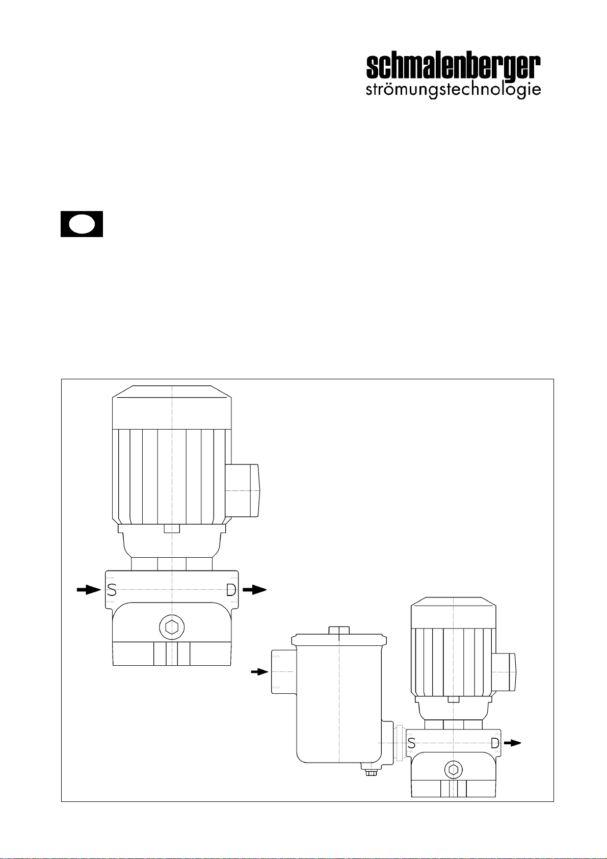
Pump type S / SF
Version: 27229 - E
When installed on a foundation the centrifugal
pump must be set up with the aid of a spirit level.
2.3.4 Connecting the pipework
Note the denomination on the housing:
S = suction connection, D = pressure
connection
The pipes must be supported as close as
possible to the centrifugal pump and connected
to it free of all tension. Their weight must not be
supported by the pump.
The positioning must be undertaken with the
greatest care as this is the prerequisite for
trouble-free operation of the plant.
If these instructions are not observed,
then any claims under guarantee will be
void.
• If the pipe strength is exceeded leaks can
occur in the pump or in the flange
connections, for example, that could result in
vast amounts of medium being expelled.
• In the case of short pipes the nominal bore
should be at least the same as the
centrifugal pump connections. For long
pipes the most economic nominal bore
should be determined on a case by case
basis.
• Connection pieces to larger nominal bores
should be carried out with approx. 8°
expansion angle to avoid significant loss of
pressure.
• In order to prevent the formation of air
pockets, the suction pipe to the centrifugal
pump must be installed to rise continuously,
on the pressure side it must fall continuously.
Depending on the type of system and
centrifugal pump being used, it is
recommended that backflow prevention and
shut-off devices are installed.
• Often welding beads, scales and other
impurities do not get dislodged for some
period of time. They should be kept clear of
the pump by inserting a sieve in the suction
pipe.
• The free cross-section of the sieve must be
3 times the cross-section of the pipe so that
there is not too large a resistance built up
due to foreign bodies that flow in.
Hat-shaped sieves containing a mesh wire net
having a mesh size of 2.0 mm and
0.5 mm wire diameter made of corrosion
resistant material have proved useful in practice.
2.3.5 Electrical connections
The electrical connections to the pump must be
carried out by a specialised company in the
electrical engineering branch approved by the
local energy provider, taking into account the
technical connection requirements.
Positioning them with the
motor hanging downwards is
not permitted.
Warning!
Under no circumstances must
the pump be used as anchor
point for the pipework. No
forces or moments (e.g. due to
twisting or heat expansion)
from the pipework must act on
the pump.
Important
Pipe compensators must not be
used to make up for inaccuracies in
the pipelines, for example with a
centre offset of the flange.
Warning!
In the case of hot, caustic or
poisonous delivery media!
Warning! Mortal danger!
Taps that close very suddenly
(abruptly) must be avoided in the
pipework. The resulting pressure
surges can greatly exceed the
maximum permitted housing
pressure of the pump!
To prevent too strong pressure
surges dampers or blast tanks
should be installed.
Note:
At the end of installation, before
starting up the system the tanks,
pipes and connections must be
thoroughly cleaned, rinsed and
blown through.

10 Schmalenberger GmbH + Co. KG
D-72072 Tübingen / Germany Pump type S / SF
Version: 27229 - E
The connections must be carried out by a
qualified electrician. (see chapter 2.3.1)
The relevant DIN VDE (Association of
German Engineers) regulations must be
observed.
Compare the available mains voltage with the
details on the motor’s factory plate and select the
appropriate switching.
We recommend the use of a motor protection
facility.
In compliance with VDE 0530-8, three-phase
motors are always wired for clockwise rotation
(looking at the motor shaft stub).
The direction of rotation of the pump is anti-
clockwise as standard (viewed from the suction
flange).
Always note the arrow on the pump
indicating the direction of rotation.
Connect the motor according to the circuit
diagram in fig. 1 or fig. 2.
Delta connection lower voltage)
Fig. 1 Connection diagram for 3-phase motors,
Circuit arrangement
Star connection Y (high voltage)
Fig. 2 Connection diagram for 3-phase motors,
Circuit arrangement Y
Motor with PTC thermistors as thermal win-
ding protection
Connect the PTC thermistor (PTC sensor) to the
downstream trigger unit if required. The PTC
thermistors are designed according to DIN
44081 and DIN 44082.
Time relay setting
For three-phase motors with star-delta
connection it must be ensured that the switching
points between star and delta follow each other
very rapidly. Long switching times can result in
damage to the motor. Setting of the time relay for
star-delta connection: < 3 sec.
Direction of rotation check
The direction of rotation of the motor must agree
with the direction of the rotation arrow on the
motor housing of the pump. Check by rapidly
switching on and off.
If the direction of rotation is wrong, change any
two phases L1, L2 or L3 of the power supply in
the motor terminal box over.
Additional motor equipment
If particular control devices are to be used e.g. in
connection with the installation of the pump in a
process engineering facility, the instructions of
the manufacturer of the control device must be
strictly observed.
3 Pump operation
3.1 Initial start-up
1. The centrifugal pump has been connected
properly electrically and with all requisite
safety features.
2. If the pump is supplied with an inflow of
medium, i.e. on the suction side the medium
is above the level of the pump, then the
suction and pressure shut-off devices must
be open and the pump must be primed.
Risk of explosion!
Where there is a risk of explosion a
motor protection device must be
fitted!
W2 U2 V2
U1 V1 W1
L2 L1 L3
W2 U2
U1 V1 W1
L2 L1 L3
V2
Prior to initially starting up the
centrifugal pump please make sure
that the following prerequisites
have been met:

Schmalenberger GmbH + Co. KG
D-72072 Tübingen / Germany 11
Pump type S / SF
Version: 27229 - E
3. If the pump is used to deliver medium
through suction, i.e. on the suction side the
medium is below the level of the pump, then
a foot-operated valve must be installed at the
lowest point of the suction pipe and the
pump and suction pipe must be filled with
fluid.
Please observe: Dry running leads to
increased wear and damage to the pump!
4. The rotating parts of the pump have been
covered by a protective shield. (In
accordance with UVV (Accident Prevention
Regulations) the centrifugal pump may only
be operated if a safety shield has been
fitted).
5. It has been checked that the pump shaft
rotates easily.
6. The direction of rotation has been checked.
3.1.1 Starting the pump
Start the pump only with the pressure pipe half-
open! Only after the maximum rotation speed
has been reached, slowly open the shut-off
device and adjust to full operational level.
Warning! Do not overload the motor!
• An automatic backflow prevention device
must constantly open once the operational
value has been reached without the
production of abnormal noises, vibrations or
increased current consumption in the plant.
• Once the operating point has been reached,
the power input to the motor and the bearing
temperature must be monitored!
When first started up the ultimate bearing
temperature is attained only after about 48
hours, depending on ambient conditions.
3.2 Operating
3.2.1 Operation monitoring
In most cases the centrifugal pump is controlled
from the central point of the overall facility. A
prerequisite for a perfectly functioning centrifugal
pump is adherence to the data provided for its
installation and use. See the chapter on
specifications.
1. Temperature of the delivery fluid
Never operate the pump at temperatures in
excess of those stated in the original
specification.
2. Noise emission
The acoustic power or sound pressure level is
determined by the motor as well as the pump,
and especially by the installation situation.
Special protective measures must be taken to
reduce transmission of structure-borne or air-
borne sound.
3. Switching frequency
In order to avoid a large temperature increase in
the motor and excessive strain on the pump,
motor and bearings the switching frequency
must not exceed the following guideline figures.
4. Minimum amount
If the sort of facility includes the possibility of a
run against closed shut-off device on the
pressure-end, a minimum delivery rate at t -30 to
+70°C 15% of Qopt. must be supplied during this
time. Over +70 to +110°C it must be 25% of
Qopt.
5. Density of the delivery fluid
The power input of the pump changes in
proportion to the density of the delivery fluid. To
prevent the motor being overloaded, the density
must correspond to the data in the specifications.
Pay particular attention to the
following points for the manual
operation of the centrifugal pump:
Motor power: Max. no. switches / h
up to 3 kW 20
from 4 to 11 kW 15

12 Schmalenberger GmbH + Co. KG
D-72072 Tübingen / Germany Pump type S / SF
Version: 27229 - E
6. Mechanical seal
The sealing unit has been fitted and set at the
factory. The gasket is maintenance free but
should be checked for leaks from time to time.
During initial start up there may be increased
leakage for a brief time. If increased leakage
persists then the plant should be switched off at
once and the cause determined. The cause
could be dirty medium or a prior period of dry
running through incomplete venting of the pump,
for example.
3.2.2 Miscellaneous
Installed reserve pumps must be run briefly once
a week to ensure that they are always ready for
operation. They should be run each time for
approx. 15 minutes. This also applies to any
pump that is not in use but must remain ready for
operation.
3.3 Indications of faulty operation
3.3.1 General
When operated via a central control facility faulty
operation can be largely ruled out.
In the case of manual operation, but also within
a control complex, please make sure that:
• The pump always runs quietly and vibration
free.
• The pump does not run dry.
• A longer period of operation with closed
shut-off device is avoided to prevent heating
up the delivery medium. For the requisite
minimum delivery quantity see chapter 3.2.1
Operation monitoring.
• The maximum permitted room temperature
of +40°C is not exceeded.
• The ball bearing temperature does not
exceed the room temperature by more than
+ 50ºC and in any event does not exceed +
90ºC overall (measured at the exterior of the
motor housing).
• During centrifugal pump operation the shut-
off device in the supply line is not closed.
3.3.2 Faults
In case of faults in the operation of the centrifugal
pump, that were not caused by the control facility
or other foreign devices, proceed as follows:
1. Locate the site of the fault or defect.
2. Determine the cause.
3. Remedy the fault.
In chapter 3.5 Fault elimination there is a table
listing the most frequent faults, their cause and
the recommended way to eliminate them.
3.4 Shutdown
1. Close shut-off device in the pressure and
suction pipes. If backflow prevention is fitted
to the pressure pipe the shut-off device can
remain open, provided that there is back
pressure.
2. Switch motor off. Allow it to come to rest.
Depending on the sort of facility, the pump
should be allowed sufficient idle run time –
with the heat source, if any, switched off to
allowthe delivery fluid temperature to reduce
– to prevent an accumulation of heat within
the pump.
3. Close the shut-off device in the suction pipe.
Warning! Risk of damage!
If there is a danger that the pump
may freeze and / or for occasions
where it is to be at a standstill for
longer periods of time, the pump
must be emptied or protected
against freezing up (by auxiliary
heating).

Schmalenberger GmbH + Co. KG
D-72072 Tübingen / Germany 13
Pump type S / SF
Version: 27229 - E
3.5 Fault elimination
Pump stationary
Pump delivery rate too low
Motor overload
Excessive pump pressure
Increased motor / bearing temperature
Pump leaks
Pump runs noisily, operating noises
Pump temperature too high
Cause of the fault Elimination of the fault
xPump has to work against too high a
pressure Readjust operating point
xBack pressure too high System contaminated,
reduce space between distributor and
open impeller,
install a new impeller (*)
xxx
Pump / pipework not completely vented Vent and fill with fluid
xSupply or impeller blocked Eliminate the cause in pipework or
pump
xAir pockets in the pipework Change pipework, install venting valve
xxx
Suction height too great / NPSH too low
(supply) Correct fluid level / level control, install
pump lower down, fully open valves in
the suction pipe, decrease resistance in
the supply pipe, clean sieves and
suction connections
xNon-return valve does not open Check non-return valve
xxx
Wrong direction of rotation Change over 2 phases in the terminal
box
xSpeed of rotation too low Increase the rpm (*), observe circuit
diagram (if necessary, new motor)
xxx
Worn internal parts (e.g. the impeller),
foreign body in the pump Remove foreign bodies from the pump
housing, replace worn parts
xx
Pump back-pressure is less than stated
in the specifications Set operating point precisely, increase
counter-pressure by throttling, turn off
impeller if required (*), use larger motor
(*)
xx Higher density or higher viscosity of the
delivery medium than specified (*) (Re-adjust the pump )
xShaft gasket worn or sealing ring
defective, gasket old, dry running Replace shaft gasket, change gasket,
check installation and assembly
dimensions
xx Motor wrongly connected Check circuit diagram, see chapter 2.3.5

14 Schmalenberger GmbH + Co. KG
D-72072 Tübingen / Germany Pump type S / SF
Version: 27229 - E
(*) Please consult the manufacturer.
xxx Pump wrongly adjusted Adjust pump properly
xxx Pump distorted or resonance vibrations
in the pipework Check pump holder, individual
installation
xx Bearing defective, too little or too much
or the wrong lubricant Replace bearing, add or reduce or
completely replace lubricant
xCoupling distance not observed Set distance properly
xx Motor runs on 2 phases Check / repair fuse and conductor
connections
xx Impeller out of balance Clean impeller, balance impeller (*)
xForeign body in the pump, motor
bearings defective Remove foreign bodies, clean or replace
pump housing, renew motor bearings
xCircuit breaker tripped due to motor
overload, circuit breaker too small,
winding defective
Check electrical connection (compare
with motor rating plate), if the motor is
overloaded: Throttle the pump, smaller
impeller (*), larger motor (*) or replace
stator (*)
xx
High level of air content in medium De-gas the delivery medium
xCavitation Throttle pump on pressure side
xxxx Impeller loose, clamping pieces loose Tighten clamping pieces with impeller
nut / screw (observe impeller gap)
xImpeller does not press enough on
mechanical seal Check installation / assembly
dimensions
Pump stationary
Pump delivery rate too low
Motor overload
Excessive pump pressure
Increased motor / bearing temperature
Pump leaks
Pump runs noisily, operating noises
Pump temperature too high
Cause of the fault Elimination of the fault

Schmalenberger GmbH + Co. KG
D-72072 Tübingen / Germany 15
Pump type S / SF
Version: 27229 - E
4 Maintenance / Repair
General Instructions
The operator must ensure that all maintenance,
service and repair work on the pump is carried
out exclusively by authorised and specially
trained persons. It must be established beyond
doubt that the person has studied the operator’s
manual in detail.
Werecommend the creation of andadherence to
a maintenance schedule. That will enable you to
avoid expensive repairs and have a reliable and
trouble-free pump operation.
Only original spare parts must be used for
repairs. This is particularly important for the
mechanical seal (GLRD ).
If work has to be carried out on the motor the
instructions in the manual from the relevant
motor manufacturer must be observed.
4.1 Maintenance / Service
Use the following information to create a
maintenance schedule. These are
recommendations of minimum requirements that
must be adjusted to local conditions of use of the
pump and may need amending accordingly.
4.1.1 Checks
Continuous checks:
• Centrifugal pump delivery data (pressure,
amount)
• Power take-up
Daily checks:
• Pump running is quiet and vibration free
• Bearing temperature
• Leakage at the mechanical seal (GLRD )
More frequent monitoring must be planned for
liquids with properties that differ greatly from
those of water (which tend to stick or form
accumulations, for example, or have a high gas
content).
Smooth operation of the shaft may be impaired
for example by accumulations on the mechanical
seal or if the mechanical seal sticks. If this
happens, smooth operation must be restored
before starting up. See section 5.1.3 "Restarting
after Periods of storage".
4.1.2 Lubrication and changing
lubricant
Centrifugal pumps type "S" in the standard
models only run on bearings in the drive motors.
The bearings in small motors are designed to
last the useful life of the motor and are filled with
a grease that cannot be replenished. In this case
there are no lubrication nipples on the bearing
supports.
4.2 Repair
General
Always carry out repair work on the removed
centrifugal pump in an appropriate workshop.
Make sure that you observe the safety
instructions in the chap. 1!
The following instructions will enable you to
dismantle the pump and to re-assemble it
properly with the requisite spare parts in place.
When a new mechanical seal is fitted special
instructions must be observed.
The work can be undertaken with the usual
workshop tools. No special tools are needed.
After dismantling thoroughly clean all the
individual parts of the centrifugal pump.
Warning! Mortal danger!
In order to prevent electric shocks,
work on the terminal box and the
machine controller must never be
carried out before the electrical
connections have been isolated or
disconnected.
Warning!
Risk of injury and mortal
danger!
The pump must be safeguarded
against unintentional switching on
(be disconnected) if checking or
maintenance work is to be
undertaken.
Note:
Please also observe the drawing in
the chapter “Spare parts / drawing”
at the end of this operator’s
manual!

16 Schmalenberger GmbH + Co. KG
D-72072 Tübingen / Germany Pump type S / SF
Version: 27229 - E
Check the individual parts for wear and damage.
Parts that are not perfect must be reworked or
replaced.
4.2.1 Dismantling Preparations
Prior to starting to dismantle it the pump must be
safeguarded against accidental switching on
(it must be disconnected).
When used in a facility, inform the shift leader or
manager.
4.2.2 Dismantling / Removal of the
pump
The pump must be allowed to reach room
temperature.
• Disconnect the power supply.
• Close valves (on the suction and pressure
sides).
• Empty the pump via the drainage screw 912.
• Disconnect motor.
• Remove existing additional connections.
• Release pressure and suction connections.
• If necessary, loosen the pump from the base
plate and remove entirely.
1. If the pump was used to deliver liquids that
are hazardous to health, then great care
must be taken in emptying the pump that
neither persons nor the environment are
placed at risk through the process.
2. If necessary, wear protective clothing and
protective mask!
3. The rinsing liquid used and any residual fluid
out of the pump must be caught and
disposed of properly and without placing
persons or the environment in any danger.
4. Pumps that deliver liquids that are
hazardous to health must be
decontaminated. In draining the delivery
medium off care must be taken that neither
persons nor the environment are placed in
any danger.
5. Legal requirements must be adhered to!
4.2.3 Dismantling / Dismantling the
pump
Before you begin:
Begin the work only once you have checked that:
• The required spare parts are available and
that they will fit this pump or your particular
model thereof. Or that the suspected
damaged parts can be obtained promptly.
Make sure that the position number is stated
in your spare parts order.
• You have all the required tools and
accessories for the work.
Observing these instructions is a prerequisite for
trouble-free operation of the pump and for the
acceptance of potential claims under guarantee.
4.2.4 Dismantling the pump (from the
suction side)
Place the pump on its blower cover and secure
against tipping over.
1st step:
Loosen the mounting screws 901/914 on the
cover 160 and remove the cover. Remove clamp
gasket 400 between cover and pump housing
101.
Warning! Mortal danger!
Fasten a warning on the switching
cabinet.
Important:
For the following work, please be
sure to observe local regulations
and conditions.
Warning!
When emptying the centrifugal
pump please observe the following
instructions!
Note:
Use only original sp3are parts for
the repairs!
All the gaskets must be replaced
when the pump is re-installed.
Customer service:
Schmalenberger provides a 24
hour service for the delivery of
spare parts!

Schmalenberger GmbH + Co. KG
D-72072 Tübingen / Germany 17
Pump type S / SF
Version: 27229 - E
2nd step:
Loosen the impeller nut 922 or impeller screw
906 and screw it off the motor shaft 819.
Pull off impeller 233 including clamping pieces
859 and distance washers 525 from the motor
shaft 819.
-> Remember the sequence of events for re-
assembly!
3rd step:
If fitted, remove retaining ring 932. Pull off
washer 550.02 or bush 525.02 from the shaft.
4th step:
Loosen screw 901/902 and, if necessary, nut
920.
4.2.5 Removalofthemechanicalseal
(GLRD )
Carefully pull pump housing 101 with GLRD 433
off the shaft.
Make sure that the shaft and GLRD are not
damaged during removal.
The mechanical seals used in the centrifugal
pumps are not free of wear. When dismantling
the pump check the mechanical seals for
damage. Damaged mechanical seals must be
completely replaced.
4.2.6 Bearing pedestal (S-L)
If your pump is equipped with an IEC Norm
motor as drive, then there is a bearing pedestal
for supporting the pump shaft and the coupling
between the pump and the motor.
The bearings are enclosed and provided with
grease that cannot be replenished. The coupling
is designed to last for the service life of the motor
under normal operating conditions.
To replace the coupling or one of the bearings,
proceed as follows:
• Loosen the drive from the bearing pedestal.
Remove the motor with the upper half of the
coupling.
Now you can replace the inner coupling part.
• To replace the ball bearings the pump must
be removed and dismantled as described in
chapter 4.2.4 .
• Remove the locking rings from the shaft and
out of the bearing pedestal. Take out the ball
bearings.
4.2.7 Pump re-installation
In principle the re-installation is in the reverse
order of dismantling.
Please observe by way of preparation:
• Thoroughly clean all the individual parts of
all dirt.
• Check all parts for wear. Damaged parts
must be replaced by new ones.
• Clamp gaskets and O-rings must always be
replaced by new ones. Grease O-rings prior
to installation.
Exception:Do not grease O-rings on theGLRD.
See the special instructions for installing the
GLRD.
• When fitting the screw connections always
tighten alternately cross-wise.
Use a torque wrench for this.
The following table shows the torque to be
applied for standard DIN 13 thread.
The figures apply to new, ungreased screws.
The table values do not apply if deviating values
are specified on the general diagrams or due to
other instructions.
4.2.8 GLRD installation
Preparation:
Increased cleanliness must be observed in the
immediate area where the GLRD installation is
to take place.
Accessories:
- Propyl alcohol and cellulose cloths (no
cleaning rags!)
- O-ring lifter
- Water and detergent
Thread:
Torque [Nm] for screws:
to plastic
parts to cast parts to bright
steel parts
M8 7 10 - 15 20
M10 8 25 - 35 40
M12 10 30 - 40 70
M16 -- 60 - 90 160
M20 -- 80 - 110 --

18 Schmalenberger GmbH + Co. KG
D-72072 Tübingen / Germany Pump type S / SF
Version: 27229 - E
Work steps:
• Unpack the GLRD and check for any
damage.
• Thoroughly clean all sliding surfaces with
propyl alcohol and cellulose cloths.
• In the case of GLRD with elastomer coating,
to avoid friction when fitting the gasket,
bellows and shaft should be moistened with
water whose surface tension has been
reduced by the addition of detergent, for
example
• Cover the sliding surface with a cardboard
disc.
• Press the counter-ring slowly and steadily
into the holding seat.
• Check that the counter-ring is seated at
right-angles to the shaft axis.
• Clean the sliding surfaces to be striation free
with propyl alcohol and cellulose cloths.
Push the rotating unit (bellows unit, sliding
ring) onto the shaft by turning gently
clockwise until the sliding ring lies against the
counter-ring.
Installation of the mechanical seal
You can order suitable guide bushes from
Schmalenberger GmbH & Co. KG.
• Check that the thrust collar (spring collar),
spring and sliding ring sit tightly.
Then continue with the assembly of the pump by
fitting the impeller.
Observe the clearance in the gap on the
impeller.
We recommend that you use our device for
setting the gap clearance.
4.3 Spare parts list / Drawing
On pages 20 - 24 there are the spare parts list
and the drawing of your pump.
Please take note of your pump type and the
relevant model.
5 Appendix
5.1 Shutdown / Storage /
Conservation
Every pump leaves the factory carefully
assembled. If initial operation is predicted to be a
long time after delivery we recommend the
following measures for storage of the centrifugal
pump.
5.1.1 Storage of New Pumps
When requested, new pumps receive a
conservation protection corresponding to the
storage time stated by the purchaser.
If this period of time is considerably exceeded
the condition of the pump must be checked and,
if required, re-conserved.
Warning! Risk of damage!
Never place sliding rings or their
counterparts onto the plane of
sliding without using a protective
cover.
Warning!
Under no circumstances must oil or
grease be used to assist with the
assembly!
Important:
Do not touch the sliding
surfaces with bare hands.
Important:
Use a suitable guide bush to push
the GLRD over the keyways, etc.
without damaging it.

Schmalenberger GmbH + Co. KG
D-72072 Tübingen / Germany 19
Pump type S / SF
Version: 27229 - E
5.1.2 Long Periods of Shutdown
> 3 months
1. Pump remains installed
To ensure that the pump is always ready for
operation and to prevent the formation of
deposits inside the pump and in its immediate
vicinity, the pump aggregate should be run for a
short time (approx. 15 minutes) monthly or
quarterly during longer periods of inactivity.
Prerequisite for this is that sufficient fluid is
supplied to the pump.
2. Pump is removed and stored
To remove the pump proceed as outlined in
chapter . 4 Maintenance / Repair .
Prior to storing the pump it must be thoroughly
cleaned and conserved. Conservation must be
done both internally and externally.
5.1.3 Restarting after Periods of
Storage
De-conservation
Before the stored pump is re-installed the
conservation agent (covering or filling) must be
removed.
Proceed as described in chapter 2.2.2 Cleaning.
Restarting
Re-install the pump according to the procedure
described in chapter 2.3 Installing and
connecting.
Immediately after completing the above work, all
safety and protective measures must be properly
installed and checked that they function.
Before the pump is re-started the checks and
maintenance measures stated in chapter 4.1
Maintenance / Service must be carried out.
For the new re-start the points listed in section
3.1 Initial start-up must also be observed.
Particularities of the mechanical seal:
Prior to an initial start-up and after longer periods
of standstill or after a new mechanical seal is
installed it is important to check that the pump
runs freely.
The sliding ring and its counterpart ring can stick
together very firmly due to adhesive forces. The
force of the driving spring is then not enough to
break the sliding ring away.
In this case the shaft runs in the static seals and
the driving spring, which leads to damage.
Remove the blower cover and turn the blower
wheel in the direction of the arrow. If there is
resistance and the blower wheel feathers back
then the mechanical seal has to be removed and
the sliding ring and its counterpart ring must be
carefully separated.
Under no circumstances should the shaft
be turned by force.
5.2 Disposal
If you want to take the pump completely out of
service and never re-use it then please observe
the local regulations for the disposal of industrial
waste.
Warning!
After long periods of storage under
conservation conditions check the
shape stability and elasticity of the
Elastomers (O-rings and
mechanical seals). Brittle rings
must be replaced. Elastomers
made of EPDM should be replaced
in any event.
Warning! Mortal danger /
poison!
Pumps that have delivered
poisonous, caustic or other
chemical substances which are a
danger to people and the
environment must be thoroughly
cleaned and / or decontaminated
prior to being disposed of.
The cleaning agents and rests of
the delivery medium must also be
handled in accordance with legal
requirements.
If such legal regulations exist in the
area where the pump is operated
then the pump must be completely
dismantled and sorted into the
different materials so that they can
be disposed of separately.

20 Schmalenberger GmbH + Co. KG
D-72072 Tübingen / Germany Pump type S / SF
Version: 27229 - E
5.3 Supporting documents for
pump operation
The following documents are enclosed:
- Operator’s manual
- Dimensional sketch
In case of complaints regarding the pump motor,
please contact us or the motor manufacturer.
5.4 Data sheet
The enclosed data sheet corresponds to the
pump supplied.
You are not allowed to change the dimensions of
the pump.
Please also be sure to observe the other
documentation referred to in these operating
instructions, see chapter 1.2 !
5.5 Important Instructions
5.5.1 Factory repair
Please observe the following instructions if the
pump is sent back to the factory for repair:
1. If you send the pump back to the
manufacturer for repair or an upgrade then
please be sure to enclose precise details of
the media that were delivered by the pump.
3. Only pumps that are completely empty and
clean will be accepted for repair.
5.5.2 Ordering Spare Parts
When ordering spare parts please do not fail to
give us the following important information:
• Pump serial number and type description or
alternatively the motor serial number
• Delivery medium
• Part number from the spare parts list
• Part description
• Material data from the specifications or the
order confirmation
The pump serial number is on the type plate
which is fastened to the blower cover of the
motor.
The order confirmation or motor serial number
may also be of assistance.
With this information you make it much easier for
us to deliver the correct spare part for your
pump!
Customer service
Schmalenberger provides a 24 hour service for
the delivery of spare parts!
See our homepage under:
www.schmalenberger.de
Head office address:
Schmalenberger GmbH & Co. KG
Im Schelmen 9 - 11
D-72072 Tübingen
Telephone:+ 49 (0) 7071 - 7008-0
Fax: + 49 (0) 7071 - 7008-14
6Spare parts list and drawings
Important:
If changes have subsequently
been made to the pump supplied
then any claims under the
guarantee will be void.
Warning!
2. If the delivered media were
poisonous, caustic, etc. then
please be sure to enclose a
copy of the safety sheet for the
media! In the spare parts list (page 21)
all parts of the pump types are
listed.
Not all parts are built into every
pump, however.
This manual suits for next models
2
Table of contents
Other schmalenberger Water Pump manuals

schmalenberger
schmalenberger ZHT User manual

schmalenberger
schmalenberger fluvo C2 rondo User manual

schmalenberger
schmalenberger FLUVO NB User manual

schmalenberger
schmalenberger FZ Series User manual

schmalenberger
schmalenberger KSP 3208 Series User manual

schmalenberger
schmalenberger Fluvo WK Series Product guide
Popular Water Pump manuals by other brands

Cornell
Cornell 6NHTA Installation, operation and maintenance manual

Wilo
Wilo Medana PE3 Series Installation and operating instructions

RVR Solar
RVR Solar Closet 300 PS Installation, Usage and Maintenance Instructions

Espa
Espa TIPER0 instruction manual

PIAB
PIAB Lab Vac LVH40 manual

Anest Iwata
Anest Iwata IS800 Operating instructions manual