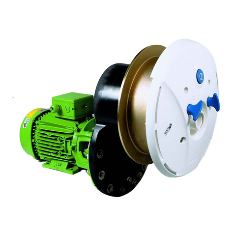
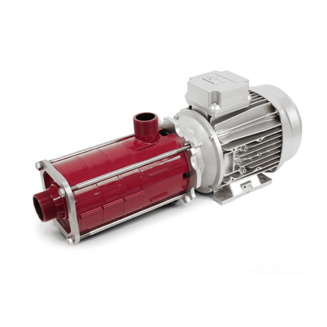
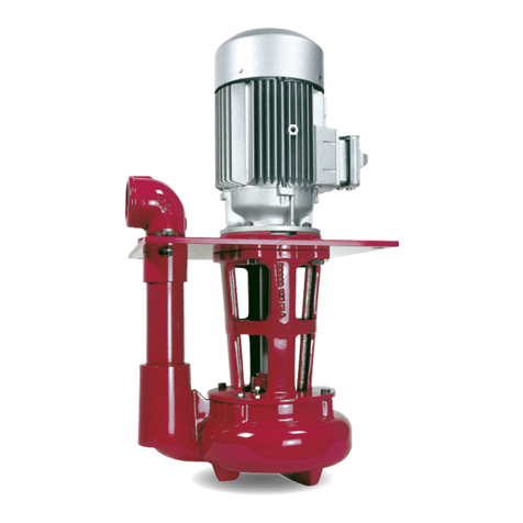
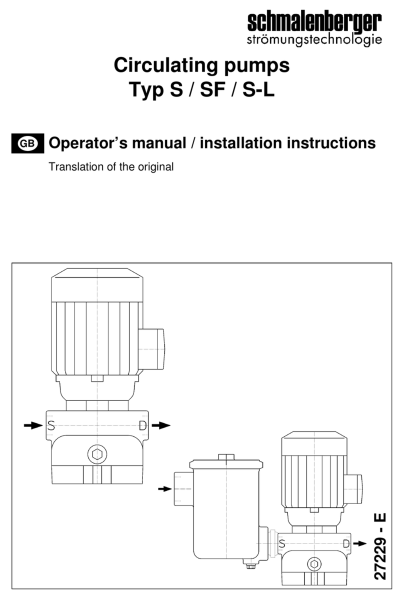
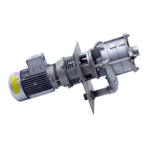
schmalenberger FLUVO NB User manual

Typ Optimo 150
27216 - E
WP F
SM NB
Optimo F
FB
Operators manual / installation instructions
Translation of the original
GB
Centrifugal pump
Type NB / FB / WP / SM / F

2 Pump NB/FB/WP/SM/F
Version: 27216 - E
Schmalenberger GmbH + Co. KG
D-72072 Tübingen / Germany
EU Declaration of Conformity
Manufacturer:
Schmalenberger GmbH + Co. KG
Strömungstechnologie
Im Schelmen 9-11
D-72072 Tübingen / Germany
The manufacturer hereby declares that the product:
Centrifugal pump type:
NB, FB, SM, WP, NBB, NBL, FBL, FBB, SML, SMS, WPL, WPB, F, Optimo-F (identification numbers: all)
Serial number range: 2018000001 - 2023999999
has been manufactured in accordance with the following directives:
Directive 2006/42/EC "Machinery"
The machine continues to comply with the provisions of the directives:
2014/34/EU - applies only to products with ATEX marking: 2G, 3G, 2D or 3D on the pump rating plate.
Standards that were used: EN 80079-36, EN 80079-37
Harmonised standards that were used:
EN 809+A1+AC, EN ISO 12100, EN 60034-1, EN 60034-5/A1, EN 60034-30-1
Authorised representative for the compilation of the technical documentation:
Marco Alber
Quality assurance
Schmalenberger GmbH + Co. KG
D-72072 Tübingen / Germany
Phone +49 (0)7071 7008-18
The EU Declaration of Conformity has been issued:
Tübingen, 10. April 2018
----------------------------------------------
Thomas Merkle
Head of Development & Design
Schmalenberger GmbH + Co. KG

3
Pump NB/FB/WP/SM/F
Version: 27216 - E Schmalenberger GmbH + Co. KG
D-72072 Tübingen / Germany
EU Declaration of Incorporation
Manufacturer:
Schmalenberger GmbH + Co. KG
Strömungstechnologie
Im Schelmen 9-11
D-72072 Tübingen / Germany
The manufacturer hereby declares that the product:
Centrifugal pump if delivered without drive, type:
NBB, NBL, FBB, FBL, WPL, WPB, SMS, SML (identification numbers: all)
Serial number range: 2018000001 - 2023999999
an incomplete machine in accordance with Regulation 2006/42/EC Article 2g and provided exclusively for
assembly with another machine
which meets the following basic requirements of Regulation 2006/42/EC:
Appendix I, Article 1.1.1, 1.1.2, 1.1.3, 1.1.5.
Harmonised standards that were used: EN 809+A1+AC, EN ISO 12100
The machine continues to comply with the provisions of the directives:
2014/34/EU - applies only to products with ATEX mark 3G or 3D on the pump rating plate.
Standards that were used: EN 80079-36, EN 80079-37
The incomplete machine must not be placed in operation until it has been determined that the machine to be
installed in the incomplete machine is in compliance with the requirements of the Machinery Directive (2006/
42/EC).
Authorised representative for the compilation of the technical documentation:
Marco Alber
Quality assurance
Schmalenberger GmbH + Co. KG
D-72072 Tübingen / Germany
Phone +49 (0)7071 7008-18
The EU Declaration of Incorporation has been issued:
Tübingen, den 10. April 2018
----------------------------------------------
Thomas Merkle
Head of Development & Design
Schmalenberger GmbH + Co. KG

4 Pump NB/FB/WP/SM/F
Version: 27216 - E
Schmalenberger GmbH + Co. KG
D-72072 Tübingen / Germany
Table of contents
1 General Information .......................................................................... 6
1.1 User Information ..............................................................................................................6
1.2 Proper Use ......................................................................................................................6
1.3 Other Applicable Documents ...........................................................................................7
1.4 Technical Data Specification........................................................................................... 7
1.5 Safety Instructions ...........................................................................................................7
1.6 Temperature ....................................................................................................................8
1.7 Safety Instructions for Maintenance, Inspections, and Repair work ................................8
2 Transport, Storage and Assembly .................................................. 9
2.1 Transport and Storage ....................................................................................................9
2.1.1 Transport .........................................................................................................................9
2.1.2 Storage ............................................................................................................................9
2.1.3 Preservation ..................................................................................................................10
2.2 Unpacking, Cleaning and Assembly ..............................................................................10
2.2.1 Unpacking .....................................................................................................................10
2.2.2 Cleaning ........................................................................................................................10
2.2.3 Assembly .......................................................................................................................10
2.3 Setting Up and Connecting ...........................................................................................11
2.3.1 Before starting to set up, check the following ................................................................11
2.3.2 Installation and Set-up of the Pump ..............................................................................11
2.3.3 Connecting the Pipelines ...............................................................................................12
2.3.4 Electrical Connection .....................................................................................................13
3 Pump Operation .............................................................................. 14
3.1 Initial Commissioning ....................................................................................................14
3.1.1 Starting the Pump ..........................................................................................................14
3.2 Operation .......................................................................................................................15
3.2.1 Operation Monitoring .....................................................................................................15
3.2.2 Other Requirements ......................................................................................................15
3.3 Notices of Incorrect Operation .......................................................................................16
3.3.1 General Information .......................................................................................................16
3.3.2 Faults .............................................................................................................................16
3.4 Shutdown ......................................................................................................................16
3.5 Troubleshooting............................................................................................................. 17
4 Maintenance / Repair ...................................................................... 19
4.1 Maintenance / Inspection ..............................................................................................19
4.1.1 Checks ..........................................................................................................................19
4.1.2 Lubrication and changing lubricant ................................................................................20
4.2 Repair ............................................................................................................................20
4.2.1 Preparations for Disassembly .......................................................................................20
4.2.2 Disassembly / Removal of the Pump ............................................................................21
4.2.3 Disassembly / Dismantling the Pump ............................................................................21
4.2.4 Dismantling the Pump ...................................................................................................22
4.2.5 Mechanical Seal (GLRD) ...............................................................................................23
4.2.6 Reassembling the Pump ...............................................................................................23

5
Pump NB/FB/WP/SM/F
Version: 27216 - E Schmalenberger GmbH + Co. KG
D-72072 Tübingen / Germany
5 Appendix ..........................................................................................26
5.1 Decommissioning / Placing in Storage / Preservation ...................................................26
5.1.1 Placing New Pumps in Storage .....................................................................................26
5.1.2 Extended Decommissioning > 3 Months .......................................................................26
5.1.3 Recommissioning after Being Placed in Storage ..........................................................26
5.2 Disposal .........................................................................................................................27
5.3 Documents for the pump drive ......................................................................................27
5.4 Dimension sheet ............................................................................................................28
5.5 Important Information ....................................................................................................28
5.5.1 Factory Repair ...............................................................................................................28
5.6 Spare Parts List / Drawing .............................................................................................28
5.6.1 Ordering Spare Parts ....................................................................................................28
6 Pumps with Norm Motors ...............................................................30
6.1 Disassembly (See illustration "Shaft assembly of bearing pedestal" in section "Spare
Parts") ............................................................................................................................30
6.2 Reassembly ...................................................................................................................31
7 Pumps with catchment chamber systems (SKS) .........................32
7.1 Other Applicable Documents .........................................................................................33
7.2 Usage Limits...................................................................................................................33
7.3 Improper Use .................................................................................................................34
7.4 Description of the Product .............................................................................................34
7.5 System with sealing pressure (SK) ...............................................................................34
7.6 System without sealing pressure (TLS) .........................................................................36
7.7 Sealing medium .............................................................................................................38
7.8 GLRD Materials .............................................................................................................38
7.9 Emissions, Personal Protection .....................................................................................38
7.10 Maintenance / Inspection ..............................................................................................39
7.11 Repairs ..........................................................................................................................40
7.12 Spare Parts ...................................................................................................................40
7.13 Removal and Reinstallation of GLRD (Mechanical Seal) ..............................................40
7.14 Copyright .......................................................................................................................40
8 Spare Parts ......................................................................................41
8.1 Type NB ........................................................................................................................41
8.2 Type FB .........................................................................................................................42
8.3 Type WP ........................................................................................................................43
8.4 Type F ...........................................................................................................................44
8.5 Type Optimo ..................................................................................................................45
8.6 Type SM ........................................................................................................................46
8.7 Shaft assembly of bearing pedestal ..............................................................................47
8.8 Type SKS /GLRD Tandem (TLS) ..................................................................................48
8.9 Type SKS / GLRD Back to Back (catchment chamber) ................................................49
8.10 Spare parts list ..............................................................................................................50

6 Pump NB/FB/WP/SM/F
Version: 27216 - E
Schmalenberger GmbH + Co. KG
D-72072 Tübingen / Germany
1 General Information
1.1 User Information
This Operator's Manual will make it easier for you to become familiar with the centrifugal
pump and make full use of its range of options.
It contains important information for operating the centrifugal pump safely, properly and
economically.
However, the Operator's Manual does not take into consideration requirements for a
specific location. The operator is responsible for observing these requirements.
The pump rating plate indicates the series and frame size, the most important operating
data and the factory number. Please specify this information if you have questions,
subsequent orders, or especially when ordering spare parts.
1.2 Proper Use
The centrifugal pump is intended exclusively for use in accordance with the original pump
specification and the Operator's Manual. Any other or more extensive use is considered
improper use. The manufacturer shall not be liable for any resulting damage.
The pump must only be operated in applications that are described in the relevant
documents.
• The pump must only be operated if it is in flawless technical condition.
• The pump must not be operated if it is only partially mounted.
• The pump may only be used to convey the media described in the data sheet or in the
documentation for the relevant design.
• Never operate the pump without a pumping medium.
• Pay careful attention to the information in the data sheet or documentation regarding
minimum delivery volume (to prevent damage from overheating, damage to the
bearings, etc.).
• Pay careful attention to the information in the data sheet or documentation regarding
maximum delivery volume (to prevent overheating, damage to the mechanical seal,
cavitation damage, damage to the bearings, etc.).
• Do not throttle the pump on the suction end (to prevent cavitation damage).
• Coordinate other types of operation with the manufacturer if they are not cited in the
documentation or data sheet.
Preventing foreseeable misuse
• Never open the pressure-end shut-off elements beyond the permissible range
- Exceeding the maximum delivery volume cited in the data sheet or documentation
is not permitted (possible cavitation damage)
• Never exceed the permissible operating limits cited in the data sheet or documentation
in terms of pressure and temperature, etc.
• Comply with all safety instructions and directions in this operator's manual.

7
Pump NB/FB/WP/SM/F
Version: 27216 - E Schmalenberger GmbH + Co. KG
D-72072 Tübingen / Germany
1.3 Other Applicable Documents
Each centrifugal pump has various documents which belong together with the Technical
Documentation for the centrifugal pump. They are:
The Operator's Manual for the centrifugal pump
The Operator's Manual for the drive
The Operator's Manual for the accessories listed in the specification
Acceptance reports from TÜV, etc.
Test run report
Performance run report
Assembly drawing (dimension sheet)
Supplementary Operator's Manual for ATEX pumps
Declaration of Conformity / Manufacturer’s Declaration
Specification with all information
Not all the documents named above exist or are included in every case. Observe the
information in the specification in this regard.
1.4 Technical Data Specification
The specification of the delivered centrifugal pump is the most important document for
every Operator's Manual. It contains a summary of all factual and technical data for the
centrifugal pump. It is the centrifugal pump's "birth certificate" and must be treated as such.
The confirmation of order together with the delivery slip can be used as a replacement as
proof of technical data.
1.5 Safety Instructions
Make certain the safety requirements and laws for the use of pumps which apply to the
operating company and/or country in which the system is operated are observed.
We warn you of sources of danger in this Operator's Manual through corresponding
notices. The use of symbols is designed to direct your attention at these notices.
Notices placed directly on the centrifugal pump, such as the arrow for direction of rotation
and identification of fluid connections, must always be observed. These notices must be
maintained in legible condition and replaced if necessary.
Caution - risk of injury!
This symbol warns you of dangers due to mechanical effects.
Caution - danger of death!
This symbol warns you of dangers due to electrical current.
Note!
This symbol warns you of actions that may damage or destroy the pump. It provides
information about financially efficient use of the pump.

8 Pump NB/FB/WP/SM/F
Version: 27216 - E
Schmalenberger GmbH + Co. KG
D-72072 Tübingen / Germany
• Use the centrifugal pump only when it is in flawless condition technically and according
to its intended purpose. Be conscious of safety and dangers and observe all the
instructions in this Operator’s Manual!
• Eliminate all malfunctions that could have a detrimental effect on safety immediately.
•Make certain before commissioning that the operating personnel have read and
understood the Operator's Manual. It is the owner rather than the operator who is
responsible for safety!
• The centrifugal pump is designed for installation in a complete machine or system. The
centrifugal pump is delivered without a contact safety device. If a contact safety device
is required (for example when pumping hot liquids above 60°C) it must be provided by
the system manufacturer when the centrifugal pump is installed in the system.
• If liquids are pumped that can cause effects detrimental to health in any way, suitable
measures must be taken (rinsing, cleaning, washing) to bring the wetted surfaces of
the pump to a condition to ensure that handling does not entail any dangers.
• Leaks of dangerous pumping media (for example explosive, toxic, hot) must be
diverted so there is no endangerment to persons or the environment. Legal
requirements must be observed.
• Hazards due to electrical energy must be excluded (for specific details, see country-
specific regulations and/or your local energy supply company).
• Work on the pump's electric equipment must only be performed by a professional
electrician or persons instructed by and under the direction and supervision of an
electrician in accordance with the electrical regulations of VDE or IEC.
• Before turning on the pump or placing it in operation, make certain no one can be
endangered by the pump starting up!
1.6 Temperature
1.7 Safety Instructions for Maintenance, Inspections, and Repair work
• Repairs of any nature must only be made by qualified professionals. The centrifugal
pump must be drained for this purpose.
• The connected pipelines must be depressurised.
• Allow the pump to cool off.
• Before making repairs to the pump, disconnect it from its electrical power source and
prevent it from being turned on again.
Important:
Stop the centrifugal pump immediately if any abnormal electrical voltages,
vibrations, temperatures, noises, leaks, or other faults occur.
Caution! Danger of burns!
The housing of the centrifugal pump heats up during operation! If the
temperature increases above + 50°C, the centrifugal pump must be protected
against direct contact by the operator.

9
Pump NB/FB/WP/SM/F
Version: 27216 - E Schmalenberger GmbH + Co. KG
D-72072 Tübingen / Germany
2 Transport, Storage and Assembly
2.1 Transport and Storage
2.1.1 Transport
Centrifugal pumps must be transported lying down! The lifting lugs on the motor are only
designed for the weight of the motor alone. A unit consisting of a motor and a pump unit
must be attached on both the motor and pump sides. If necessary, the position of the
centre of gravity is identified on the pump unit itself and on the packaging and the positions
for inserting lifting equipment are marked.
2.1.2 Storage
• Temporary storage
Even for temporary storage of short duration, store in a dry, well ventilated location free
of vibration on wooden supports at a temperature that is as constant as possible.
• Unsuitable storage
If storage conditions are unsuitable (for example high relative humidity), or if the pump
will be in storage for longer than 6 weeks, the pump housing must be filled with oil (see
2.1.3).
• Storage for extended duration
If the storage time exceeds 2 years, the roller bearings in the motor must be regreased
or completely replaced.
Risk of injury!
Use only suitable lifting equipment and load holding devices which are in
perfect working order and have adequate load-bearing capacity!
Never work or stand under suspended loads!
Fig. 1: Example of slinging for lifting

1 0 Pump NB/FB/WP/SM/F
Version: 27216 - E
Schmalenberger GmbH + Co. KG
D-72072 Tübingen / Germany
2.1.3 Preservation
The centrifugal pumps we deliver are provided with preservation according to the storage
time specified in the order. This preservation must be removed before commissioning; see
section 2.2.2 "Cleaning".
If the pump will be taken out of operation for an extended time or if the storage time
originally planned before commissioning will be considerably exceeded, preservation
should be performed as corrosion protection.
2.2 Unpacking, Cleaning and Assembly
2.2.1 Unpacking
The pump is secured on a pallet with bands for transport. For transport over extended
distances it is packed in cases or crates.
After the retaining bands are loosened, lift the pump out of the packaging with appropriate
auxiliary equipment (lifting tackle). Observe the instructions under 2.1.1 while doing so.
2.2.2 Cleaning
Various measures are provided for protection against transport damage or corrosion. Find
out which ones have been selected for your pump.
1. Cover plates on the connections
2. Shaft protection, for delivery without motor
3. Protective paint on bare metal parts
Before set-up or installation of the pump, these protective devices must be removed. No
contamination can be allowed to remain inside the pump.
2.2.3 Assembly
The pump generally comes premounted and is therefore ready for installation.
In special cases the pump is delivered without a drive motor. Connect the drive to the pump
before the pump is mounted in the system.
The procedure to follow is described in detail in section 5.1 „Decommissioning
/ Placing in Storage / Preservation“.
Note:
Depending on the pumping medium, the inside of the pump must be cleaned
of oil residue. Use a cleaning agent to do this that will not damage the
mechanical seal or the pump material. Make certain the pump is carefully dried
after cleaning.
Suitable cleaning agents include rectified spirits, Ritzol 155 or suds with a high
alkaline content. If steam jet cleaners are used, allow the solvent to act first.
If possible do not use steam jet cleaners. If you do, make certain not to damage
the electric motor and bearings during use.

11
Pump NB/FB/WP/SM/F
Version: 27216 - E Schmalenberger GmbH + Co. KG
D-72072 Tübingen / Germany
2.3 Setting Up and Connecting
2.3.1 Before starting to set up, check the following
• Is the machine / system / container connection prepared according to the dimensions
of the dimension sheet / installation diagram?
• Do the concrete foundations have sufficient concrete strength (min. B 15) per
DIN 1045?
• Is the concrete foundation hardened?
• Is the surface horizontal and even?
2.3.2 Installation and Set-up of the Pump
Except for the special design, pumps are always placed on a base plate with the pump,
bracket or motor mount and fastened with bolts.
For assembly on a foundation, the centrifugal pump must be aligned with a spirit level.
Pump with angle base
For installation on a foundation, the unit must be aligned using a spirit level on the pressure
connection.
Installation on motor mounts
Alignment as for angle base. For certain motor sizes, the motor mounts must be supported
underneath (see installation diagram).
Check to ensure the pump is running easily and freely before starting assembly
Other external accessories such as air chambers, etc., that are not
premounted on the pump in the factory should not be connected until after the
pump is installed in the system or on the pump foundation.
Explosion protection / safety instructions
Electrical equipment that will be operated in areas subject to the risk of
explosion must meet explosion protection requirements. These are identified
by the factory plate on the motor. For installation in areas subject to the danger
of explosion, applicable local regulations for explosion protection and
requirements of the test certificate included with delivery, which was issued by
the office responsible for testing, must be observed. The test certificate
included with delivery must be kept in a safe place at the installation location
(for example in the supervisor's office, etc.).
Stability - risk of injury!
Pump with large drives that are installed vertically are top-heavy. These pumps
must be secured against tipping during assembly or disassembly, for example
by using retaining ropes.
Caution!
Never install the pump with the
„motor below“.

1 2 Pump NB/FB/WP/SM/F
Version: 27216 - E
Schmalenberger GmbH + Co. KG
D-72072 Tübingen / Germany
2.3.3 Connecting the Pipelines
For short pipelines, the nominal widths should at least match those of the pump
connections. For longer pipelines, determine the most cost-effective nominal width from
case to case.
Transition pieces to larger nominal widths should be designed with an expansion angle of
about 8° to prevent increased pressure loss.
The suction line rises continuously to the pump. Lay pipelines continuously falling for the
supply to prevent air lock from forming.
Depending on the type of system and pump, installation of backflow prevention valves and
shut-off elements is recommended.
Expansion of pipelines due to temperature must be countered by suitable measures. We
recommend installing compensators in the pipeline.
Always avoid fittings in pipelines that close suddenly (rapidly). Pressure peaks which occur
as a result of these fittings may exceed the maximum permissible housing pressure of the
pump several times over! To avoid strong pressure peaks, install pressure absorbers or air
chambers.
Often welding beads, pipe scale and other impurities do not come loose until some time
has passed. They must be kept out of the pipe by installing a sieve in the suction line. The
open cross-section of the sieve must be at least three times the cross-section of the
pipeline to prevent too much resistance from building up due to trapped foreign objects.
Experience shows that hat-shaped sieves containing a mesh wire net with a mesh size of
2.0 mm and a wire diameter of 0.5 mm and made of corrosion resistant material are
effective.
The pump must never under any circumstances be used as a point for securing
the pipeline. No forces or moments (for example caused by warping or heat
expansion) from the pipelines may be allowed to affect the pump. Pipes must
be intercepted directly before the pump and connected with no tension.
Danger of death! When working with hot, corrosive ,and toxic pumping
media!
If pipeline forces are exceeded, points with faulty seals may develop on the
pump itself or on the flange connections, which may result in powerful ejection
of pumping medium.
Important
Pipe compensators must not be used to make up for inaccuracies in the
pipelines, for example with a centre offset of the flange.
After assembly is complete or before starting up the system, the containers,
pipelines and connections must be thoroughly cleaned, rinsed and blown out
with air.

13
Pump NB/FB/WP/SM/F
Version: 27216 - E Schmalenberger GmbH + Co. KG
D-72072 Tübingen / Germany
2.3.4 Electrical Connection
The electrical connection for the pump should only be made by a company specialising in
electrical systems that is approved by the power provider, taking into consideration the
technical connection requirements.
Connection tasks must only be performed by a certified installation electrician.
Applicable DIN VDE regulations must be observed.
Compare the existing mains power supply with the information on the factory plate of the
motor and select a suitable circuit.
We recommend using a motor protection device.
In compliance with VDE 0530-8, three-phase motors are always wired for clockwise
rotation (looking at the motor shaft stub).
The direction of rotation of the pump is anti-clockwise as standard (viewed from the suction
flange).
Always note the arrow on the pump indicating the direction of rotation.
Connect the motor according to the circuit diagram in fig. 2 or fig. 3.
Motor with PTC thermistors as thermal winding protection
Connect the PTC thermistor (PTC sensor) to the downstream trigger unit if required. The
PTC thermistors are designed according to DIN 44081 and DIN 44082.
Risk of explosion!
Motors with explosion protection must always be connected using a motor
protection switch.
Circuit (low voltage)
Fig. 2: Connection diagram for three-
phase motors, circuit
Circuit Y (high voltage)
Fig. 3: Connection diagram for three-
phase motors, circuit Y
W2 U2 V2
U1 V1 W1
L2 L1 L3
W2 U2
U1 V1 W1
L2 L1 L3
V2

1 4 Pump NB/FB/WP/SM/F
Version: 27216 - E
Schmalenberger GmbH + Co. KG
D-72072 Tübingen / Germany
Time Relay Setting
For three-phase motors with star-delta connection, you must ensure that the switching
points between star and delta follow one after the other in as little time as possible. Longer
switching times will result in damage to the motor. Time delay setting for star-delta
connection: < 3 sec.
Direction of Rotation Check
The direction of rotation of the motor must match the direction indicated by the direction of
rotation arrow on the hood of the pump. Check by switching on and off briefly.
If the direction of rotation is incorrect, reverse any two phases L1, L2 or L3 of the mains
power supply line in the motor terminal box.
Auxiliary Equipment for Motor
If special control devices are provided, for example in conjunction with use of the pump in
a technical system, the manufacturer's instructions for these control devices must always
be observed.
3 Pump Operation
3.1 Initial Commissioning
Make certain the following preconditions are met before initial commissioning of the pump:
• The pump is connected electrically with all protective devices in accordance with
requirements.
• The pump is filled with pumping medium and is receiving supply.
• All shut-off elements are open on the suction end and the suction line is vented.
•Make certain: Dry running results in increased wear and must always be avoided!
• Rotating parts of the pump must be provided with a contact safety device (in
accordance with German accident prevention requirements (UVV) the pump may only
be operated with a contact safety device).
• The pump shaft has been tested to ensure it moves easily
• The direction of motion has been checked.
3.1.1 Starting the Pump
The pump must only be turned on with the pressure-end shut-off element half open! Do not
open it until full speed is reached. Then slowly open it and adjust control to the operating
point.

15
Pump NB/FB/WP/SM/F
Version: 27216 - E Schmalenberger GmbH + Co. KG
D-72072 Tübingen / Germany
3.2 Operation
3.2.1 Operation Monitoring
In most cases the pump is controlled from the central control unit of the entire system. Data
associated with the design of the pump and related to the intended purpose (see
specification) must be observed as a precondition for problem-free functionality.
1. Temperature of the pumping liquid. -Do not operate the pump at temperatures
higher than those listed in the original specification.
2. Noise emission. - The acoustic power or sound pressure level is determined by the
motor as well as the pump, and especially by the installation situation. Special
protective measures must be taken to reduce transmission of structure-borne or air-
borne sound.
3. Switching frequency. - To avoid large temperature increases in the motor and
excessive load on the pump, motor and bearings, the permissible rate of one switching-
on process must not be exceeded:
4. Minimum quantity. -If the nature of the system includes the possibility of running
against the shut-off element closed on the pressure end, a minimum flow of
(for t -30 to +70 °C) - 15% of Qopt.
(over +70 to +110 °C) - 25% of Qopt
must be provided.
5. Density of the pumping liquid. - The power consumption of the pump varies
proportionally to the density of the pumping medium. To avoid overload on the motor,
the density must match the specification data.
3.2.2 Other Requirements
Installed reserve pumps must be placed in operation briefly once a week to ensure they
are ready for operation. The duration of operation should be about 15 minutes each time.
It is especially important to observe the points listed below during manual
operation of the pump:
With motor output Max. number of switchings/h
Up to 3 kW 20
From 4 to 11 kW 15
From 11 to 45 kW 10

1 6 Pump NB/FB/WP/SM/F
Version: 27216 - E
Schmalenberger GmbH + Co. KG
D-72072 Tübingen / Germany
3.3 Notices of Incorrect Operation
3.3.1 General Information
Operation by means of a central control system ensures that incorrect operation is largely
excluded.
For manual operation, but also with system control, observe the following instructions.
Avoid damage to the pump and make certain that:
• The pump always runs quietly and without vibration.
• The pump does not run dry.
• Extended operation against a closed shut-off element is avoided to prevent the
pumping medium from heating up. The required minimum pumping quantity is present
(see chapter 3.2.1).
• The maximum permissible room temperature of + 40° C is not exceeded.
• The ball bearing temperature does not exceed + 50° C above room temperature, or in
any case + 90° C (measured on the outside of the motor housing).
• When the pump is in operation the shut-off element is not closed in the supply line.
3.3.2 Faults
When faults occur while the pump is in operation that are not caused by the control system
or other external errors, follow these steps:
1. Pinpoint the fault or malfunction.
2. Determine the cause.
3. Eliminate the fault.
Chapter 3.5 "Troubleshooting" contains a table with the most frequent flow faults, their
causes and recommendations for eliminating them.
3.4 Shutdown
1. Close the shut-off elements in the pressure and suction lines. If a backflow prevention
valve is installed in the pressure line, the shut-off element can remain open provided
counter pressure is present.
2. Turn off the motor. Make certain run-out is quiet. Depending on the system, when the
heat source (if present) is turned off, the pump should have sufficient coast-down until
the pumping medium temperature is reduced enough so that heat backup in the pump
is avoided.
3. Close the shut-off element in the pressure line.
If there is danger of freezing and/or for extended periods of standstill, the pump
must be emptied and/or protected against freezing (auxiliary heating).

17
Pump NB/FB/WP/SM/F
Version: 27216 - E Schmalenberger GmbH + Co. KG
D-72072 Tübingen / Germany
3.5 Troubleshooting
Pump stopped
Flow rate of the pump is too low
Motor overload
Pump end pressure too high
Increased bearing temperature
Pump leaking
Pump not running quietly
Temperature of pump is too high
Oil level indicator too high / too low
Cause of the malfunction To eliminate the malfunction
XPressure against which the pump is
pumping is too high Readjust the operating point
X Counter pressure too high System contaminated
Reduce the gap between the wear plate and
the open impeller.
Install a new impeller (*)
X X X Pump / pipelines not fully vented Vent and fill with liquid
X Supply or impeller blocked Eliminate the cause in the pipeline or pump
XAir lock formation in the pipeline Change pipeline or install new venting valve
X X X Suction lift too great / NPSH system
too low (supply) Correct fluid level/level control.
Install pump lower, fully open fittings in the
suction line, reduce the resistance of the
supply line, clean the sieves and suction
connection.
XNon-return flap does not open Check the non-return flap, venting line
immediately before non-return flap
X X X Wrong direction of rotation Reverse 2 phases in the terminal box
XSpeed too low Increase speed (*) (new motor may be
required)
X X Worn internal parts (for example
impeller), foreign objects in the pump Replace worn parts, remove foreign objects
from the pump housing
X X Counter pressure is lower than what
is indicated in the design
(specification).
Reset the operating point precisely, throttle
to increase counter pressure, screw out
impeller if necessary (*), larger motor (*)
XDensity or viscosity of the pum-
ping medium is higher than speci-
fied
(*) (Pump must be retuned)
XShaft seal worn or
Sealing ring faulty, sealing ring old,
dry running
Check the sealing liquid level.
Replace the shaft seal.
Replace the seal
X X Motor connected incorrectly Circuit diagram, see section 2.3.4, observe
instructions
X X X Pump poorly aligned Align accurately
X X X Pump braced or resonance
vibrations in pipelines Check pipeline connections or pump
fastenings, connect pipelines with
compensators.
XIncreased axle thrust Clean the relief holes in the impeller
X X Bearing faulty; not enough, too much
or the wrong lubricant Replace bearing, add or reduce lubricant or
replace completely
XConnection distance not observed Adjust distance correctly
X X Motor running on 2 phases Check/repair fuse and line connections

1 8 Pump NB/FB/WP/SM/F
Version: 27216 - E
Schmalenberger GmbH + Co. KG
D-72072 Tübingen / Germany
(*) Consult the manufacturer
X X Impeller is unbalanced Clean impeller, balance impeller (*)
X GLRD (mechanical seal) faulty Too low = GLRD faulty on motor side
Too high = GLRD faulty on pump side
Usually both must be replaced! (in pairs)
XFoam forms Use the correct sealing medium, see section
4.2.5 (sealing medium in the catchment
chamber system)
X Foreign objects in the pump
Motor bearing faulty Remove foreign bodies
Clean or replace pump housing
Replace motor bearing
XCircuit breaker was tripped by motor
overload, circuit breaker rating too
low, coiling faulty
Throttle pump, smaller impeller diameter,
check electrical connection (compare with
motor plate), larger motor or replace stator
(*)
X X High amount of air n the pumping
medium Degas the pumping medium
XCavitation Throttle pump on pressure side
X X With plug-in shaft, clamping ring not
correctly assembled Align the shaft or assemble the clamping
ring correctly. Assemble the slots of the shaft
and clamping ring on opposite sides
Pump stopped
Flow rate of the pump is too low
Motor overload
Pump end pressure too high
Increased bearing temperature
Pump leaking
Pump not running quietly
Temperature of pump is too high
Oil level indicator too high / too low
Cause of the malfunction To eliminate the malfunction

19
Pump NB/FB/WP/SM/F
Version: 27216 - E Schmalenberger GmbH + Co. KG
D-72072 Tübingen / Germany
4 Maintenance / Repair
General Information
The operator must ensure that all inspection, maintenance and repair work on the pump is
performed only by authorised and specially trained personnel. The operator must ensure
that personnel is sufficiently informed through thorough study of the Operator's Manual.
We recommend creating and following a maintenance plan. This will help you to avoid
costly repairs and achieve problem-free and reliable operation of the pump.
Only original spare parts may be used for repairs. This applies especially to the mechanical
seal (GLRD).
When working on the motor, the manual of the relevant motor manufacturer and
instructions in it must be followed.
4.1 Maintenance / Inspection
The following information should be used to create a maintenance plan. It consists of
minimum recommendations that must be adjusted and if necessary supplemented as
required by local specific details of the actual installation site.
4.1.1 Checks
Continuous checks:
• Pumping data for the pump (pressure, quantity)
• Current consumption
Daily checks:
• Pump running = quiet with no vibration
• Storage temperature
• Mechanical seal leakage
• SKS (catchment chamber system) has no sealing pressure = Check fluid level
More frequent monitoring must be planned for liquids with properties that differ greatly from
those of water (which tend to stick or form accumulations, for example, or have a high gas
content).
Smooth operation of the shaft may be impaired for example by accumulations on the
mechanical seal or if the mechanical seal sticks. If this happens, smooth operation must
be restored before starting up. See section 5.1.3 "Restarting after Periods of storage".
Danger of death!
Normally work on terminal boxes and on machine control must only be
performed with the electrical connections unclamped or the power turned off to
avoid electrical shocks.
Danger of injury and death!
During checks and maintenance work, secure the pump against being turned
on unintentionally (turn off the power).

2 0 Pump NB/FB/WP/SM/F
Version: 27216 - E
Schmalenberger GmbH + Co. KG
D-72072 Tübingen / Germany
Check / replace every 6 months:
• Check if screws are tight
• If system has SKS, change sealing medium
The mechanical seal (GLRD) must be inspected as part of a system overhaul after 8000
operating hours. If the mechanical seal is removed during the system overhaul, it must be
replaced by a new one.
4.1.2 Lubrication and changing lubricant
Centrifugal pumps of type NB / FB / WP / SM / F in the standard design have a bearing in
the drive motor only. The bearings in smaller motors are designed to last for life and have
permanent grease lubrication that cannot be relubricated. Faulty bearings must be
replaced.
Bearings in larger motors must be relubricated on a regular basis. See also the "Operator's
Manual for Pump Drives" in section 6.2 "Motor Bearings".
4.2 Repair
General Information
Repair work must be performed on the centrifugal pump only after removal and in a
suitable workshop.
Observe all general instructions at the beginning of the chapter!
The following instructions will allow you to disassemble the pump and reassemble it
properly with the necessary new parts.
Special instructions must be followed when installing a new mechanical seal.
Other than this exception, jobs can be performed with standard workshop tools. Special
tools are not required. After disassembly, clean all the individual parts of the pump. Check
the individual parts for wear and damage. Parts that are not in flawless condition must be
reworked or replaced.
4.2.1 Preparations for Disassembly
Before starting disassembly, the pump must be secured so that it cannot be turned on (turn
the power off). Place a warning notice on the switch cabinet!
If the system is in operation, inform the shift manager.
When performing the jobs described below, take local regulations and specific
features into consideration.
Note the exploded drawing under the Spare Parts section / drawings at
the end of this Operator's Manual!
This manual suits for next models
14
Table of contents
Other schmalenberger Water Pump manuals

schmalenberger
schmalenberger Fluvo WK Series Product guide

schmalenberger
schmalenberger fluvo C2 rondo User manual

schmalenberger
schmalenberger S User manual

schmalenberger
schmalenberger ZHT User manual

schmalenberger
schmalenberger FZ Series User manual

schmalenberger
schmalenberger KSP 3208 Series User manual