Schmalenberger GmbH + Co. KG
D-72072 Tübingen / Germany
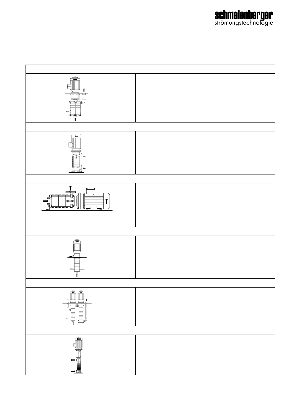
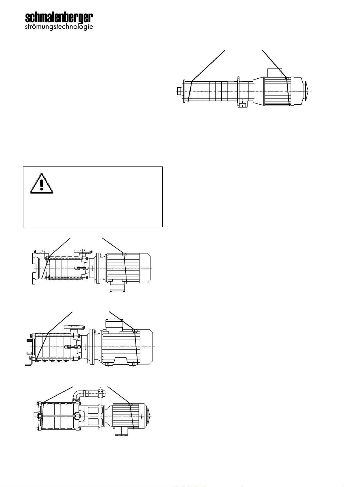
Pump Typ ZH- / TH- / DUO
Version: 27224 - E 5
1 General Details
1.1 User Information
This operator’s manual makes it easier to get to
know the centrifugal pump and to make full use
of its facilities.
The operator’s manual contains important in-
structions how to use the centrifugal pump safe-
ly, properly and economically. Your careful
attention to these instructions will help to avoid
danger, to reduce repair costs and breakdowns
and to increase the reliability and useful life of
the centrifugal pump.
The operator’s manual does not take account of
local regulations. The user is responsible for en-
suring that they are complied with.
The label specifies the machine series, the frame
size, the most important operating data and the
serial number. We request that you always quote
it in case of queries, when placing subsequent
orders and especially when ordering spare parts.
1.2 Usage Instructions
The centrifugal pump must only be used in ac-
cordance with the original pump specifications
and the operator´s manual. Any other usage or
operation where these figures are exceeded is
not permitted. The manufacturer is not liable for
damage resulting from such improper use.
The pump must only be operated in applications
that are described in the relevant documents.
• The pump must only be operated if it is in
flawless technical condition.
• The pump must not be operated if it is only
partially mounted.
• The pump may only be used to convey the
media described in the data sheet or in the
documentation for the relevant design.
• Never operate the pump without a pumping
medium.
• Pay careful attention to the information in the
data sheet or documentation regarding min-
imum delivery volume (to prevent damage
from overheating, damage to the bearings,
etc.).
• Pay careful attention to the information in the
data sheet or documentation regarding max-
imum delivery volume (to prevent overheat-
ing, damage to the mechanical seal,
cavitation damage, damage to the bearings,
etc.).
• Do not throttle the pump on the suction end
(to prevent cavitation damage).
• Coordinate other types of operation with the
manufacturer if they are not cited in the doc-
umentation or data sheet.
Preventing foreseeable misuse
• Never open the pressure-end shut-off ele-
ments beyond the permissible range
- Exceeding the maximum delivery volume
cited in the data sheet or documentation is
not permitted (possible cavitation damage)
• Never exceed the permissible operating lim-
its cited in the data sheet or documentation
in terms of pressure and temperature, etc.
• Comply with all safety instructions and direc-
tions in this operator's manual.
1.3 Relevant Documentation
Various documents are associated with every
centrifugal pump that comprise the technical
documentation of the pump. These are as fol-
lows:
• Operator’s manual
• Drive operator’s manual
• Manual for accessories listed in the specifi-
cations manual
• Acceptance report from the TÜV (Technical
Certification Authority) etc.
• Pilot run report
• Performance run report
• Installation drawing (dimensions sheet)
• Declaration of conformity with supplement
BA for ATEX pumps
• Declaration of conformity / Declaration of In-
corporation
• Specification with all data
Not all the above documentation has been pro-
duced and supplied in every case. For this
please check the details in the specification.
1.4 Technical Data / Specifications
The specifications of the centrifugal pump is the
most important document in every operator’s
manual. Contained therein are all the relevant
and technical data relating to the centrifugal
pump. It is the birth certificate of the centrifugal
pump and should be treated accordingly.