Schmidt SS 20.200 User manual

SCHMIDT®Flow Switch
SS 20.200
Instructions for Use

Instructions for Use SS 20.200 Page 2
SCHMIDT®Flow Switch
SS 20.200
Table of Contents
1 Important information.......................................................................3
2 Application range.............................................................................3
3 Mounting instructions.......................................................................4
4 Electrical connection........................................................................6
5 Commissioning................................................................................7
6 Switching threshold .........................................................................8
7 Service information..........................................................................9
8 Technical data...............................................................................10
9 Certificate of conformity.................................................................11
Imprint:
Copyright 2016 SCHMIDT Technology
All rights reserved.
Version: 505518.01C
Subject to modifications

Instructions for Use SS 20.200 Page 3
1 Important information
These instructions for use must be read completely and observed care-
fully, before putting the unit into operation.
Any claims under the manufacturer's liability for damage resulting from
non-observance or non-compliance with these instructions will become
void.
Tampering with the device in any way whatsoever - with the exception of
the designated use and the operations described in these instructions for
use - will forfeit any warranty and exclude any liability.
The unit is designed exclusively for the use described below (refer to
chapter 2). In particular, it is not designed for direct or indirect protection
of personal or machinery.
SCHMIDT Technology cannot give any warranty as to its suitability for a
certain purpose and cannot be held liable for errors contained in these
instructions for use or for accidental or sequential damage in connection
with the delivery, performance or use of this unit.
Symbols used in this manual
The symbols used in this manual are explained in the following section.
Danger warnings and safety instructions - read them care-
fully!
Non-observance of these instructions may lead to injury of the
personnel or malfunction of the device.
2 Application range
The SCHMIDT®Flow Switch SS 20.200 has been designed for station-
ary use in cleanrooms, air ducts or air shafts both under atmospheric
pressure conditions and overpressure up to 10 bar
1
. It measures the flow
velocity of the measuring medium as standard velocity (unit: m/s), rela-
tive to standard pressure of 1013.25 hPa and standard temperature of
20 °C. Thus the measurements resp. switching threshold is independent
of pressure and temperature of the medium.
An optional protective coating allows its use in dirty or aggressive media.
The resistance of the coating to the media occurring during operation
must be checked in each individual case.
When using the sensor outdoors, it must be protected against
direct exposure to the weather.
1
Only applicable with additional pressure protection measures
!
!

Instructions for Use SS 20.200 Page 4
3 Mounting instructions
The SS 20.200 is a high-precision and sensitive measuring device. Ac-
cordingly, the mechanical stress on the probe head must be minimised in
all mounting steps.
Avoid mechanical stress of the sensor tip as much as possible,
since otherwise irreversible damage can occur.
Mounting position
In order to achieve maximum measuring sensitivity, the sensor head
should be mounted pointing upwards. A sensor head pointing down-
wards must be avoided, since this will increase the measuring range limit
(nominal value 0.06 m/s).
In order to obtain good measurement results, the flow measuring sleeve
must always be in the centre of the flow duct.
The sensor head must immerse completely (that is, including
the temperature measuring sleeve) into the air flow. If this is not
the case, the measured value can be completely wrong.
The sensor should not be mounted in the proximity of heat sources,
since this may result in measurement errors. When used in ventilation
pipes equipped with heat exchangers, the sensor should always be
mounted upstream of the heat exchanger.
Wall mounting
First the protective cover must be pulled off the sensor head. Then the
sensor together with the threaded piece (M 18 x 1 fine pitch thread) is
screwed in the appropriate threaded bore of the duct wall. Set the de-
sired position and secure it with a counter nut.
Alternatively SCHMIDT Technology offers auxiliary installation equip-
ment. Please refer to following URLs for details:
www.schmidt-sensors.com or www.schmidttechnology.com
This also includes through-bolt joints that are suitable for use in media
with overpressure
2
in which the following has to be considered:
Mounting and dismounting of the sensor can be carried out only
as long as the system is in depressurized state.
Only using proper pressure-tight seals (e. g. Teflon tape).
Appropriate safety precautions are taken to avoid unintended
discarding of the sensor due to overpressure.
2
Pressure-tight, including pressure security kit (material no. 524891 and 524919)
!
!
!

Instructions for Use SS 20.200 Page 5
Pipe-bound flow
To reach the accuracy specified in the data sheets, the sensor has to be
positioned in a straight conduit and at a place with undisturbed flow pro-
file. An undisturbed flow profile can be achieved if a sufficiently long dis-
tance in front of the sensor (run-in distance L1) and behind the sensor
(run-out distance L2) is held absolutely straight and without disturbances
(such as edges, seams, bends, etc.).
The design of the run-out distance is also important, since disturbances
act not only in the direction of the air flow but can also lead to disturb-
ances opposite to the flow direction.
L1
L2
L
D
L
Total length of measuring distance
L2
Length of run-out distance
L1
Length of run-in distance
D
Diameter of the measuring distance
The following table shows the necessary straight conduit lengths as a
function of the pipe diameter D for various scenarios.
Flow obstacle upstream of measuring
conduit
Minimum length of
run-in distance
(L1)
Minimum length of
run-out distance
(L2)
Light bend (< 90°)
10 x D
5 x D
Contraction / reduction / 90° bend
15 x D
5 x D
2 bends 90° in one plane (2-dimensional)
20 x D
5 x D
2 bends 90° (3-dimensional change in two
directions)
35 x D
5 x D
Shut-off valve
45 x D
5 x D
This table lists the minimum values required in each case. If the listed
straight conduit lengths cannot be achieved, the measurement accuracy
may be impaired.
L

Instructions for Use SS 20.200 Page 6
4 Electrical connection
For proper operation the sensor requires a DC power supply with a nom-
inal value of 24 V with permitted tolerance of 20 %. Typical current con-
sumption is approx. 40 mA and at maximum 70 mA (without load of the
switching output), depending on the flow velocity.
Only operate sensor in the defined range of operating voltage
(24 VDC ± 20 %).
Undervoltage may result in malfunction; overvoltage may lead
to irreversible damages.
The specifications for the operating voltage are valid for the internal con-
nection of the sensor. Voltage drops generated due to cable resistances
must be considered by the customer.
Connecting cable assignment
The sensor is equipped with a cable firmly fixed to its housing with 2 m
length and open cable ends (pin assignments see following graphic).
Sensor
+24V
R1 RON
R2
Gnd
WH (white)
YE (yellow)
GN (green) Z
During electrical installation ensure that no voltage is applied
and inadvertent activation is not possible.
For signalling, a semiconductor relay is used. Its galvanically decoupled
switching output has a maximum permanent switching power of 300 mW
(Ron with typically 20 , up to max. 25 ). The switching current should
be at most 100 mA, the peak value of the switching voltage (AC or DC)
must not exceed 30 V. Otherwise the bidirectional protecting diode (Z)
between the load circuit terminals will break down and can be thermally
destroyed (see connecting diagram).
The specified electrical operating values must not be exceeded.
Exceeding them may lead to irreversible damage.
!
!
!

Instructions for Use SS 20.200 Page 7
5 Commissioning
Status signalling
The SS 20.200 has two light emitting diodes (LED) of different colours,
indicating its current status (depending on the switching behaviour or-
dered).
The following table shows the signalling options and their cause.
Sensor status
LED
green
LED
red
Relay
output
Supply voltage:
- not connected / cable broken
- poles reversed
- too low (< 19.2 V)
Open
Initialisation (after switching on)
Open
Sensor defective
Open
Sensor ready
Switching threshold1 underrun / exceeded
Closed /
Open
Sensor ready
Switching threshold3exceeded / underrun
Open /
Closed
Legend: = LED off = LED flashing (2 Hz) = LED on
Startup
Before switching on it must be checked if the SS 20.200 is installed cor-
rectly, both mechanically and electrically.
The sensor is ready within 20 s, after applying the operating voltage.
During this initialisation stage, the green LED is flashing.
As soon as the green LED is lit permanently, the sensor is ready.
If the sensor detects an internal defect, the green LED will go off and the
red LED is flashing.
In case of defects the sensor must be sent in to SCHMIDT for repair.
3
Depending on the sensor configuration ordered.

Instructions for Use SS 20.200 Page 8
6 Switching threshold
The switching output will trip at an adjustable flow velocity. There are two
basic types of setting the switching threshold:
Manual setting (order code L = P)
The switching threshold is set using the potentiometer mounted on the
front side of the SS 20.200. To increase the switching threshold, rotate
the potentiometer clockwise and visa-versa. The measuring range of the
sensor is correlated linearly with the 270 degrees of rotating, i.e., at the
upper end (clockwise) the switching threshold is 95 % of the measuring
range. At the lower end (zero point) the switching threshold is limited to
5 % of the measuring range.
The potentiometer has a slot size of 2.5 mm x 0.5 mm.
The maximum applicable torque at the potentiometer dead
stops is 3.5 Ncm.
With order code xx = 00, the potentiometer is set at about 50% (default).
At a distinct value xx > 00, the potentiometer is set ex works to the de-
sired switching threshold („xx“ % of measuring range).
The individual setting of the switching point is done by adjusting the flow
velocity to the desired threshold value. Then the potentiometer is rotated
from the zero point clockwise until the relay is switching. The release
point is then offset downward by the hysteresis (see also chapter: Hyste-
resis of switching threshold). For fine adjustment, the potentiometer can
now be rotated back a little bit.
Preprogramed switching threshold (order code L = F)
If the flow velocity to be monitored is already known at the time of order-
ing, the sensor can be ordered with a fixed, preprogramed switching
threshold. In this case, the potentiometer is put out of action and a stick-
er on the front side of the sensor informs about the programmed switch-
ing threshold.
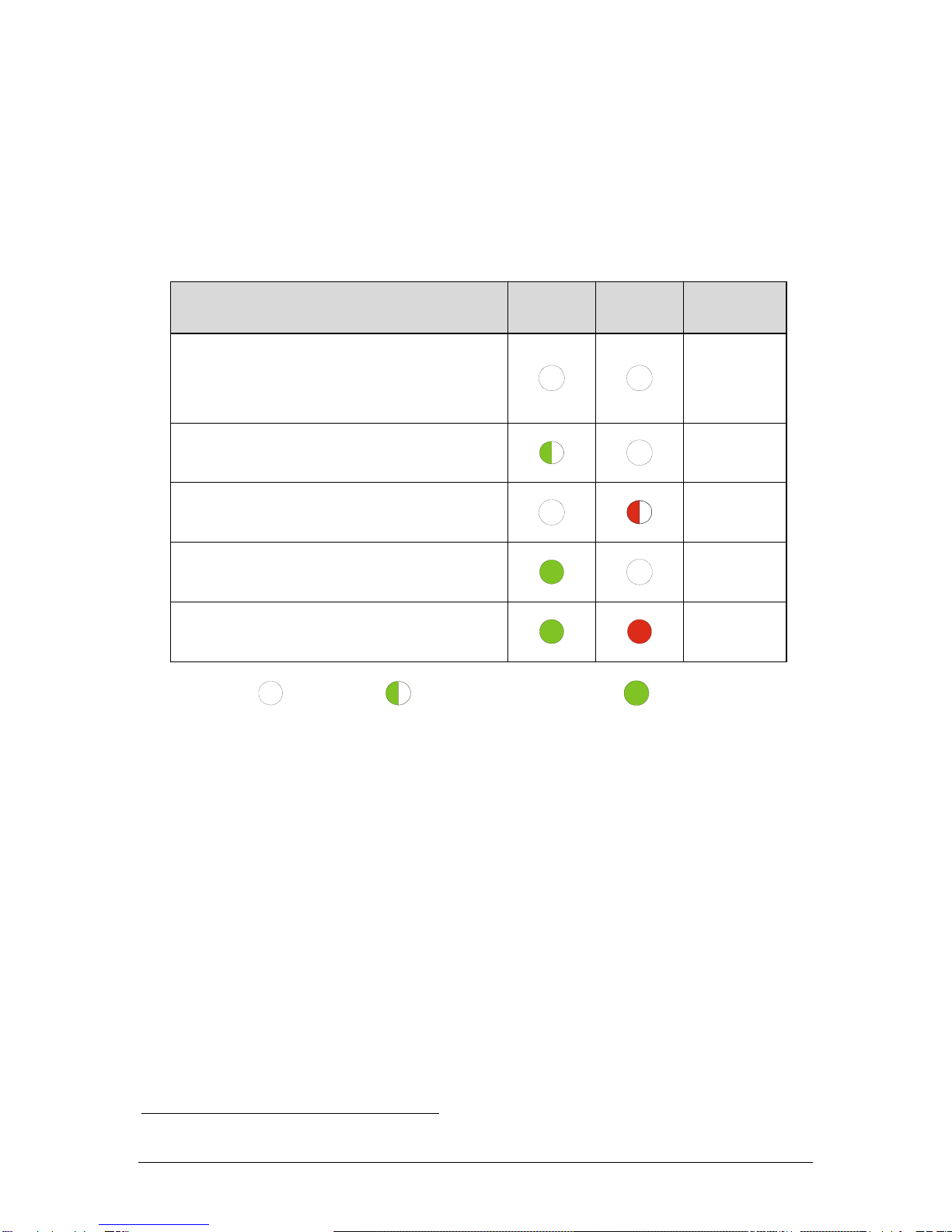
Hysteresis of switching threshold
The hysteresis of the switching threshold is defined as the value that
separates the switching point (SP) from the release point (RP). It is im-
portant which switching logic (S) was selected.
For S = 1 and S = 2, the sensor switches directly at the defined SP. RP
is lower by 5 % of the measuring range.
For S = 3 and S = 4, SP is 5 % above the preset value. In this case, RP
coincides exactly with the preset value.
!

Instructions for Use SS 20.200 Page 9
7 Service information
Maintenance
Heavy contamination of the sensor head may lead to false measured
values. Therefore, the sensor head must be checked for contamination
at regular intervals. If contaminations are visible, the sensor can be
cleaned as described below.
Cleaning the sensor tip
The sensor head can be cleaned to remove dust or dirt by moving it
carefully in warm water containing a dishwashing liquid or other allowed
cleaning liquid (e.g. isopropanol)
4
. Persistent incrustations or deposits
can be previously softened by prolonged immersion and then removed
by means of a soft brush or cloth. Avoid applying force to the sensitive
sensor tip.
The sensor head is a sensitive measuring system.
During manual cleaning proceed with great care.
Before putting it again into operation, wait until the sensor head is com-
pletely dry.
Sterilization
Both uncoated and coated sensors can be sterilized during operation.
Alcohols (drying without leaving residues) and hydrogen peroxide (un-
coated version only) are approved and certified disinfectants.
Spare parts or repair
No spare parts are available, since a repair is only possible at SCHMIDT
Technology. In case of defects, the sensors must be sent in to the sup-
plier for repair.
When the sensor is used in systems important for operation, we recom-
mend keeping a replacement sensor in stock.
Test certificates and material certificates
Every newly produced sensor is accompanied by a certificate of compli-
ance according to EN 10204-2.1. Material certificates are not available.
4
Other cleaning agents upon request.
!

Instructions for Use SS 20.200 Page 10
8 Technical data
Measuring quantity
Standard velocity wNof air, based on standard condi-
tions of 20 °C and 1013.25 hPa
Measuring medium
Air or nitrogen
Measuring range wN
0 ... 1 / 2.5 / 10 / 20 m/s
Lower detection limit wN
0.06 m/s
Switching threshold wN
5 ... 95 % of measuring range; min. 0.1 m/s
Switching threshold setting
Standard: Potentiometer (single turn: 270°)
Option: Pre-programmed
Switching hysteresis
5 % of switching threshold, min. 0.05 m/s
Reproducibility wN
±(2 % of switching threshold + 0.1 m/s)
Response time (t90 ) wN
3 s (jump from 0 to 5 m/s)
Temperature gradient wN
< 2 K/min (at 5 m/s)
Switch-on delay during start-up
20 s
Operating temperature
Sensor probe: -20 ... +85 °C
Electronics: -20 ... +70 °C
Storage temperature
-20 ... +85 °C
Humidity range
0 ... 95 % of rel. humidity (RH); none-condensing
Operating pressure
0 …10 bar (overpressure)
Operating voltage UB
24 VDC ± 20 %
Current consumption
typ. < 40 mA (max. 70 mA)5
Switching relay
30 VPeak / 100 mA / 300 mW
Display LED
Green: sensor status
Red: switching status / sensor defective
Electrical connection
Non-detachable cable, pigtail6, 4 x 0.14 mm2, length
2 m, PVC (grey), Outer-Ø 3.8 mm
Maximum cable length
100 m
Protection type of housing
IP65 (with plug); IP52 (potentiometer open)
Protection type of probe tip
IP67
Protection class
III (SELV) or PELV (EN 50178)
Minimum immersion depth
58 mm
Sensor tube diameter
9 mm
Mounting length
100 / 200 / 350 / 500 mm
Materials
Housing: PBT (Ultradur B4300 G4)
Probe: stainless steel 1.4571, PBT
Coating: Polyurethanderivat
5
Without signal current of switching output
6
With cable end sleeves

Instructions for Use SS 20.200 Page 11
9 Certificate of conformity

Instructions for Use SS 20.200 Page 12
SCHMIDT Technology GmbH
Feldbergstraße 1
78112 St. Georgen
Germany
Phone +49 (0)7724 / 899-0
Fax +49 (0)7724 / 899-101
Email sensors@schmidttechnology.de
URL www.schmidt-sensors.com
Table of contents
Popular Switch manuals by other brands

Extron electronics
Extron electronics MMX 42 AV RCA Specification sheet

Fujitsu
Fujitsu Servis Multi FS-1004MT user manual

Hawking
Hawking GS400T Specifications

Endress+Hauser
Endress+Hauser Liquiphant FTL64 operating instructions

ZyXEL Communications
ZyXEL Communications ExtraSmart ES-1552 user guide

Raven
Raven Slingshot Field Hub troubleshooting guide