SCHMITT Acuity AR100 User manual

© 2018 Schmitt Industries
Acuity AR100
Triangulation Sensor Manual
Revision 1.1 on 2.6.2018
© 2018 Schmitt Industries
2765 NW Nicolai St.
Portland, OR 97210 USA
sales@acuitylaser.com
Tel: +1 503.227.7908
Fax: +1 503.223.1258
Acuitylaser.com
Acuity is a product line of
schmittindustries.com

AR100 Operation Manual
© 2018 Schmitt Industries Revision 1.1
2
Table of Contents
Safety Precautions..............................................................................................4
CE compliance....................................................................................................4
Laser safety.........................................................................................................4
General information............................................................................................4
Basic technical data ...........................................................................................5
Options to designate when ordering the AR100..............................................6
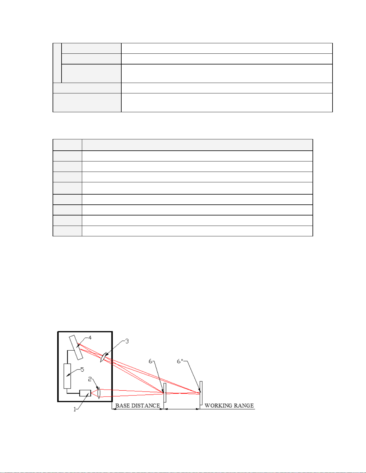
Structure and operational principle ..................................................................6
Dimensions and mounting.................................................................................7
Overall and mounting dimensions...........................................................................7
Overall demands for mounting.................................................................................7
Connection..........................................................................................................8
Configuration parameters..................................................................................8
Time limit for integration ..........................................................................................8
Sampling mode..........................................................................................................9
Sampling period ........................................................................................................9
Zero point.................................................................................................................10
Line AL operation mode .........................................................................................10
Time lock of the result ............................................................................................12
Method of results averaging...................................................................................12
Number of averaged values/time of averaging......................................................12
Factory parameters table........................................................................................12
Description of RS232 and RS485 interfaces...................................................13
RS232 port...............................................................................................................13
RS485 port...............................................................................................................13
Serial data transmission format.............................................................................13
Modes of data transfer............................................................................................13
Communication sessions types.............................................................................13
Configuration parameters.......................................................................................14
Rate of data transfer through serial port ................................................................14
Net address...........................................................................................................14
Factory parameters table.......................................................................................14
Acuity protocol (binary format)..............................................................................14
Request.................................................................................................................14
Answer ..................................................................................................................15
Data stream...........................................................................................................16
Output rate............................................................................................................16
Request code table................................................................................................16
Notes.....................................................................................................................18
Modbus RTU protocol (binary format)...................................................................22
Input Registers (Read only)...................................................................................22
Holding Registers (Read / Write)...........................................................................22
ASCII format ............................................................................................................23

AR100 Operation Manual
© 2018 Schmitt Industries Revision 1.1
3
Analog outputs..................................................................................................25
Current output 4…20 mA........................................................................................25
Voltage output 0…10 V ...........................................................................................26
Configuration parameters................................................................................26
Range of the analog output ...................................................................................26
Analog output operation mode...............................................................................27
Factory parameters table........................................................................................27
Parameterization program ...............................................................................27
Function...................................................................................................................27
Program setup.........................................................................................................27
Obtaining connection to sensor (RS232/RS485)...................................................28
Checking of the sensor operability........................................................................29
Connection via the ASCII interface........................................................................30
Connection via the Modbus RTU protocol ............................................................31
Display, gathering and scanning of data...............................................................32
Setting and saving parameters of the sensor .......................................................33
Setting parameters................................................................................................33
Automatic data stream mode after power switch on...............................................34
Saving parameters ................................................................................................34
Saving and writing a set of parameters..................................................................34
Recovery of default parameters.............................................................................35

AR100 Operation Manual
© 2018 Schmitt Industries Revision 1.1
4
Safety Precautions
•Use supply voltage and interfaces indicated in the sensor specifications
•In connection/disconnection of cables, the sensor power must be switched
off
•Do not use sensors in locations close to powerful light sources
•To obtain stable results, wait about 20 minutes after sensor activation to
achieve uniform sensor warm-up
CE compliance
The sensors have been developed for use in industry and meet the requirements
of the following Directives:
•EU directive 2014/30/EU. Electromagnetic compatibility (EMC).
•EU directive 2011/65/EU, “RoHS“category 9.
Laser safety
The sensors make use of a c.w. 660 nm (or 405 nm, 450 nm) wavelength
semiconductor laser. The maximum output power is 0.95 mW. The sensors
belong to the 2 laser safety class. The following warning label is placed on the
sensor body:
The following safety measures should be taken while operating the sensor:
•Do not target the laser beam to humans;
•Do not disassemble the sensor;
•Avoid staring into the laser beam.
General information
The sensors are intended for non-contact measuring and checking of position,
displacement, dimensions, surface profile, deformation, vibrations, sorting and
sensing of technological objects as well as for measuring levels of liquid and bulk
materials.

AR100 Operation Manual
© 2018 Schmitt Industries Revision 1.1
5
The series includes 6 models of sensors with the measurement range from 10 to
500 mm and the offset distance from 20 to 105 mm.
There are two options of laser sensors: RED laser (660 nm) or BLUE laser (405
or 450 nm). The use of blue lasers instead of conventional red lasers greatly
enhances capabilities of the sensors, in particular, for such uses as control of
high-temperature objects and organic materials.
Basic technical data
AR100
-10
-25
-50
-100
-250
-500
Base distance, mm
20
20
30
50
65
105
Range, mm
10
25
50
100
250
500
Linearity, %
±0.05% of the range
±0.1%
Resolution, %
0.01% of the range (for the digital output only)
0.02%
Temperature drift
0.02% of the range per /°С
Max. measurement
frequency, Hz
9,400 Hz
Light source
red semiconductor laser, 660 nm wavelength;
blue or UV semiconductor laser, 405 nm or 450 nm wavelength
(BLUE version)
Output power
≤0.95 mW
Laser safety class
2 (IEC60825-1)
Output interface:
digital
RS232 or RS485 (max. 921.6 Kbit/s)
analog
4…20 mA (load
500 Ohm) or 0…10
Synchronization
input
2.4 – 24 Volts
Logic output
programmed functions, NPN: 100 mA max; 40 V max
Power supply
9 …36 Volts
Power consumption
1.5..2 Watts
Environmental
resistance:
Enclosure rating
IP67
Vibration
20 g /10…1000 Hz, 6 hours for each of XYZ axes
Shock
30 g / 6 ms
Operating
ambient
temperature
-10…+60 °С
Permissible
10,000

AR100 Operation Manual
© 2018 Schmitt Industries Revision 1.1
6
ambient light, lux
Relative humidity
5-95% (no condensation)
Storage
temperature
-20…+70 °С
Housing material
aluminum
Weight (without
cable)
40 gram
Options to designate when ordering the AR100
Description
1
Red or Blue laser option (450 nm)
2
Measurement range, mm
3
The type of serial interface: 232 (RS232) or 485 (RS485)
4
Analog output of either: 4…20 mA (I) or 0…10 Volts (U)
5
Synchronization input
6
User programmable input/output signal
7
Standard cable length is 2 meter with options for longer cable lengths
Structure and operational principle
Operation of the sensors is based on the principle of optical triangulation
(Figure 1). Radiation of a semiconductor laser (1) is focused by a lens (2) onto an
object (6). Radiation reflected by the object is collected by a lens (3) onto a linear
CMOS array (4). Moving the object (6 - 6') causes the corresponding shift of the
image. A signal processor (5) calculates the distance to the object from the
position of the light spot on the array (4).
Figure 1

AR100 Operation Manual
© 2018 Schmitt Industries Revision 1.1
7
Dimensions and mounting
Overall and mounting dimensions
Overall and mounting dimensions of the sensors are shown in Figure 2. The
sensor housing is made of anodized aluminum. The front panel of the housing
has a glass window. The housing also contains mounting holes. The cable is
mounted on the sensor without connector.
Overall demands for mounting
The sensor is positioned so that the object under control has to be placed in the
working range of the sensor. In addition, no foreign objects should be allowed to
stay on the path of the incident and reflected laser radiation.
Where the objects to be controlled have intricate shapes and textures, the
incidence of mirror component of the reflected radiation to the receiving window
should be minimized.

AR100 Operation Manual
© 2018 Schmitt Industries Revision 1.1
8
Connection
Assignment of the cable wires is shown in the table below:
Model of the
sensor
Pin number
Assignment
Wire color
232-U/I-IN-AL
free lead
free lead
DB9
DB9
free lead
free lead
free lead
DB9
-
-
2
3
-
-
-
5
Power 9 to 36 Volts+
Ground (power)
TXD
RXD
Voltage / Current
IN
AL
Ground (common for
signals)
Red
Brown
Green
Yellow
Blue
Violet
Orange
Black
485-U/I-IN-AL
free leads
Power 9 to 36 Volts+
Ground (power)
DATA+
DATA-
Voltage / Current
IN
AL
Ground (common for
signals)
Red
Brown
Green
Yellow
Blue
Violet
Orange
Black
Configuration parameters
The nature of operation of the sensor depends on its configuration parameters,
which can be changed only by transmission of commands through serial port
RS232 or RS485. The basic parameters are as follows:
Time limit for integration
Intensity of the reflected radiation depends on the surface characteristics of the
object under control. Therefore, the output power of the laser and the time of
integration of radiation incident onto the CMOS-array are automatically adjusted
to achieve the maximum measurement accuracy.

AR100 Operation Manual
© 2018 Schmitt Industries Revision 1.1
9
Parameter "time limit for integration" specifies the maximum allowable time of
integration. If the radiation intensity received by the sensor is so small that no
reasonable result is obtained within the time of integration equal to the limiting
value, the sensor transmits a zero value.
Note 1. The measurement frequency depends on the integration time of the
receiving array. The maximum frequency (9.4 kHz) is achieved for the integration
time ≤106 μs (minimum possible integration time is 3 μs). As the integration time
increases above 106 μs, the result updating time reduces proportionally.
Note 2. Increasing of this parameter expands the possibility of control of low-
reflecting (diffuse component) surfaces; at the same time this leads to reduction
of measurement frequency and increases the effects of exterior light
(background) on the measurement accuracy. Factory setting of the limiting time
of integration is 3200 μs.
Note 3. Decreasing of this parameter lets to increase the measurement
frequency, but can decrease the measurement accuracy.
Sampling mode
This parameter specifies one of the two result sampling options in the case
where the sensor works in the data stream mode:
•Time Sampling;
•Trigger Sampling.
When Time Sampling is selected, the sensor automatically transmits the
measurement result via serial interface in accordance with the selected time
interval (sampling period).
When Trigger Sampling is selected, the sensor transmits the measurement result
when the external synchronization input (IN input of the sensor) is switched and
taking the division factor set into account.
Sampling period
If the Time Sampling mode is selected, the ‘sampling period’ parameter
determines the time interval in which the sensor will automatically transmit the
measurement result. The time interval value is set in increments of 1 μs.
If the Trigger Sampling mode is selected, the ‘sampling period’ parameter
determines the division factor for the external synchronization input. For
example, for the parameter value equal to 100, data are transmitted through bit-
serial interface when each 100th synchronizing pulse arrives at IN input of the
sensor.
Note 1. It should be noted that the ‘sampling mode’ and ‘sampling period’
parameters control only the transmission of data. The sensor operation algorithm

AR100 Operation Manual
© 2018 Schmitt Industries Revision 1.1
10
is built so that measurements are taken at a maximum possible rate determined
by the integration time period, the measurement results are sent to buffer and
stored therein until a new result arrives. The above-mentioned parameters
determine the method of the readout of the result form the buffer.
Note 2. If the bit-serial interface is used to receive the result, the time required for
data transmission at selected data transmission rate should be taken into
account in the case where small sampling period intervals are used. If the
transmission time exceeds the sampling period, it is this time that will determine
the data transmission rate. The calculation of time required to transmit the result
is given on p.16.
Note 3. It should be taken into account that the sensors differ in some variation in
the parameters of the internal generator, which affects the accuracy of the Time
Sampling period.
Zero point
This parameter sets a zero point of absolute system of coordinates in any point
within the limits of a working range. You can set this point by corresponding
command or by connecting AL input to the ground line (this input must
beforehand be set to mode 4). When the sensor is fabricated, the base distance
is set with a certain uncertainty, and, if necessary, it is possible to define the
point zero more accurately.
Line AL operation mode
This line can work in one of the eight modes defined by the configuration
parameter value:
•mode 1: indication of run-out beyond the range;
•mode 2: mutual synchronization of two or more sensors (slave);
•mode 3: mutual synchronization of two or more sensors (master);
•mode 4: hardware zero-set line;
•mode 5: hardware laser switch OFF/ONN;
•mode 6: encoder;
•mode 7: input;
•mode 8: reset of the Ethernet packets counter.
In the "Indication of run-out beyond the range" mode, logical “1” occurs on the AL
line if an object under control is located within the working range of the sensor
(within the selected window in the range), and logical "0" occurs if the object is
absent in the working range (within the selected window). For example, in such
mode this line can be used for controlling an actuator (a relay), which is activated
when the object is present (absent) within the selected range (Fig. 6.1).

AR100 Operation Manual
© 2018 Schmitt Industries Revision 1.1
11
The "Mutual synchronization" mode makes it possible to synchronize
measurement times of two and more sensors. It is convenient to use this mode to
control one object with several sensors, e.g., in the measurement of thickness.
On the hardware level, synchronization of the sensor is effected by combining AL
lines (Fig. 6.2.). Using the parameterization program, one of the sensors should
be set to the "Master" mode, and the rest - to the "Slave" mode.
In the "Hardware zero-set" mode, connection AL input to the ground potential
sets the beginning of coordinates into the current point (Fig. 6.3.)*.
In the "Hardware laser switch OFF/ON" mode, connection AL input to the ground
potential switches the laser ON/OFF (Fig. 6.3.)*.
In the "Encoder" mode, the AL and IN lines work as inputs of quadrature signals.
In this mode, the encoder can be connected to these lines, and the
measurements will be synchronized with the encoder.
In the "Input" mode, the AL line state is transmitted in the status word in the
Ethernet packet.
In the "Reset of the Ethernet packets counter" mode, connection AL input to the
ground potential resets the counter (Fig. 6.3.)*.
*Note. A low level of the AL line is holding for 100 μs or more, and a high level of
the AL line is holding for 100 μs.
Out of the range
indication
Mutual synchronization
Hardware zero-set/
Hardware laser ON/OFF
Figure 6.1.
Figure 6.2.
Figure 6.3.

AR100 Operation Manual
© 2018 Schmitt Industries Revision 1.1
12
Time lock of the result
If the sensor does not find the object or if the authentic result cannot be received,
a zero value is transferred. The given parameter sets time during which the last
authentic result is transferred.
Method of results averaging
This parameter defines one of the two methods of averaging of measurement
results implemented directly in the sensor:
•Averaging over a number of results
•Time averaging
When averaging over a number of results is selected, sliding average is
calculated.
When time averaging is selected, the results obtained are averaged over the time
interval chosen.
Number of averaged values/time of averaging
This parameter specifies the number of source results to be averaged for
deriving the output value or time of the averaging.
The use of averaging makes it possible to reduce the output noise and increase
the sensor resolution.
Averaging over a number of results does not affect the data update in the sensor
output buffer.
In case of time averaging, data in the output buffer are updated at a rate equal to
the averaging period.
Note. The maximum value is 127.
Factory parameters table
The sensors are supplied with the parameters shown in the table below:
Parameter
Value
Time limit for integration
3200 (3.2 milliseconds)
Sampling mode
time
Sampling period - microseconds
5000 (5 milliseconds)
Point of zero
Beginning of the range
Line AL operation mode
1
Time lock of the result
2 (10 milliseconds)
Method of results averaging
Over a number of results
Number of averaged values
1

AR100 Operation Manual
© 2018 Schmitt Industries Revision 1.1
13
The parameters are stored in nonvolatile memory of the sensor. Correct
changing of the parameters is carried out by using the parameterization program
supplied with the sensor or a user program.
Description of RS232 and RS485 interfaces
Data exchange with the sensor is carried out over the Acuity or Modbus RTU
protocols in binary format or in the ASCII format. The protocol and the data
format are selected using the parameterization program.
RS232 port
The RS232 port ensures a “point-to-point” connection and allows the sensor to
be connected directly to RS232 port of a computer or controller.
RS485 port
In accordance with the protocol accepted and hardware capability, the RS485
port makes it possible to connect up to 127 sensors to one data collection unit by
a common bus circuit.
Serial data transmission format
Data message has the following format:
1 start-bit
8 data bits
1 even bit
1 stop-bit
Modes of data transfer
Through these serial interfaces the measurement data can be obtained by two
methods:
•by single requests (inquiries);
•by automatic data streaming (stream).
Communication sessions types
The communications protocol is formed by communication sessions, which are
only initiated by the ‘master’ (PC, controller). There are two kinds of sessions
with such structures:
1) “request”, [“message”] — [“answer”], square brackets include optional
elements.
2) “request” — “data stream” — [“request”].

AR100 Operation Manual
© 2018 Schmitt Industries Revision 1.1
14
Configuration parameters
Rate of data transfer through serial port
This parameter defines the rate of data transmission via the bit-serial interface in
increments of 2,400 bit/s. For example, the parameter value equal to 4 gives the
transmission rate of 2400*4 = 9600 bit/s.
Note. The maximum transmission rate for RS232 and RS485 interfaces is 921.6
Kbit/s.
Net address
This parameter defines the network address of the sensor equipped with RS485
interface.
Note. The network data communication protocol assumes the presence of a
‘master’ in the net, which can be a computer or other information-gathering
device, and from 1 to 127 ‘slaves’ (AR100 Series sensors) which support the
protocol.
Each ‘slave’ is assigned a unique network identification code – a device address.
The address is used to form requests or inquiries all over the net. Each slave
receives inquiries containing its unique address as well as ‘0’ address which is
broadcast-oriented and can be used for formation of generic commands, for
example, for simultaneous latching of values of all sensors and for working with
only one sensor (with both RS232 port and RS485 port).
Factory parameters table
Parameter
Value
Baud rate (RS232 or RS485)
9600 bit/s
Net address
1
Mode of data transfer
request
Acuity protocol (binary format)
Request
'Request' is a two-byte message, which fully controls a communication session
and can be transmitted by the 'master'. The ‘request’ message is the only one of
all messages in a session where the most significant bit is set at 0, therefore, it
serves to synchronize the beginning of the session. In addition, it contains the
device address (ADR), code of request (COD) and, optionally, the message
[MSG].
Request format ('master'):

AR100 Operation Manual
© 2018 Schmitt Industries Revision 1.1
15
Byte
Bits
Description
7
6
5
4
3
2
1
0
0
0
ADR
network address
1
1
0
0
0
COD
code of request
2
1
0
0
0
MSG[0] lo
lower tetrad of the 0th byte
3
1
0
0
0
MSG[0] hi
higher tetrad of the 0th byte
4
1
0
0
0
MSG[1] lo
lower tetrad of the 1st byte
5
1
0
0
0
MSG[1] hi
higher tetrad of the 1st byte
...
...
...
...
...
...
Answer
'Answer' is the data burst that can be transmitted by ‘slave’ in the course of the
session.
All messages with a message burst contain 1 in the most significant digit. Data in
a message are transferred in tetrads. When byte is transmitted, lower tetrad goes
first, and then follows higher tetrad. When multi-byte values are transferred, the
transmission begins with lower byte.
When ‘answer’ is transmitted, the message contains:
•SB-bit, characterizes the updating of the result. If SB is equal to "1", this
means that the sensor has updated the measurement result in the
buffer, if SB is equal to "0" - then non-updated result has been
transmitted. SB=0 when parameters transmit;
•two additional bits of cyclic binary batch counter (CNT). Bit values in the
batch counter are identical for all sending’s of one batch. The value of
batch counter is incremented by the sending of each burst and is used
for formation (assembly) of batches or bursts as well as for control of
batch losses in receiving data streams.
The following is the format of the ‘answer’ data burst for the message
transmission (MSG):
Byte
Bits
Description
7
6
5
4
3
2
1
0
0
1
SB
CNT
MSG[0] lo
lower tetrad of the 0th byte
1
1
SB
CNT
MSG[0] hi
higher tetrad of the 0th byte
2
1
SB
CNT
MSG[1] lo
lower tetrad of the 1st byte
3
1
SB
CNT
MSG[1] hi
higher tetrad of the 1st byte
...
...
...
...
...
...

AR100 Operation Manual
© 2018 Schmitt Industries Revision 1.1
16
Data stream
‘Data stream’ is an infinite sequence of data bursts or batches transmitted from
‘slave’ to ‘master’, which can be interrupted by a new request. In transmission of
‘data stream’ one of the ‘slaves’ fully holds a data transfer channel, therefore,
when ‘master’ produces any new request sent to any address, data streaming
process is stopped. Also, there is a special request to stop data streaming.
Output rate
Output rate ("OR") depends on Baud rate of serial interface ("BR"), and is
calculated by such a manner:
OR = 1 / (44/BR+1*10-5) Hz
For example, for BR=460800 b/s, Output rate = 9.4 kHz.
Request code table
Reque
st
code
Description
Message
(size in bytes)
Answer
(size in bytes)
01h
Device identification
—
- device type
(1)
-
firmware version
(1)
- serial number
(2)
- base distance
(2)
- range (2)
02h
Read a parameter
- code of parameter
(1)
- value of parameter
(1)
03h
Write a parameter
- code of parameter
(1)
- value of parameter
(1)
—
04h
Store current parameters to
FLASH-memory
- constant AAh
(1)
- constant AAh
(1)
04h
Recover default values of
parameters in FLASH-memory
- constant 69h
(1)
- constant 69h
(1)
05h
Latch a current result
—
—
06h
Request a result
—
- result (2)
07h
Request a stream of results
—
- stream of result
(2)
08h
Stop data streaming
—
—

AR100 Operation Manual
© 2018 Schmitt Industries Revision 1.1
17
1.1.1. List of parameters
Code of
paramet
er
Description
Values
00h
Sensor ON
1 — laser is ON, measurements are taken
(default);
0 — laser is OFF, sensor in power save
mode.
01h
Analog output ON
1 — analog output is ON;
0 — analog output is OFF.
02h
Control of averaging,
sampling, AL and analog
output
x,M2,A,С,M1,M0,R,S – control byte which
determines the operation mode.
M2:M1:M0 bits (AL mode):
000 - out of the range indication (by
default);
001 - 'slave' mode (mutual
synchronization);
010 - hardware zero set mode;
011 - laser switch OFF/ON;
100 - encoder mode;
101 - input mode;
110 - reset of the Ethernet packets
counter;
111 - 'master' mode (mutual
synchronization).
Abit (averaging mode):
0 - averaging over a number of
results (by default);
1 - time averaging (5 ms).
C bit is not used
Rbit (analog output mode):
0 - window mode (by default);
1 - full range.
S bit (sampling mode):
0 - time sampling (by default);
1 - trigger sampling.
x bit is not used
03h
Network address
1…127 (default — 1)
04h
Rate of data transfer
through a serial port
1…192 (default — 4), specifies data
transfer rate in increments of 2400 baud;
e.g., 4 means the rate of 4*2400=9600
baud.
05h
Reserved
06h
Number of averaged values
1…128 (default — 1)

AR100 Operation Manual
© 2018 Schmitt Industries Revision 1.1
18
07h
Reserved
08h
Lower byte of the sampling
period
1) 10…65535 (default — 5000)
The time interval in increments of 1 μs with
which sensor automatically communicates
the results on streaming request (priority of
sampling = 0).
2) 1…65535 (default — 5000)
Divider ratio of trigger input (priority of
sampling = 1).
09h
Higher byte of the sampling
period
0Ah
Lower byte of maximum
integration time
2…3200 (default – 3200)
The limiting time of integration by CMOS-
array in increments of 1 μs.
0Bh
Higher byte of maximum
integration time
0Ch
Lower byte for the
beginning of analog output
range
0…16383 (default – 0)
0Dh
Higher byte for the
beginning of analog output
range
0Eh
Lower byte for the end of
analog output range
0…16383 (default – 16383)
0Fh
Higher byte for the end of
analog output range
10h
Time lock of result
0…255, specifies the time interval in
increments of 5 milliseconds.
11…16h
Reserved
17h
Lower byte of a zero point
0…16383 (default — 0), specifies the
beginning of absolute coordinate system.
18h
Higher byte of a zero point
19…88h
Reserved
89h
Autostart of the stream
when the sensor is turned
on (after 20 seconds)
1 — Autostart is ON;
0 — Autostart is OFF (default).
8Ah
Protocols for RS232/RS485
interfaces
0 — ACUITY protocol (default);
1 — ASCII protocol;
2 — MODBUS RTU protocol.
Notes
•All values are given in binary form.
•Base distance and range are given in millimeters.
•The value of the result transmitted by a sensor (D) is so normalized that
4000h (16384) corresponds to a full range of the sensor (S in mm),
therefore, the result in millimeters is obtained by the following formula:

AR100 Operation Manual
© 2018 Schmitt Industries Revision 1.1
19
X=D*S/4000h (mm) (1)
•On special request (05h), the current result can be latched in the output
buffer where it will be stored unchanged up to the moment of arrival of
request for data transfer. This request can be sent simultaneously to all
sensors in the net in the broadcast mode in order to synchronize data
pickup from all sensors.
•When working with the parameters, it should be borne in mind that
when power is OFF the parameter values are stored in nonvolatile
FLASH-memory of the sensor. When power is ON, the parameter
values are read out to RAM of the sensor. In order to retain these
changes for the next power-up state, a special command for saving
current parameter values in the FLASH-memory (04h) must be run.
•Parameters with the size of more than one byte should be saved
starting from the high-order byte and finishing with the low-order byte.
•ATTENTION! It is not recommended to configure the network
addresses of the sensors connected to the network using the "common
bus" scheme (RS485).
1.1.2. Examples of communication sessions
1) Request: "Device identification".
Conditions: device address - 1, request code - 01h, device type - 63 (3Fh),
firmware version - 144 (90h), serial number - 17185 (4321h), base distance - 80
mm (0050h), measurement range - 50 mm (0032h), packet number (CNT) - 1,
result update flag (SB) - 0.
Request ('master'):
Byte
Bits
Value
Description
7
6
5
4
3
2
1
0
0
0
0
0
0
0
0
0
1
01h
Network address
1
1
0
0
0
0
0
0
1
81h
Request code
Answer ('slave'):
Byte
Bits
Value
Description
7
6
5
4
3
2
1
0
0
1
0
0
1
1
1
1
1
9Fh
Lower tetrad of the device type
1
1
0
0
1
0
0
1
1
93h
Higher tetrad of the device type
2
1
0
0
1
0
0
0
0
90h
Lower tetrad of the firmware version
3
1
0
0
1
1
0
0
1
99h
Higher tetrad of the firmware version
4
1
0
0
1
0
0
0
1
91h
Lower tetrad of the 0th byte of a serial
number
5
1
0
0
1
0
0
1
0
92h
Higher tetrad of the 0th byte of a serial
number
6
1
0
0
1
0
0
1
1
93h
Lower tetrad of the 1st byte of a serial

AR100 Operation Manual
© 2018 Schmitt Industries Revision 1.1
20
number
7
1
0
0
1
0
1
0
0
94h
Higher tetrad of the 1st byte of a serial
number
8
1
0
0
1
0
0
0
0
90h
Lower tetrad of the 0th byte of a base
distance
9
1
0
0
1
0
1
0
1
95h
Higher tetrad of the 0th byte of a base
distance
10
1
0
0
1
0
0
0
0
90h
Lower tetrad of the 1st byte of a base
distance
11
1
0
0
1
0
0
0
0
90h
Higher tetrad of the 1st byte of a base
distance
12
1
0
0
1
0
0
1
0
92h
Lower tetrad of the 0th byte of the
range
13
1
0
0
1
0
0
1
1
93h
Higher tetrad of the 0th byte of the
range
14
1
0
0
1
0
0
0
0
90h
Lower tetrad of the 1st byte of the
range
15
1
0
0
1
0
0
0
0
90h
Higher tetrad of the 1st byte of the
range
2) Request: "Reading of parameter".
Conditions: device address - 1, request code - 02h, parameter code - 05h,
parameter value - 04h, packet number (CNT) - 2, result update flag (SB) - 0.
Request ('master'):
Byte
Value
Description
0
01h
Network address
1
82h
Request code
2
82h
Lower tetrad of the parameter code
3
80h
Higher tetrad of the parameter code
Answer ('slave'):
Byte
Value
Description
0
A4h
Lower tetrad of the parameter value
1
A0h
Higher tetrad of the parameter value
3) Request: "Inquiring of result".
Conditions: device address - 1, result value - 677 (02A5h), packet number (CNT)
- 3, result update flag (SB) - 1.
Request ('master'):
Byte
Value
Description
0
01h
Network address
1
86h
Request code
Table of contents
Popular Accessories manuals by other brands

Zeta
Zeta OPZ1ZT92 quick start guide

Advantech
Advantech WISE-2410 user manual

Gin
Gin Yeti Cross manual

Honeywell
Honeywell Fire-Lite Alarms SD365TA Installation and maintenance instructions

CEVA
CEVA hillcrestlabs FSM300 Usage Guide

Sportslife
Sportslife S001521 Assembly, Installation, Care, Maintenance, and Use Instructions