2 7
1. Safety Instructions
This light fitting must be operated acc. to its certification only and, moreover, it must be in an undamaged
and clean condition.
Mounting / installation and maintenance work as well as any repair work on explosion-proof light fittings
must be done by skilled electricians only. They must be well trained with regard to operating explosion-
proof products.
Every structural modification will cause dangerous situations and consequently the certification of this light
fitting will be null and void.
If the light fitting is to be subject to a special application that is influenced chemically, mechanically,
thermically or electrically or if the light fitting will be subject to any kind of vibrations, it is highly
recommended to consult us before starting the installation.
Any application of the light fitting that is incorrect or even forbidden will lead to the fact that the
manufacturer's warranty is lost.
Transport and storage of the light fitting is allowed in its original packing material only.
In any circumstance, the following rules, regulations and instructions have to be respected:
- the generally accepted rules of the technical side, especially the determinations of IEC 60079-14 and
IEC 60079-17 for maintenance of explosion-proof appliances.
- the standards of EN 50281-1-2 when using the product in areas with combustible dust.
- the national rules for prevention of accidents and for safety standards.
- the safety instructions of these operating instructions.
- the characteristic data on the type plate and the instruction plates of the light fitting.
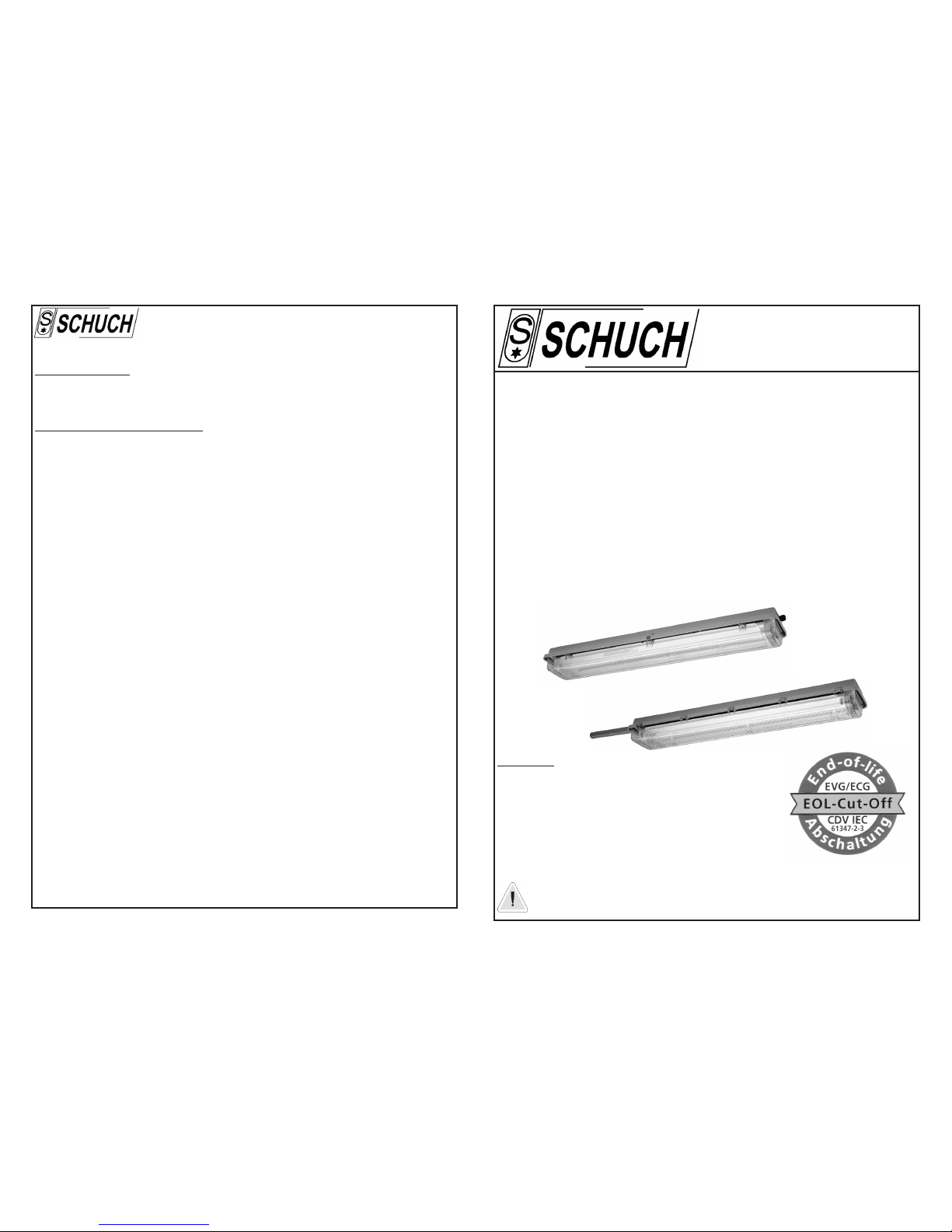
2. Standard Conformity
The explosion-proof light fitting of series e 152 ... is in conformity with the actual standards of technology.
It has been designed, manufactured and tested on the basis of EN 29001 (ISO 9001).
The emergency light fitting is in conformity with:
Directive 94/9/EC,
EN 50014:1997
EN 50017:1994
EN 50018:1994
EN 50019:1994
EN 50281-1-1:1998
EN 60529:1991+A1
Directive 89/336/EEC „Electromagnetic compatibility"
The light fitting e 152 ...
The test certificate is ready to be loaded down from our homepage - www.schuch.de - or we shall send it
on request.
has been approved for application in hazardous areas of zones 1 and 2 as well
as zones 21 and 22.
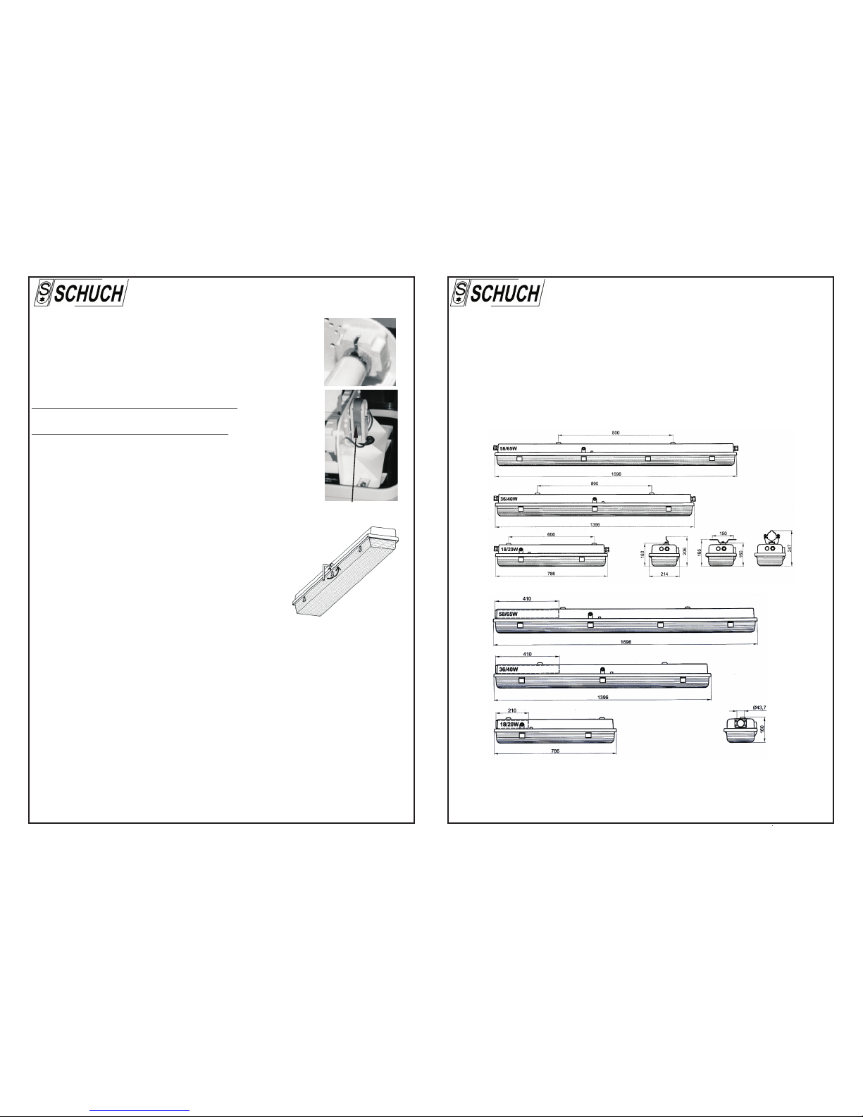
3. Technical Data
Explosion-proof light fitting for bi-pin fluorescent tubes with electronic control gear (ECG) and
disconnecting switch.
Series: e 152 ...
Explosion protection: xII 2 G EEx edq IIC T4 (standard version and version for pole mounting)
xII 2 G EEx eq II T4 (version without disconnecting switch)
xII 2 G EEx edq IIC T6 (version T6 only, with lamps 20 W of a 38 mm Ø
at an ambient temperature of +40°C max.)
xII 2 D T80°C
xII 2 D T90°C (special version of e 152 62 EVG and e 152 62 oS EVG
for an ambient temperature of +60°C max.)
Certification: PTB 97 ATEX 2223 (18 W or 20 W)
PTB 97 ATEX 2224 (36 W or 40 W)
PTB 97 ATEX 2225 (58 W or 65 W)
Lamps: Fluorescent tubes with lamp base G13 according to IEC 81
18 W, 36 W and 58 W, of a 26 mm Ø
20 W, 40 W and 65 W, of a 38 mm Ø
Rated voltage/frequency: 220 - 240 V ±10% AC, 50 - 60 Hz
198 - 254 V DC (operation of only one lamp in version e 152 .. ZB)
Insulation class: I
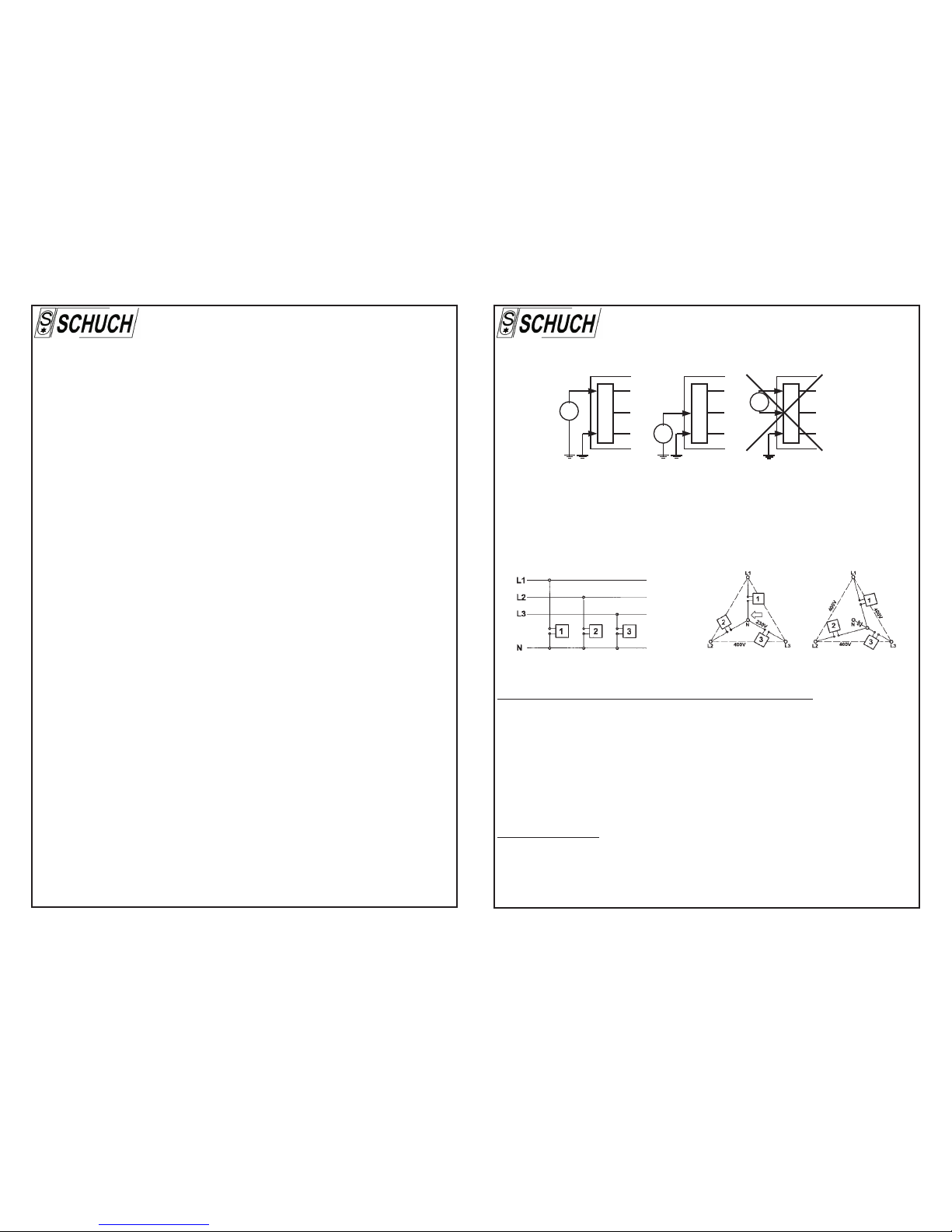
6.7 Insulation measurement
For measuring the insulating resistance the test voltage must be put on between the outer conductor and
the earth conductor or between the neutral conductor and the earth conductor only.
After finishing the insulation test a correct connection of the conductor between the mains and the light
fitting must be redone. Before starting operation the connection of the neutral conductor must be safe for
avoiding any damage whatsoever of the electronic ballast caused by any inadmissible excess-voltage in
case of an unbalanced mains load (see section 6.8).
correct incorrect
luminaire
with ECG
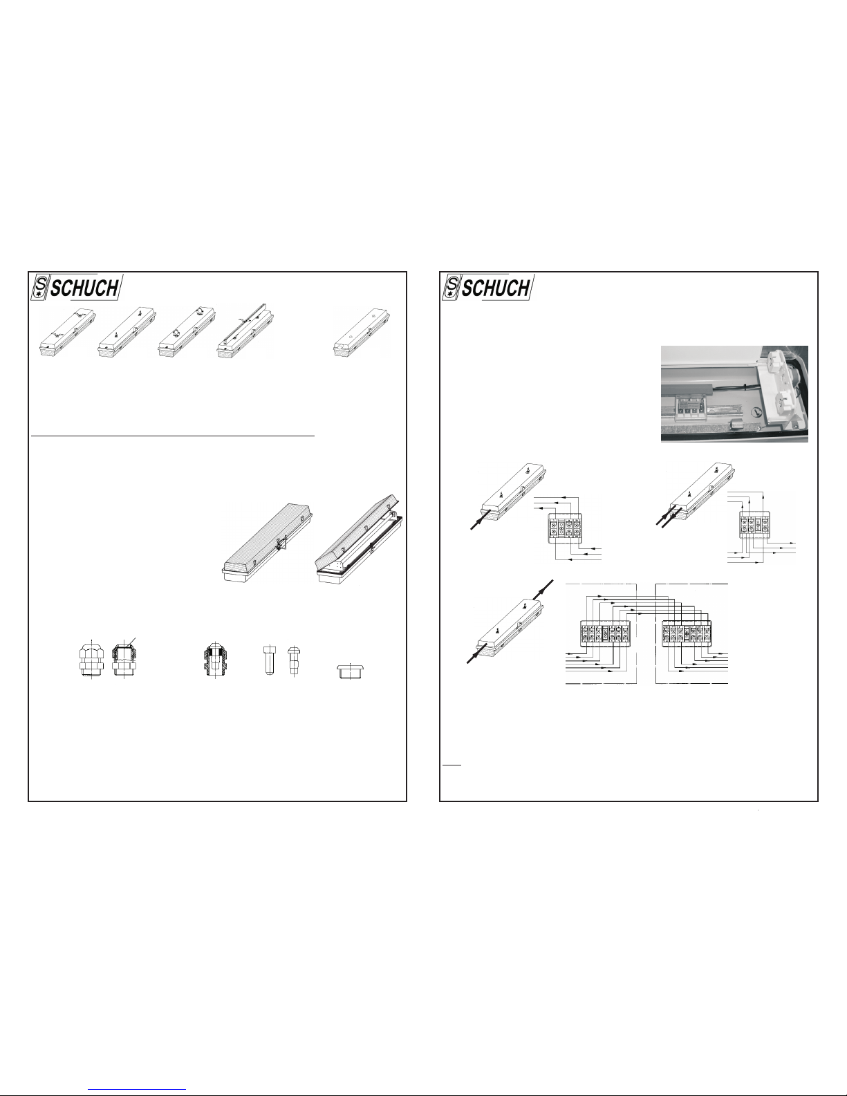
6.8 Electronic control gears (ECG) in three phase operation
The diagram shows the wiring for luminaires or luminaire groups in 3-phase circuits and with a common neutral
conductor N.
If the common neutral conductor is interrupted and voltage is present, then luminaires or groups of
luminaires may be exposed to unacceptably high voltages and consequently the electronic control gears
(ECG) may be destroyed.
N
test
U L
PE test
U
N
L
PE
test
U
N
L
PE
7. Maintenaince
Attention: Any repair, reconditioning and maintenance work on explosion-proof lighting fittings has
to be carried out by skilled electricians only!
The generally accepted rules of the technical side, the national safety standards and
especially the determinations of IEC 60079-14 and IEC 60079-17 for maintenance of
explosion-proof equipment must be observed.
If using the light fitting in areas with combustible dust, EN 50281-1-2 must be observed in
addition!
Please pay attention to the following in case of application in dusty atmospheres:
Dust deposits have got thermal insulation characteristic features i.e. the surface temperature of the
luminaire is getting higher in relation with the rising thickness of a dust layer (see the curve illustrated
in EN 50281-1-2). Consequently, it is a must that any dust deposits are regularly removed from the
lighting fitting so that any dust layers can never exceed a 5 mm thickness.
They must be well trained with regard to
operating explosion-proof products.
Service on the light fitting:
electronic control gear.
According to the relevant regulations explosion-proof light fittings need regular maintenance.
Especially components which are important for the Explosion Category have to be carefully checked.
For this reason you must carefully check:
- the condition of the lampholders and of the
- housing and cover for any possible cracks and other kind of damages.
- the efficiency of the gasket, i.e. you have to pay attention to the fact that all the hooks of the locking
system are internally touching the diffuser and that there is a uniform contact between the diffuser and