Schuch nD8611 L02 W Series User manual

!
o
Operating Instructions
Explosion-proof LED-Emergency Light Fitting
with built-in battery
Series
nD8611 L02/. W
The safety of people and equipment in hazardous areas depends on the
observance of all safety standards. Exact knowledge of all applicable
regulations and standards is mandatory for installation, maintenance and
repair of explosion proof equipment, especially
the determinations of IEC/EN 60079-14 and IEC/EN 60079-17 for the
maintenance of explosion-proof appliances
the generally accepted rules of technology
the national health and safety standards
the safety instructions of these operating instructions
the characteristic data on the type plate and the instruction plates

10/2022•L-01510-4-09 2
1. Safety Instructions
Mounting and installation must be done in accordance with the respective regulations.
The light fitting must be protected against overvoltage, over currents, short circuits and other
electrical failures.
The light fitting must be operated in an undamaged condition only.
The light fitting may only be opened if it has been disconnected from the mains supply completely.
It is allowed to open the light fitting in a non-explosive (non hazardous) atmosphere only.
The non-stationary use of the light fitting as well as any other inappropriate usage is prohibited.
The operation of the light fitting is allowed within its assessment thresholds only.
In regard to the minimum and maximum admissible ambient temperature potential sources of cold
and heat (e.g. direct heat or solar radiation, cooling units) have to be considered.
If the light fitting is subject to a special application that is influenced chemically, mechanically,
thermically or electrically or if the light fitting will be subject to any kind of vibrations, it is highly
recommended to consult the Adolf Schuch GmbH before starting the installation.
In areas where there is a high risk of mechanical danger, the light fitting must be protected by
proper measures.
Every structural modification will cause dangerous situations and consequently the certification of
this light fitting will be null and void.
Caution - Risk of electrostatic discharge!
Fitting to be cleaned with damp cloth only!
In areas with risk of accidental electrostatic charge (e.g. by passing by) the light fitting must
be protected by appropriate measures.
The light fitting is not allowed to be installed in process areas where strong electrical fields
may occur (i.e. HV Sparkling Electrodes or Particle Streams). Reason is to avoid any
electrostatic charge of the light fitting itself.
The filling level of the connection cable should be quite high for avoiding any air penetrating the
inside of the light fitting through the cable.
Applying an explosion-proof breathing gland for pressure compensation is not allowed.
Replace damaged parts by original spare parts from the Adolf Schuch GmbH only.
The LED-modules of this light fitting must be replaced by A. Schuch GmbH, by a service technician
who is instructed from Schuch or by any other person with equivalent qualification only.

10/2022•L-01510-4-09 3
!
2. Operating Advice
Because of the chemical resistance use only a damp cloth for cleaning the light fitting. If necessary
with a mild and solvent-free cleaning agent.
When using the light fitting outdoors, we recommend the use of a weatherproof roof to protect the
light fitting from the direct effects of the weather.
Any application of the light fitting that is incorrect or even forbidden will lead to the fact that the
manufacturer's warranty is lost.
LED are sensitive electronic components. Please ensure that the LED are protected against
mechanical and electrostatic attacks whenever the light fitting is open. For this reason the LED
must not be touched either.
Due to harmful gases and other corrosive substances (e.g. ammoniac, sulphur- or chlorine
compounds) it may come to damages of the LEDs. Depending on the substance, the concentration,
the temperature and the dwell time, damages up to total black-out are possible. This may occur
also to fittings with high degree of protection. The suitability of the light fitting for the respective
application can only be checked by running a test at site.
The light fitting has an additional Ex cable gland, which is locked by a closing plug and which is
designed as a Test port to run the test for restricted breathing (see section 5.3, Testing the
restricted breathing).
The Ex cable gland with closing plug, which is designed as a Test port, must
not be used for cable entry!
The operation of this light fitting is only allowed if the Ex cable gland, which is
designed as a Test port, is installed and locked with the provided closing plug!
2.1 Automatic Tests
According to EN 62034 the emergency light unit automatically checks the function and operating
period of the fitting during the emergency operation. Running functional- and operating period test are
indicated by a blinking green Signal-LED.
Commissioning test
To avoid discharging of the battery and misinterpretation of the LED signals during the installation
phase the internal set-up process of the emergency unit starts only when there was an uninterrupted
mains power supply for 5 days. Within the following 28 days the emergency electronic unit will conduct
the internal commissioning test.
Functional test
During the functional test the function of the emergency electronic unit, the emergency battery and the
LED are being checked by the emergency electronic unit. The test cycle will last approx. 5 sec. and
will be carried out once a week. The first functional test starts one week after commissioning test has
happened.
Operating period test
During the operating period test the emergency electronic unit is testing the capacity of the emergency
battery. Operating period tests will take place every year. The first test starts one year after the
commissioning test has happened.
If necessary the operating period test can be initiated manually at any point in time. This can be done
by interrupting and restoring the mains supply (e.g. by means of an up-stream fuse) for 5 times within
60 seconds.

10/2022•L-01510-4-09 4
2.2 LED-Signals
The built-in two-colored Signal-LED (red/green) does show the working condition and the error state of
the fitting. The following states are possible:
green permanent: Normal operation, the emergency battery is being charged
green blinking fast: Functional period test is running
green blinking slow: Operating period test is running
red permanent: LED failure
red blinking fast: Battery charging failure
red blinking slow: Insufficient capacity of the battery
green and red off: Emergency mode
2.3 Later application of a pictogram
If the light fitting is subsequently provided with a pictogram, on it`s type plate a "G" must be written in
the allowed space (see figure) with a water-resistant, light-resistant pin (for example: permanent
marker):
3. Technical Data
Series: nD8611 L02/. W
Explosion-proof LED-Emergency Light Fittings for operating in hazardous
areas of zones 2 and 22.
Explosion protection: oII 3 G Ex nR IIC T4 Gc
oII 3 D Ex tc IIIC T80 °C Dc
Certification: SH 14.8611
Rated voltage: 220...240 V AC; 50/60 Hz
Isolation class: I
Ingress protection: IP65
Ambient temperatur: 0 °C ... +30 °C (maintained operation)
0 °C ... +40 °C (non-maintained operation)
Energy efficiency class: This light fitting contains a light source of the energy efficiency class: C
Power consuption: ca. 5 W
Locking: 2 screws M4x8
Operation position: in any direction
Cable entry: The built in Ex cable gland with thread size M20 x 1.5 only!
(spare-part-no. 90120 9008)
Sealing range: 8 - 13 mm
Torques: Connection thread 2,3 Nm; Pressing screw 1,5 Nm
(Ex cable gland with closing plug = Test port)
or an Ex cable gland with an equivalent flat seal approved by the
manufacturer or in accordance with national regulations for the types of
protection nR and tc.
Housing bore: 20.3 mm +0.2/-0; wall thickness: 1.7 mm
Test port: Ex cable gland with closing plug (spare-part-no. 90122 9001)

10/2022•L-01510-4-09 5
Connection per terminal: Ampacity: 16 A max. (At maximum current load, a cross section of
2.5 mm² is required)
Screw terminal: Clamping range: 1 x 0.75 - 2.5 mm² (solid core or stranded)
1 x 1,5 - 2,5 mm² (flexible)
Required stripping length: 7 –7.5 mm
Torque of terminal screw: 0.5 Nm
Screwless terminal: Clamping range: 2 x 0.75 - 2.5 mm² (solid core or
stranded)
2 x 1.5 - 2.5 mm² (flexible)
Req. stripping length: 8 mm (conductor 0.75 - 1.0 mm²)
9 mm (conductor 1.5 - 2.5 mm²)
Possible number of
light fittings per circuit
breaker*:
*) Typical values; possible deviations depending on make, cable impedance and temperature
Rated luminous flux: 100%
Emergency battery: 1-hour version: Type 8620 (spare-part-no. 90222 9026)
3,6 V, 2,2 Ah (battery pack composed of 3 NiMh-cells)
3-hour version: Type 8621 (spare-part-no. 90222 9027)
6 V, 2,2 Ah (battery pack composed of 5 NiMh-cells)
Dimensions:
(all measures in mm)
Special versions with the possibility for cable looping:
Equipotential bonding: Connection terminal for equipotential bonding on the outside of the light
fitting
Clamping range: 4 mm² max.
Torque of terminal screw: 2 Nm max.
Type
B 10 A
B 16 A
C 10 A
C 16 A
nD8611 L02/. W
81
130
135
221

10/2022•L-01510-4-09 6
!
!
!
!
4. Installation
The safety of this light fitting is only guaranteed as long as it is operated within its
assessment threshold. Installation and maintenance must be done in accordance with
the respective regulations!
The installation of explosion-proof light fittings must be done by Ex-skilled electricians
only!
In regard to the minimum and maximum admissible ambient temperature potential
sources of cold and heat (e.g. direct heat or solar radiation, cooling units) have to be
considered!
If there is a risk of accidental electrostatic charge the light fitting must be protected by
appropriate measures!
The application of this light fitting in an explosive dust atmosphere is depending on the
properties of the surrounding dust. Please ensure that there will be an adequate
difference between the maximum surface temperature of the fitting and the glowing and
the ignition temperature of the respective dust!
Applying an explosion-proof breathing gland for pressure compensation is not allowed!
4.1 How to open the light fitting
The light fitting may only be opened if it has been disconnected from the mains supply
completely!
It is allowed to open the light fitting in a non-explosive (non hazardous) atmosphere
only!
Please ensure that the LED are protected against mechanical and electrostatic attacks
whenever the light fitting is open. For this reason the LED must not be touched either!
Loosen the two captive screws out of the diffuser.
Lift the diffuser from the housing.
4.2 Electrical connection
The filling level of the connection cable should be quite high for avoiding any air
penetrating the inside of the light fitting through the cable!
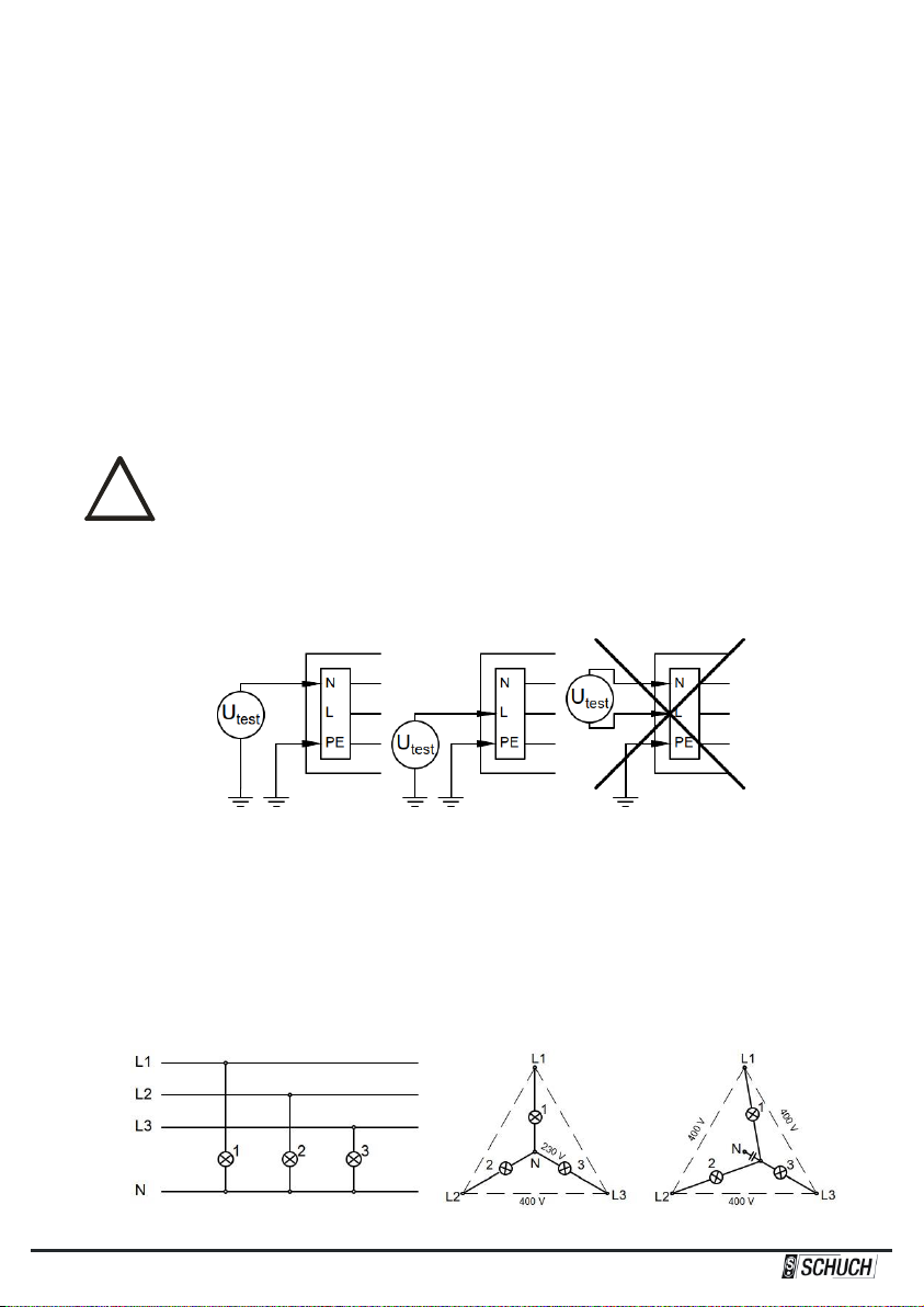
The Test port for restricted breathing (Ex cable gland with closing plug, see
illustration in section 3, Technical Data), must not be used for cable entry in any
case!
After mounting the light fitting housing insert the connection cable through the Ex cable gland. An
inlaid dust protective disc, if existing, must be removed before.
Fasten the pressing screw of the Ex cable gland (Torque see section 3, Technical Data).
Outside the light fitting appropriate measures (e.g. pull relief clips) must be taken to
protect the connection cable from twist and it must be ensured that no tensile forces react
on the wiring and the Ex cable gland!
The diameter of the connection cable must correspond to the sealing range of the Ex
cable gland (see section 3, Technical Data)!
Ex cable glands, which are not used, must be closed with the enclosed closing plug (see
section 3, Technical Data)! An inlaid dust protective disc, if existing, must be removed
before.
The conductors must not be damaged when skinning resp. stripping the cable!
When stripping the cable special attention needs to be paid to the correct length of the
conductor end sections (see section 3, Technical Data)!

10/2022•L-01510-4-09 7
!
!
!
Connect the conductors of the connection cable to the right terminals as per marking.
Tighten connection screws - including those of the unused terminals (Torque see section 3,
Technical Data).
It is important to ensure that the bare conductor is fully inserted into the terminal and that
no cable insulation is clamped!
Modes of operation
Non-maintained operation:
The light fitting switches on automatically in case of a mains failure.
The direct phase (L1) will be connected to connecting point L1 as mains supply monitor. Connecting
point L1’ will not be connected.
Maintained operation:
The light fitting switches on automatically and it may be used as a standard light fitting if mains voltage
is on.
The same direct phase (L1) will be connected to connecting point L1 as mains supply monitor and to
connecting point L1' as switched phase.
Connecting the emergency battery
In addition to the mains also the emergency battery must be connected. This is being done by
connecting the plug with the red battery cable to the positive terminal of the battery. If mains voltage is
available the battery is charged and the LED is lighting green.
Only connect/disconnect the emergency light fitting and emergency battery
in a non-explosive atmosphere.
4.3 Replacing LED circuit board and emergency light unit
Replacement of LED board and emergency light unit has been described in the separate instructions
which can be found attached to the spare parts to be supplied.
4.4 How to close the light fitting
Reput the diffuser back onto the housing.
Screw the screws of the diffuser into the housing.
After closing the light fitting please make sure that the gasket is correctly sealing it!

10/2022•L-01510-4-09 8
!
5. Commissioning
Before commissioning this explosion-proof lighting fitting please check and ensure that:
the light fitting has been installed according to the regulations.
the Ex cable glands are securely fixed in the housing and the closing plug is installed in a proper
manner (Torques see section 3, Technical Data).
the pressing screw of every Ex cable gland is tightened with the required torque (Torques see
section 3, Technical Data).
the connection cable has been firmly installed and is not subject to any tension whatsoever.
the bare conductor is fully inserted into the terminal and that no cable insulation is clamped.
the terminal screws of the connection terminals are firmly tightened (Torques see section 3,
Technical Data).
the light fitting is closed correctly.
all gaskets are effective.
the light fitting is not damaged whatsoever.
The restricted breathing of the light fitting is condition for its safe operation!
Therefore, prior to commissioning, check the restricted breathing in accordance with
section 5.3.
5.1 Isolation measurement
For measuring the isolating resistance the test voltage must be put on between the outer conductor
and the earth conductor or between the neutral conductor and the earth conductor only.
After finishing the isolation test the conductor between the mains and the light fitting must be
reconnected safely. Before starting operation the connection of the neutral conductor must be safe for
avoiding any damage whatsoever of the electronic control gear caused by any inadmissible excess-
voltage in case of an unbalanced mains load. (see section 5.2)
5.2 Emergency light unit in 3-phase-operation
The diagram shows the wiring for light fittings or light fitting groups in 3-phase circuits and with a
common neutral conductor N. If the common neutral conductor is interrupted and voltage is present,
then light fittings or groups of light fittings may be exposed to unacceptably high voltages and
consequently the emergency light unit may be destroyed.
Light fittings with emergency light unit OK fault

10/2022•L-01510-4-09 9
!
5.3 Testing the restricted breathing
The test of the restricted breathing of the light fitting must be carried out after installation and at regular
intervals. For this purpose, the light fitting is provided with a Test port, which consists of an Ex cable
which is locked by a closing plug.
For testing, a negative pressure is to be generated in the light fitting via the Test port. Under constant
temperature conditions, the vacuum must exceed a predetermined minimum value after a specified
waiting time has elapsed.
According to EN/IEC 60079-15:2019, section 12.2.2.1.2, three test methods can be used:
Method 1
Method 2
Method 3
Underpressure
at the beginning of the test
3 kPa
(30 mbar)
0,3 kPa
(3 mbar)
0,3 kPa
(3 mbar)
Waiting time
14 s
14 s
90 s
Minimum underpressure
after waiting time has elapsed
2,7 kPa
(27 mbar)
0,27 kPa
(2,7 mbar)
0,15 kPa
(1,5 mbar)
After completing the test, make sure that the closing plug is inserted back into the Ex
cable gland and the pressing screw is tightened properly (Torque see section 3,
Technical Data).

10/2022•L-01510-4-09 10
!
!
!
!
6. Maintenance
6.1 Repair- and maintenance works
The light fitting may only be opened if it has been disconnected from the mains supply
completely!
It is allowed to open the light fitting in a non-explosive (non hazardous) atmosphere
only!
For applications in dusty atmospheres the light fitting must be cleaned before opening!
Ensure that no dust can get into the light fitting when it is open!
Working on the inner parts of the light fitting is allowed in non hazardous atmosphere
only!
Replace damaged parts by original spare parts from the Adolf Schuch GmbH only!
Spare Parts:
For spare parts inquiries, in addition to the complete type designation of the light fitting, the serial
number of the light fitting must be stated. The serial number is printed on the type plate of the light
fitting –on the bottom left.
6.2 Cleaning the light fitting
At the plastic parts of the light fitting there is a danger of ignition due to electrostatic
charging! For cleaning the housing and cover outside and inside and for cleaning internal
plastic components use only cold or lukewarm water (if necessary with a mild cleaning
agent) together with a viscose sponge or a soft fibrous-free cloth!
Pay attention to the following in case of application of this light fitting in dusty atmospheres:
Dust deposits show heat-insulating properties and thus reduce the service life of the light fitting. It is
necessary to clean the fitting from dust regularly. In case the dust layer may be higher than 5 mm it
must be ensured that the surface temperature of the light fitting does not exceed the maximum
permissible surface temperature of the specific dust considering the thickness of the dust layer. The
dust layer must not exceed 50 mm at any time.
6.3 Regular maintenance work
Follow the instructions of section 6.1!
Explosion-proof light fittings need regular maintenance according to the national rules of the country
they are installed. Especially components which are important for the Explosion Category have to be
carefully checked. Therefore it must to be checked very carefully:
diffuser, housing and gaskets for any kind of damages.
effectiveness of gasket betweeen glass and housing.
the correct installation and tightness of Ex cable glands and closing plug (Torques see section 3,
Technical Data).
all parts of plastic inside the light fitting to attend to colour change, deformation and damaging.
the tight fit of the conductor and the condition of the cable insulation.
that the light fitting is closed correctly and the gasket is effective.
The restricted breathing of the light fitting is condition for its safe operation and must
therefore be regularly checked under particular consideration of its operating conditions
(see section 5.3, Testing the restricted breathing)!

10/2022•L-01510-4-09 11
!
!
The maintenance of the fitting as an emergency light fitting has to be done following the actual
international and national regulations.
6.4 How to replace the emergency battery
The battery needs to be replaced if the slow blinking red Signal-LED is indicating a battery capacity
failure.
Only original batteries as per the battery type plate must be used for replacing the
battery!
Working on the inner parts of the light fitting is allowed in non hazardous atmosphere
only –see section 6.1!
The battery must be charged via the lighting fitting only!
After replacement of the battery and switching on the mains voltage the emergency light unit will
initiate the commissioning test as soon as there was an uninterrupted mains power supply for 5 days
(see section 2.1). Functional test and operating period test will take place as described in section 2.1.
6.5 Environmental advice
This device has got an accumulator which contains ecologically dangerous materials.
There is a particular designation for this purpose. The people operating this device
are obliged by law to return accumulators which have become waste and which
contain any pollutant materials to organizations which are in the hands of the vendors
or waste disposal holders being under public law.
6.6 Placing the fitting out of operation
To avoid unnecessary discharging of the battery the battery must disconnected from the emergency
light unit when putting the fitting out of operation. To do so the plug must be disconnected from the
positive terminal of the battery.
To avoid any damages the battery should not be stored for more than 6 months
without being re-charged periodically!

10/2022•L-01510-4-09 12
The test certificates are ready to be loaded down from our homepage - www.schuch.de - or we shall send it
on request.
Misprints, modifications and errors are excepted
Table of contents
Other Schuch Lighting Equipment manuals