Schuch nD867.12L Series User manual

o
!
Adolf Schuch GmbH
Lichttechnische Spezialfabrik
Mainzer Str. 172, D-67547 Worms am Rhein
Postfach (P.B.) 2145, D-67511 Worms
Phone: +49 6241/4091-0 Internet: www.schuch.de
Telefax: +49 6241/4091- 29 E-Mail: info@schuch.de
- Operating Instructions
Explosion-proof LED Emergency Light Fitting
of series
nD867. 12L .. / . / .
The safety of people and equipment in hazardous areas depends on the
observance of all safety standards. Exact knowledge about all applicable
regulations and standards is mandatory for installation maintenance and
repair of explosion proof equipment, especially
the determinations of IEC/EN 60079-14 and IEC/EN 60079-17 for
maintenance of explosion-proof appliances
the generally accepted rules of the technical side
the national rules for prevention of accidents and for safety standards
the safety instructions of these operating instructions
the characteristic data on the type plate and the instruction plates

2 L-01394-4-05
1. Safety Instructions
Mounting and installation must be done in accordance with the respective regulations.
The light fitting must be protected against overvoltage, overcurrent, short circuits and other
electrical failures.
The light fitting must be operated in an undamaged condition only.
It is allowed to open the light fitting in a non-explosive (non hazardous) atmosphere only.
The non-stationary use of the light fitting as well as any other inappropriate usage is prohibited.
The operation of the light fitting is allowed within its assessment thresholds only.
In regard to the minimum and maximum admissible ambient temperature potential sources of cold
and heat (e.g. direct heat or solar radiation, cooling units) have to be considered.
If the light fitting is subject to a special application that is influenced chemically, mechanically,
thermically or electrically or if the light fitting will be subject to any kind of vibrations, it is highly
recommended to consult the Adolf Schuch GmbH before starting the installation.
Every structural modification will cause dangerous situations and consequently the certification of
this light fitting will be null and void.
Caution - Risk of electrostatic discharge! Fitting to be cleaned with damp cloth only!
In areas with risk of accidental electrostatic charge (e.g. by passing by) the light fitting must be
protected by appropriate measures.
The light fitting is not allowed to be installed in process areas where strong electrical fields may
occur (i.e. HV Sparkling Electrodes or Particle Streams). Reason is to avoid any electrostatic
charge of the light fitting itself.
Replace damaged explosion-proof parts by original spare parts from the Adolf Schuch GmbH only.
The LED-modules of this light fitting must be replaced by A. Schuch GmbH, by a service technician
who is instructed from Schuch or by any other person with equivalent qualification only.

L-01394-4-05 3
2. Operating Advice
Because of the chemical resistance use only a damp cloth for cleaning the light fitting. If necessary
with a mild and solvent-free cleaning agent.
Against penetration of humidity into the light fitting a special explosion-proof breathing gland is often
quite effective. It is allowed to use a breathing gland which is released by the Adolf Schuch GmbH
only. If using a breathing gland please observe the general informations of it's operation
instructions.
Any application of the light fitting that is incorrect or even forbidden will lead to the fact that the
manufacturer's warranty is lost.
Through-wiring in lighting model nD867. 12L60 / . / . without battery box lowers the permitted
ambient temperature of the light from +40 °C (without through-wiring) to +35 °C (with through-
wiring). Please also refer to the corresponding instructions on the type plate of the light fitting.
Opening the LED compartment is allowed for repair work only.
LED are sensitive electronic components. Please ensure that the LED are protected against
mechanical and electrostatic attacks whenever the light fitting is open. For this reason the LED
must not be touched either.
Due to harmful gases and other corrosive substances (e.g. ammoniac- sulphur-, or chlorine
compounds) it may come to damages of the LEDs. Depending on the substance, the concentration,
the temperature and the dwell time, damages up to total black-out are possible. This may occur
also to fittings with high degree of protection. The suitability of the light fitting for the respective
application can only be checked by running a test at site.
Due to a high inrush current when switching on the light fitting, the number of light fittings which can
be connected to a single fused circuit is limited (Possible number of light fittings per circuit breaker
see Chapter 3, Technical Data).
All DALI dimmable light fittings have two additional terminals marked „DA“. Lines to the control
terminals must be mains voltage proof.
LED modules are built up of a series connection, which itself is built up of parallel connections of
single LEDs. Failures of LEDs do not necessarily lead to a change in the power consumption,
which is recognized by the emergency light unit.
Version with battery box
Version
without battery box

4 L-01394-4-05
2.1 Use at low temperatures
The safety of the light fitting is warranted between -30°C up to +40°C/+55°C.
At temperatures below 0 °C, it must be taken into account that the emergency battery will take longer
to charge and the operational life of the emergency lighting mode will be reduced. Testing the duration
of the battery life in lower ambient temperatures can therefore lead to a misleading result.
The battery life test should be repeated manually at a more appropriate time (please refer to the
section about operational life testing in Chapter 2.2).
2.2 Automatic test of the emergency light unit
The functionality of the light fitting and the operational life in emergency lighting mode is tested
automatically by the emergency light unit at specified intervals. A blinking green light is emitted by the
signal LED while the test is being carried out.
Functionality test
Functionality tests are carried out at 7 day intervals and last one minute.
The first test of functionality is carried out one hour after the light fitting has been setup. Before this can
happen, it is necessary to separate the emergency light unit built into the light fitting from the mains
power supply before switching on the power, and the emergency battery must have been charged
continuously for one hour.
Operational life test
During the operational life test, the emergency light unit checks whether the capacity of the emergency
battery is sufficient for the indicated nominal operating time should the emergency light being required.
For the operational life test to be carried out, the emergency battery must be fully charged and
connected. For special versions with the option to deactivate the emergency light function, the remote
cutoff switch must also be closed.
Automatic operational life tests:
The first operational life test carried out automatically by the emergency light unit takes place at
random within a period of 5 to 28 days after the light fitting has been setup. All further automatic
operational life tests are then carried out at 52 week intervals, so long as the energy supply to the
emergency light unit was not interrupted during this period.
A complete interruption of the energy supply to the emergency light unit occurs when the outage of the
power supply exceeds the specified nominal operating time for the emergency light.
Reconnecting the power supply to the emergency light unit after a complete interruption will lead to a
new setup procedure of the emergency light with a subsequent operational life test between 5 and 28
days later.
Should a fault in the battery capacity be indicated before a complete interruption of the power supply to
the emergency light unit, a operational life test will be carried out within 24 hours of reconnection to the
power supply.
If the prerequisites stated above for carrying out an automatic operational life test are not satisfied, the
test will be deferred until these requirements are fulfilled.
Automatic operational life tests that could not be completed successfully will be repeated once after 60
hours, subject to the same prerequisites stated above.
Manual operational life tests:
Operational life tests can be triggered manually in 2 ways. Models with battery box can be triggered
manually in 3 ways:
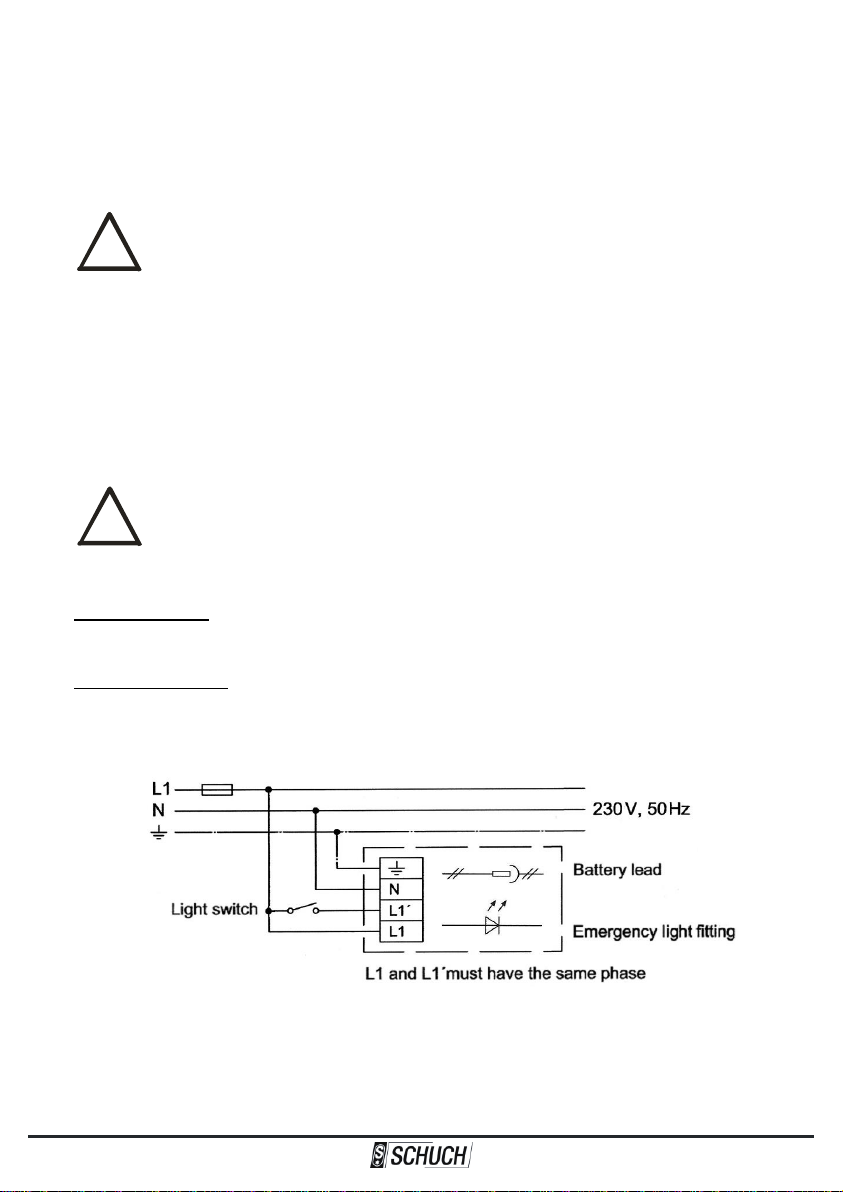
1. By switching the power supply off and on at the L1 terminal.
2. By switching the supply on and off at the L1`terminal.
Switch the power supply at the L1 terminal resp. the supply at L1' terminal off and on again 5 times.
Leave at least 2 seconds between each switch.
In both cases, the sequence of switches must be completed within 60 seconds.
Under the above mentioned preconditions, after a correctly performed switching sequence at L1'
terminal, an operational life test is immediately initiated.
If the switching sequence is correctly carried out on L1 terminal, an operational life test is initiated after

L-01394-4-05 5
!
the time that is required to fully charge the battery after the switching sequence.
If the switch sequence has not been carried out correctly, or the aforementioned requirements have
not been satisfied, the operational life test will not be conducted.
If there was an error in the switching procedure, the entire switch sequence can only be repeated after
60 seconds have elapsed.
The points at which regular operational life tests are carried out are not affected by conducting a
manual test using either of these methods.
3. For models with a battery box by means of disconnecting and reconnecting the battery:
Open and close the lid of the battery box twice within a 60-second period. Opening and closing the
case must occur within 10 seconds of each other.
If this procedure is done correctly, immediately after the battery box is closed for the second time, the
signal LED will display an acknowledgement light. The five-second long red-green acknowledgement
light confirms that a operational life test will be conducted 12 hours later.
Should a battery capacity fault be present when the acknowledgement light is displayed, more
operational life tests will then be carried out at 52 week intervals. If no fault was detected in the battery
capacity, the interval until the next regular operational life test is unaffected.
During the functionality and operational life tests, the light fitting will switch on even if it
was previously switched off!
2.3 Ascertainable faults and reset of the display
LED failure
If a fault in the LED is detected by the emergency light unit during a functionality test, the LEDs will be
switched off and the fault will be indicated by a permanent red light on the signal LED.
An LED fault will be reset if a functionality test produces a positive result or if the emergency light unit
is completely separated from the battery and power supply.
Battery capacity failure
If the emergency light unit detects during a operational life test that the capacity of the emergency light
battery is insufficient to maintain the light fitting for the nominal operating time in the case of an
emergency, the signal LED will display a red blinking light.
An emergency battery that no longer has sufficient capacity must be replaced immediately (see
Section 6.3).
The display indicating a fault in the battery capacity can only be reset by means of a successful
operational life test.
Battery contact failure
When the electrical connection between the emergency light unit and the emergency battery is broken,
the signal LED will display a red flashing light.
A battery contact failure and its signal are automatically reset as soon as the connection between the
emergency light unit and the battery is re-established.

6 L-01394-4-05
!
2.4 LED-Signals
The two-colored LED (red/green) which is integrated in the reflector of the light fitting does show the
working condition and the error state of the fitting.
The following states are possible:
Continuous green light: Permanent charging mode –
light fitting at mains operation,
the emergency battery is being charged
Blinking green light: Functionality test or operational life test (check of the
capacity of the battery)
Alternating green and red light: Light fitting deactivated / remote cutoff switch
Red flashlight: Battery failure –
the battery is not connected to the emergency
light unit
Blinking red light: Insufficient capacity of the battery –
the battery must be replaced
Continuous red light: LED failure
Acknowledgement light: Indicator signal in lighting models with battery box that
battery change was successfully carried out
means: red light for ½ second, green light for ½ second
and no light for ½ second
2.5 Instructions for special versions with remote cutoff switch
Special versions of these lighting fixtures are equipped to be connected to a remote cutoff switch.
Through a remote cutoff switch (isolated switching contact) it is possible to remove the light fitting from
operation, e.g. during maintenance.
The remote cutoff switch must be closed during normal operation of the special light fitting.
If the remote switch is open, there will be no emergency lighting in the case of a power outage.
A change to the switch position of the remote cutoff switch is only indicated if the fixture is connected
to a power supply.
If no power supply is present, when the remote switch is closed (resetting the
deactivation) the light fitting will not enter emergency lighting mode!
Functionality and operational life tests that are due to be carried out when the remote cutoff switch is
deactivated will be postponed until the deactivation is reset, and will be conducted when the necessary
requirements for the respective test are satisfied.
The interval of functionality and operational life tests are not affected by deactivating the light fitting.

L-01394-4-05 7
3. Technical Data
Series: nD867. 12L .. / . / .
│ │ └─ Capacity of emergency battery
│ └─ Nominal operating time in case of emergency
└─ Index of luminous flux
Explosion-proof LED Emergency Light Fitting for operating in hazardous
areas of zones 2 and 22.
Explosion protection: oII 3 G Ex ec IIC T4 Gc (Version without battery box)
oII 3 G Ex db ec IIC T4 Gc (Version with battery box)
oII 3 D Ex tc IIIC T80 °C Dc
Certification: SH 16.8670
Rated voltage: 220…240 V AC; 50...60 Hz
Switching from mains to battery operation at approx. 180 V
Switching from battery to mains operation at approx. 195 V
Dimensions:
(all measures in mm)
Version with battery box:

8 L-01394-4-05
Isolation class: I
Ingress protection: IP66 (When using an Ex-breathing gland see Section 2)
Ambient temperatur: Version without battery box: -30 °C ... +35 °C / +40 °C (see type plate)
Version with battery box: -30 °C ... +55 °C
Power consumption: The power consumption of the LED is dependent on production fluctuations
as well as on the service temperature.
This is why just reference values can be given as follows:
nD867. 12L42 / . / . : 33 W
nD867. 12L60 / . / . : 48 W
Cable entry: Cable glands with thread size M25 x 1.5
(if supplied) Sealing range: 7 - 17 mm (for 10 - 17 mm remove the small sealing ring)
Torques: Connection thread 3 Nm; Pressing screw 2 Nm
Torque of locking screw: 5 Nm
See information label on the front page when having special versions!
Connection per terminal: Ampacity: 16 A max.
Clamping range: 2 x 0.75 –2.5 mm² (solid core or stranded)
Required stripping length: 8 mm (conductor 0.75 –1.0 mm²)
9 mm (conductor 1.5 –2.5 mm²)
See information label on the front page when having special versions!
Locking: Clamp lockings (to be opened by hand) as well as one safety closure at
each side (to be opened with a suitable screw driver)
Operation position: in any direction - except upwards light output
Rated luminous flux: ca. 17% with nD867. 12L42 / . / .
ca. 13% with nD867. 12L60 / . / .
Possible number of
light fittings per circuit
breaker:
Spare battery: Version without battery box:
Type 89899695, 6 V, 1,6 Ah, NiCd;
1 hour emergency light time (standard version), special version see
type plate;
Art.-Nr. 90222 9030
Type 89895973, 6 V, 4 Ah, NiCd;
3 hours emergency light time (standard version), special version
see type plate;
Art.-Nr. 90222 9029
Version with battery box:
Typ 8020, 6 V, 1,6 Ah, NiCd;
1 hour emergency light time (standard version), special version see
type plate;
Art.-Nr. 90222 9023
Typ 2627, 6 V, 4 Ah, NiCd;
3 hours emergency light time (standard version), special version
see type plate;
Art.-Nr. 90222 9021
Type B
10 A
Type B
16 A
Type C
10 A
Type C
16 A
nD867. 12L ..
7
11
12
19

L-01394-4-05 9
!
!
4. Installation
The safety of this light fitting is only guaranteed as long as it is operated within its
assessment threshold. Installation and maintenance must be done in accordance with
the respective regulations!
The installation of explosion-proof light fittings must be done by Ex-skilled electricians
only!
In regard to the minimum and maximum admissible ambient temperature potential
sources of cold and heat (e.g. direct heat or solar radiation, cooling units) have to be
considered!
The application of this light fitting in an explosive dust atmosphere is depending on the
properties of the surrounding dust. Please ensure that there will be an adequate
difference between the maximum surface temperature of the fitting and the glowing and
the ignition temperature of the respective dust!
If there is a risk of accidental electrostatic charge the light fitting must be protected by
appropriate measures!
The light fitting must be mounted in the instructed operation position (see Chapter 3,
Technical Data)!
4.1 How to open the light fitting
Open clamp lockings by hand.
There is a safety closure at each
side, which can be opened with
a screw driver (3 –6 mm blade
size) only (see drawing). Safety closure
Remove the diffuser with the included reflector.

10 L-01394-4-05
!
!
4.2 Electrical connection
Screw the explosion-proof cable glands and explosion-proof locking screw supplied with the fitting
into the borings of the housing by using the lock nuts (Torques see Chapter 3, Technical Data).
After mounting the light fitting housing insert the connection cable through the explosion-proof cable
gland. An inlaid dust protective disc, if existing, must be removed before.
Fasten the pressing screw of the explosion-proof cable gland (Torque see Chapter 3, Technical
Data).
Outside the light fitting appropriate measures (e.g. pull relief clips) must be taken to
protect the connection cable from twist and it must be ensured that no tensile forces
react on the wiring and the cable entry!
The diameter of the connection cable must correspond to the sealing range of the
explosion-proof cable gland (see Chapter 3, Technical Data)!
Cable entries, which are not used, must be closed with the enclosed closure plug (see
Chapter 3, Technical Data)! An inlaid dust protective disc, if existing, must be removed
before.
The conductors must not be damaged when skinning resp. stripping the cable!
When stripping the cable special attention needs to be paid to the correct length of the
conductor end sections (see Chapter 3, Technical Data)!
Connect the conductors of the connection cable to the right terminals as per marking.
It is important to ensure that the bare conductor is fully inserted into the terminal and that
no cable insulation is clamped!
Modes of operation
Stand-by operation:
The light fitting switches on automatically in case of a mains failure.
Only the direct phase (L1) will be connected to connecting point L1 as mains supply monitor.
Maintained operation:
The light fitting switches on automatically and it may be used as a standard light fitting if mains voltage
is on.
The same direct phase (L1) will be connected to connecting point L1 as mains supply monitor and to
connecting point L1' as switched phase.

L-01394-4-05 11
!
!
!
Note for connecting armoured cable:
It is necessary to check back with the Adolf Schuch GmbH before installing other
explosion-proof cable glands or explosion-proof locking screws than the ones supplied!
Connecting an emergency battery
In its delivery state, there is no electrical connection between the emergency battery and the
emergency light unit.
The electrical connection between the battery and the unit can only be established or
broken in a non-explosive atmosphere!
If no power supply is present, even if the light fitting is connected to the emergency
battery, it will not enter emergency lighting mode!
The electrical connection between the emergency battery and emergency light unit should be
established as follows:
Version without battery box:
Attach the connector of the red battery cable leading to the emergency light unit to the positive pole
of the emergency battery.
Version with battery box:
Open the battery box by loosening the locking screws and flip open the lid.
Remove the protective cap from the connector of the battery cable.
Attach the connector of the battery cable to the socket in the battery box. Check the catch
mechanism of the plug connection.
Close the lid of the battery box and tighten the locking screws.
4.3 How to close the light fitting
Join diffuser with included reflector and housing together.
Hook the clamp lockings into the diffuser and fix it.
After closing the light fitting take care that the whole gasket is effective.
5. Commissioning
If a power supply is present, the battery connected to the emergency light unit will be charged. The
signal LED will indicate this state by means of a steady green light.
After the initial setup, the emergency battery must be charged for 12 hours. From a
physical point of view, the full capacity of the battery is only available after 3 or 4 charge-
discharge cycles.
If a battery contact failure is indicated despite an existing connection to a power supply and to the

12 L-01394-4-05
emergency battery, the emergency battery may be the cause, which might contain insufficient charge
to be charged in the potentially explosive atmosphere.
In this case, the emergency battery is to be removed as described in Section 6.3 and to be charged
separately from the light fitting. With a 6 V charging voltage and 80 mA charging current, a discharged
battery will be sufficiently charged within just 5 minutes for it to be reinserted into the light fitting, where
it can continue to charge.
Before commissioning this explosion-proof lighting fitting please check and ensure that:
the light fitting has been installed according to the regulations and in the allowed operating position.
the explosion-proof cable glands resp. explosion-proof locking screws are securely fixed in the
housing (Torques see Chapter 3, Technical Data).
the pressing screw of every explosion-proof cable gland is tightened with the required torque
(Torques see Chapter 3, Technical Data).
the connection cable has been firmly installed and is not subject to any tension whatsoever.
the bare conductor is fully inserted into the terminal and that no cable insulation is clamped.
the light fitting is closed correctly.
all gaskets are effective.
the light fitting is not damaged whatsoever.
5.1 Isolation measurement
For measuring the isolating resistance the test voltage must be put on between the outer conductor
and the earth conductor or between the neutral conductor and the earth conductor only.
After finishing the isolation test the conductor between the mains and the light fitting must be
reconnected safely. Before starting operation the connection of the neutral conductor must be safe for
avoiding any damage whatsoever of the electronic control gear caused by any inadmissible excess-
voltage in case of an unbalanced mains load. (see Chapter 5.2)
5.2 Emergency light unit in 3-phase-operation
The diagram shows the wiring for light fittings or light fitting groups in 3-phase circuits and with a
common neutral conductor N.
Light fittings with emergency light unit OK fault
If the common neutral conductor is interrupted and voltage is present, then light fittings or groups of
light fittings may be exposed to unacceptably high voltages and consequently the emergency light unit

L-01394-4-05 13
!
!
!
may be destroyed.
6. Maintenance
Explosion-proof light fittings need regular maintenance according to the national rules of the country
they are installed. Especially components which are important for the Explosion Category have to be
carefully checked. Therefore it must to be checked very carefully:
diffuser, housing and gaskets for any kind of damages
the correct installation and tightness of explosion-proof cable glands and explosion-proof locking
screws (Torques see Chapter 3, Technical Data).
all parts of plastic inside the light fitting to attend to colour change, deformation and damaging.
the tight fit of the conductor and the condition of the cable insulation.
that the light fitting is closed correctly and the gasket is effective.
The maintenance of the fitting has to be done following the actual international and national
regulations.
6.1 Cleaning the light fitting
Danger of ignition due to electrostatic charging at the plastic parts of the light fitting!
Only clean the inside of the glass and case of the light fitting (as well as its plastic parts)
with a damp cloth. For this only use cold or lukewarm water (if necessary with a mild
cleaning agent) together with a viscose sponge or a soft fibrous-free cloth!
Pay attention to the following in case of application of this light fitting in dusty atmospheres:
Dust deposits have got thermal insulation characteristic features. It is necessary to clean the fitting from
dust regularly. In case the dust layer may be higher than 5 mm it must be ensured that the surface
temperature of the light fitting does not exceed the maximum permissible surface temperature of the
specific dust considering the thickness of the dust layer. The dust layer must not exceed 50 mm at any
time.
6.2 Repair- and maintenance works
The light fitting may only be opened if it has been disconnected from the mains supply
completely!
It is allowed to open the light fitting in a non-explosive (non hazardous) atmosphere
only!
For applications in dusty atmospheres the light fitting must be cleaned before opening!
Ensure that no dust can get into the light fitting when it is open!
Replace damaged explosion-proof parts by original spare parts from the Adolf Schuch
GmbH only!
6.3 How to replace the emergency battery
Only original batteries as per the type plate on the battery must be used for replacing
the battery (see Chapter 3, Technical Data)!
Version without battery box:
Separate the emergency battery electrically and remove it from the light fitting (see Chapter 4.2
Section: Connecting an emergency battery).
Insert a new emergency battery and establish an electrical connection.

14 L-01394-4-05
If a battery capacity failure was indicated before the light fitting was switched off, a operational life test
will be carried out 24 hours after the power supply is re-established. The subsequent operational life
tests will be conducted at 52 week intervals.
If no battery capacity failure was indicated before the battery was changed, the interruption of the
energy supply to the emergency light unit will result in a operational life test between 5 and 28 days
later. The subsequent operational life tests will be conducted at 52 week intervals.
Version with battery box:
Loosen the locking screws of the battery box.
The emergency battery is located in the lid of the battery box. Take care when opening it.
Press down the catch on the plug connection and pull the connector of the battery cable out of the
socket.
Insert the protective cap hanging on the connector of the battery cable into the battery connector.
Loosen but do not fully unscrew the locking screws of the battery fixing bracket.
Slide the fixing bracket in the keyhole towards the hinge until the battery is released.
Remove the emergency battery from the lid.
Insert a new emergency battery into the lid.
Return the battery fixing bracket to the original position and screw down. Check that the battery is
positioned securely.
Remove the protective cap of the battery connector.
Attach the battery connector to the socket in the battery box. Check the catch mechanism of the
plug connection.
Alert the emergency light unit to the presence of a new battery:
Open and close the lid of the battery box twice within a 60-second period. Opening and closing the
case must occur within 10 seconds of each other.
If this procedure is done correctly, immediately after the battery box is closed for the second time,
the signal LED will display an acknowledgement light. The five-second long red-green
acknowledgement light confirms that a operational life test will be conducted 12 hours later.
Close the lid of the battery box with the screw plug.
Should a battery capacity fault be present when the acknowledgement light is displayed, more
operational life tests will then be carried out at 52 week intervals. If no fault was detected in the battery
capacity, the interval until the next regular operational life test is unaffected.
6.4 Replacing LED circuit boards and emergency light unit
Replacement of the LED boards and of the emergency light unit has been described in the separate
instructions which can be found attached to the spare parts to be supplied.
6.5 Environmental advice
This device has got an accumulator which among other things contains
cadmium which is ecologically dangerous. There is a particular
designation for this purpose.
The people operating this device are obliged by law to return
accumulators which have become waste and which contain any
pollutant materials to organizations which are in the hands of the
vendors or waste disposal holders being under public law.
6.6 Placing the fitting out of operation
To place the light fitting out of operation the battery must be separated from the emergency light unit.
In order to avoid unnecessarily removing the emergency battery, disconnection should take place

L-01394-4-05 15
!
immediately after the interruption of the power supply.
During storage there will also be a gradual discharge of the battery. If the voltage drops below a
certain level the battery will no longer be detected by the emergency electronic. Thus a battery contact
failure will be indicated although the connection to the battery still exists. In this case, the emergency
battery is to be removed as described in Section 6.3 and to be charged separately from the light fitting.
With a 6V charging voltage and 80 mA charging current, a discharged battery will be sufficiently
charged within just 5 minutes for it to be reinserted into the light fitting, where it can continue to charge.
To avoid any damages the battery should not be stored for more than 6 months
without being re-charged periodically!

16 L-01394-4-05
The test certificates are ready to be loaded down from our homepage - www.schuch.de - or we shall send it
on request.
Misprints, modifications and errors are excepted
Table of contents
Other Schuch Lighting Equipment manuals