Page 7
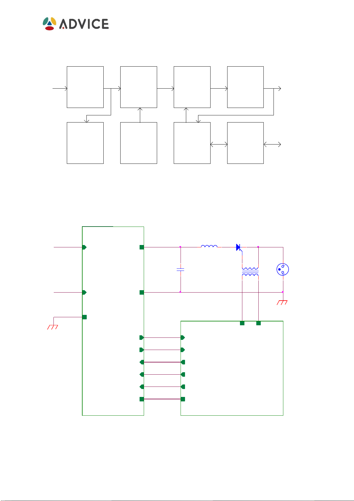
The above diagram depicts a typical laser-based system with a controller connected
to the capacitor charger, which in turn drives a flash lamp through a pulse forming
network (PFN) comprised by a high voltage capacitor discharging through an
inductor into the flash lamp for achieving a high intensity flash.
There are additional applications but this section describes only the main application
of driving a flash lamp in order to achieve a laser shot.
In case there is any doubt about any application, please apply to your local Advice
Electronics Ltd. Representative, and they will be glad to assist.
The capacitor charger charges the high voltage capacitor, then the controller turns
on the SCR by inducing a short pulse through the transformer which offers also
insulation from the high voltage. Once the high voltage capacitor transferred its
energy to the flash lamp and the flash has been achieved, the current decreases and
the SCR turns OFF and the high voltage capacitor may be charged again for the
next flash.
It is highly recommended to connect a high voltage reverse protective diode in
parallel to the high voltage capacitor (with is anode connected to the –OUT and its
cathode to the +OUT).
In order to drive a flash lamp for achieving a laser shot, the controller will typically
perform the following sequence:
a. The controller sets the desired voltage by accordingly applying a voltage in
the "VOLTAGE PROGRAM" pin of the interface connector (pin 5).
b. The controller checks the capacitor charger status through signal "SUM
FAULT", making sure it is in "high" state, indicating the capacitor charger has
no faults and is ready to operate.
c. The controller activates the "INHIBIT" signal, which initiates the high voltage
capacitor charging process.
d. The controller waits until an active signal "END OF CHARGE" is received,
indicating the capacitor charger has charged the high voltage capacitor to the
desired voltage. It may check the "VO MOITOR INSTANTANEOUS" analog
signal as a means of double-check.
e. The controller de-activates the "INHIBIT" command signal, inducing the
capacitor charger into an idle state.
Note: In this kind of application the user must take care to de-activate the
"INHIBIT" command signal prior to discharging the load capacitor.
Otherwise the capacitor charging power supply will keep on delivering
energy during the discharge and may be disturbed by the capacitor high