Schweißkraft CRAFT-TIG 201 DC P PULSE User manual

CRAFT-TIG 201 DC P PULSE
Operating Instructions
CRAFT-TIG 253 DC PULSE
TIG-INVERTER
TIG-Inverter
CRAFT-TIG 201 DC P PULSE

CRAFT-TIG-Series | Version 1.06
Imprint
Product identification WIG-Inverter Item number
CRAFT-TIG 201 DC P PULSE 1074201
CRAFT-TIG 253 DC PULSE 1074202
Manufacturer Stürmer Maschinen GmbH
Dr.-Robert-Pfleger-Str. 26
D-96103 Hallstadt
Fax: 0951 96555-55
E-Mail: info@schweißkraft.de
Internet: www.schweißkraft.de
Indications regarding the operating instruc-
tions
Original instructions
Edition: 13.03.2020
Version: 1.06
Language: English
Author: SN/ES
Indications regarding the copyright Copyright © 2020 Stürmer Maschinen GmbH, Hallstadt, Germany.
The contents of these operating instructions is the sole property of the com-
pany Stürmer Maschinen GmbH.
Passing on as well as copying of this document, the use and distribution of its
content are prohibited if not explicitly permitted. Contraventions are liable to
compensation.
Subject to technical modifications and error.

CRAFT-TIG-Series | Version 1.06 3
Contents
1 Introduction.............................................................................................. 4
1.1 Copyright .............................................................................................4
1.2 Customer service.................................................................................4
1.3 Limitation of liability..............................................................................5
2 Safety........................................................................................................ 5
2.1 Symbol explanation .............................................................................5
2.2 Qualification of the staff .......................................................................6
2.3 Personal protective equipment............................................................6
2.4 General safety instructions ..................................................................7
2.5 Safety markings on the welding machine............................................7
3 Intended Use............................................................................................ 8
4 Principle of operation.............................................................................. 9
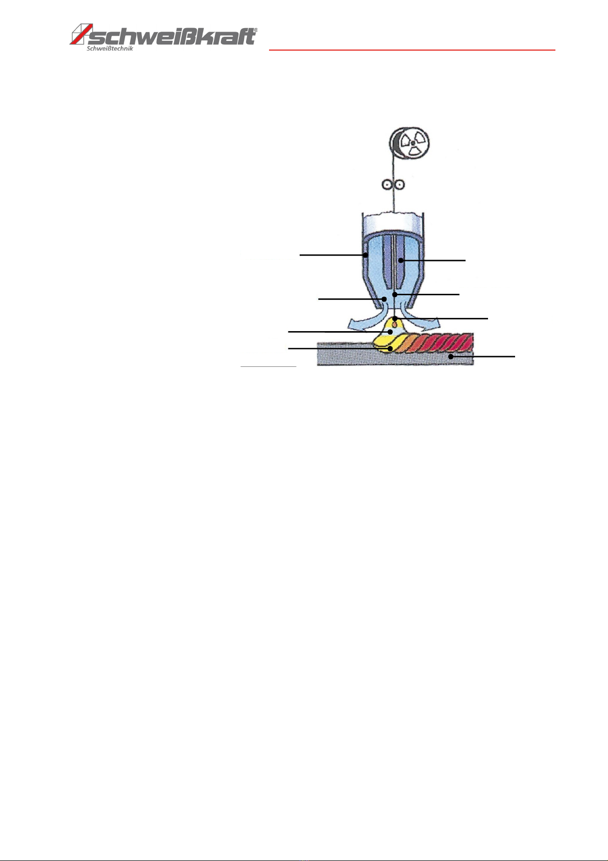
4.1 Principle of tungsten inert gas welding ...............................................9
4.2 Principle of manual arc welding (MMA)...............................................10
5 Technical Data.....................................................................10
5.1 Table....................................................................................................10
5.2 Type plate............................................................................................12
6 Transport, packaging, storage...........................................12
6.1 Transport..............................................................................................12
6.2 Packaging............................................................................................12
6.3 Storage ................................................................................................12
6.4 Installation conditions ..........................................................................12
7 Scope of delivery.................................................................13
8 TIG-Inverter characteristics...............................................13
8.1 Function principle ................................................................................14
8.2 Volt-Ampere Characteristic..................................................................15
8.3 Duty cycle and thermal protection.......................................................16
8.4 Assembly of equipment (TIG/WIG)......................................................16
8.5 Polarity connection (MMA)...................................................................18
9
Description of the operating and connection elements
.......19
10 Welding..............................................................................27
10.1 Welding methods...............................................................................31
10.2 Welding current .................................................................................31
10.3 2-T operation......................................................................................31
10.4 4-T operation......................................................................................31
10.5 Pulse function ....................................................................................32
10.6 Starting with welding..........................................................................32
10.7 TIG welding........................................................................................33
10.8 Welding with rod electrode (MMA)....................................................34
10.9 TIG welding........................................................................................35
10.10 Argon ARC welding application ......................................................35
11 MMA welding.....................................................................38
12 Electrical connection........................................................39
13 Welding instructions.........................................................39
13.1 Notes to the welding technology .......................................................40
14 Care and maintenance......................................................42
15 Troubleshooting................................................................44
16 Disposal, Recycling of old equipment.............................50
16.1 Decommission ...................................................................................50
16.2 Disposal of electrical equipment .......................................................50
16.3 Disposal via municipal collection points............................................51
17 Spare parts........................................................................51
17.1 Spare parts order...............................................................................51
17.2 Spare parts drawings ........................................................................52
18 Wiring diagram..................................................................54
19 Electrical circuit diagrams................................................56
19.1 Electrical circuit diagram CRAFT-TIG 201 DC P PULSE ...................56
19.2 Electrical circuit diagram CRAFT-TIG 253 DC PULSE ......................57
20 EC Declaration of Conformity..........................................58
21 Notes..................................................................................59

4CRAFT-TIG-Series | Version 1.06
Introduction
1 Introduction
With the purchase of the welding machine made by Schweißkraft you have
made a good choice.
Read the operating instructions carefully before commissioning.
This informs about the proper commissioning, the intended use as well as the
safe and efficient operation and maintenance of the device.
The operating instructions are part of the device. It must always be stored at the
place of use of the device. In addition, the local accident prevention regulations
and general safety regulations apply to the area of application of the device.
Illustrations in this operating manual serve the general understanding and
may deviate from the actual design.
1.1 Copyright
The contents of this manual are protected by copyright. Their use is permitted
within the scope of use of the device. Any further use is not permitted without
the written permission of the manufacturer. We hereby apply for trademark,
patent and design rights to protect our products, if this is possible in indivi-
dual cases. We vigorously oppose any infringement of our intellectual pro-
perty.
1.2 Customer service
If you have any questions about your SYN-MAG Series or technical informa-
tion, please contact your dealer. There you will be happy to help with expert
advice and information.
Germany:
Stürmer Maschinen GmbH
Dr.-Robert-Pfleger-Str. 26
D-96103 Hallstadt
Repair-Service:
Fax: 0049 (0) 951 96555-111
Email: service@stuermer-maschinen.de
Spare parts orders:
Fax: 0049 (0) 951 96555-119
Email: ersatzteile@stuermer-maschinen.de
We are always interested in information and experiences that arise from the
application and can be valuable for the improvement of our products.

Safety
CRAFT-TIG-Series | Version 1.06 5
1.3 Limitation of liability
All information and instructions in the operating instructions have been compi-
led taking into account the applicable standards and regulations, the state of
the art as well as our many years of knowledge and experience. In the follo-
wing cases, the manufacturer assumes no liability for damages:
- Failure to observe the operating instructions,
- Improper use,
- Use of untrained personnel,
- Unauthorized conversions,
- Technical changes,
- Use of unauthorized spare parts.
The actual scope of delivery may differ from the explanations and illustrations
described here for special versions, when using additional order options or
due to the latest technical changes.
The obligations agreed in the delivery contract, the general terms and condi-
tions as well as the delivery conditions of the manufacturer and the legal regu-
lations valid at the time of the conclusion of the contract apply.
2 Safety
This section provides an overview of all major safety packages for personal
protection and safe and trouble-free operation. Further task-related safety in-
structions are contained in the individual chapters.
2.1 Symbol explanation
Safety instructions Safety instructions are indicated by symbols in these operating instructions.
The safety instructions are initiated by signal words that express the extent of
the hazard.
DANGER!
This combination of symbol and signal word indicates an
immediately dangerous situation. It leads to death or serious
injury if it is not avoided.
WARNING!
This combination of symbol and signal word indicates a potenti-
ally dangerous situation. It leads to death or serious injury if it is
not avoided.
CAUTION!
This combination of symbol and signal word indicates a
potentially dangerous situation. It can cause minor or minor
injuries if not avoided.
NOTE!
This combination of symbol and signal word indicates a po-
tentially dangerous situation. It can lead to material and env-
ironmental damage if it is not avoided.

6CRAFT-TIG-Series | Version 1.06
Safety
Tips and recommendations
To reduce the risk of personal injury and property damage and to avoid dan-
gerous situations, the safety instructions in this manual must be observed.
2.2 Qualification of the staff
The various tasks described in this manual place different demands on the
qualifications of the people entrusted with these tasks.
Only persons who can be expected to carry out this work reliably are permit-
ted to carry out all work. Persons whose reactivity is influenced, e.g. by drugs,
alcohol or medication, are not permitted.
Operator The operator has been instructed in a briefing by the operator about the tasks
assigned to him and possible dangers of improper behavior. The operator
may only carry out tasks that go beyond normal operation if this is specified in
this operating manual and the operator has expressly entrusted this to him.
Specialist staff Due to their professional training, knowledge and experi-ence as well as their
knowledge of relevant regulations the specialist staff is able to perform the as-
signed tasks and to recognise and avoid any possible dangers them-selves.
2.3 Personal protective equipment
The personal protective equipment serves to protect per-sons against impair-
ments of safety and health while working. The staff has to wear personal protec-
tive equip-ment while performing different works on and with the welding equip-
ment which are indicated in the individual paragraphs of these instructions.
The personal protective equipment is explained in the following paragraph:
Tips and recommendations
This symbol indicates useful tips and recommendations as
well as information for efficient and trouble-free operation.
WARNING!
Danger due to insufficient qualification of persons!
Insufficiently qualified persons can not assess the risks
involved in handling the machine and expose themselves
and others to the risk of serious or fatal injuries.
- All work should only be carried out by qualified persons.
- Keep inadequately qualified persons out of the work area.
Welders face protection shield or helmet with welder's face
protection shield
Wear a welding helmet fitted with a proper shade of filler to
protect your face and eyes when welding or watching (see
Safety Standards).
Protective gloves with pulse protection
The protective gloves with pulse protection protect hands
from sharp-edged components as well as from friction,
abrasions, minor burns or deeper injuries.
Protective apron
The protective apron mainly protects the front of the body
against sparks or radiation during welding.

Safety
CRAFT-TIG-Series | Version 1.06 7
2.4 General safety instructions
The following must be observed: - The device must not be modified in its design and must not be used for
purposes other than those provided for by the manufacturer.
- Never work under the influence of concentration-disturbing diseases, fati-
gue, drugs, alcohol or medication.
- Keep children and persons not familiar with the TIG inverters away from
their working environment.
2.5 Safety markings on the welding machine
Safety signs and instructions are attached to the device (Fig. 1) which must
be observed and followed.
Fig. 1: 1 Mandatory sign I 2 Warning sign
The safety labels and instructions attached to the device must not be remo-
ved. Damaged or missing safety markings can lead to malfunctions, personal
injury and property damage. They are to be replaced immediately.
If the safety markings and instructions are not immediately recognizable and
comprehensible, the device must be taken out of operation until new safety
markings have been affixed.
Safety boots
The safety boots protect the feet against crushes, falling
parts and slipping over on slippery under-ground.
Protective clothes
The protective clothes are tight clothes of little tensile
strength.
WARNING!
Danger in case of misuse!
The device may only be operated in a technically perfect condition. Any
faults must be rectified immediately. Unauthorized modifications to the
TIG inverters or improper use of the TIG inverters as well as disregard of
the safety regulations or the operating instructions exclude the manu-
facturer's liability for any resulting damage to persons or objects and
invalidate the warranty claim!
123
12

8CRAFT-TIG-Series | Version 1.06
Intended Use
3 Intended Use
The device is exclusively designed for arc welding according to MMA and
TIG. Intended use also includes compliance with all information in these in-
structions. No other use is permitted. Any use beyond the intended use or any
other use is considered misuse.
Stürmer Maschinen GmbH does not assume any liability for constructive and
technical changes to the device. Claims of any kind due to damage due to im-
proper use are excluded.The TIG inverters welding devices are direct current
inverters with high-frequency ignition and pulse function. The required wel-
ding current can be infinitely adjusted via a rotary control. The HF ignition
enables contactless ignition of the arc. Exceeding the permissible tempera-
ture of the power components is indicated by a display on the control panel.
The housing ensures the protection of the components against external influ-
ences and against direct contact. Depending on the application, there are
different degrees of protection against penetration of solid bodies and water.
The degree of protection (Fig. 2) is indicated by the letters IP, followed by two
digits: the first digit indicates the degree of protection against solid bodies
and the second the degree of protection against water.
Fig. 2: Degre of protection IP21
WARNING!
Danger in case of misuse!
Misuse of the device can lead to dangerous situations.
- Only operate the device in the power range specified in
the technical data.
- Never bypass or disable the safety devices.
- Only operate the device in a technically perfect condition.
- Keep away from all moving parts.
NOTE!
The Schweißkraft welding equipment may only be operated
by persons who have been instructed in the use of welding
equipment and are familiar with safety regulations.
- Always wear protective clothing when welding to protect
against splashes and sparks.
- Make sure that other persons are not endangered by the
UV radiation of the arc.
Protected
against verti-
cally falling
dripping water
Protect against
solid objects over
12 mm e.g.
hands, large tools
S
2
Tested
when mo-
ving parts
are at a
standstill
1
IP21

Principle of operation
CRAFT-TIG-Series | Version 1.06 9
4 Principle of operation
4.1 Principle of tungsten inert gas welding
Fig. 3: Metal inert gas welding
In TIG welding (Wolfram Inert* Gas Welding ) an arc is drawn between a non-
meltable tungsten electrode. Pure argon is usually used as the shielding gas -
a noble gas that does not combine with any element and therefore also pre-
vents reactions of the molten metal. The filler wire is supplied without current,
either manually (manual welding) or mechanically (automatic welding). Howe-
ver, there are welding operations that do not require filler materials. It de-
pends on the material used whether direct or alternating current is used. The
main advantage of TIG welding is the wide range of materials to be welded.
Materials from 0.3 mm thickness (automated) such as alloyed steels, high-al-
loy steels, aluminium (alternating current welding), magnesium, copper and
their alloys, unalloyed steels, nickel, gold, silver, titanium and many more can
be welded. Can be used for welding all material thicknesses and root layers
with thicker cross-sections. The TIG process achieves the best results com-
pared to other welding processes due to pore-free welds with a very high ten-
sile strength.
Alternating current welding (AC): For welding of aluminium. A hemispherical tungsten dome forms on the
tungsten electrode and the arc changes in high frequency between the minus
and plus poles.
Direct current welding (NC): For welding alloyed steels and non-ferrous metals. The tungsten electrode is
ground to a point. The arc burns stable.
HF ignition = contactless ignition
Lift-Arc ignition = contact ignition
Welding wire coil
Welding wire rollers
Current contact nozzle
Wire electrode
Drop transfer
Workpiece
Shield cup
Inert gas
Electric arc
Melting bath

10 CRAFT-TIG-Series | Version 1.06
Technical Data
4.2 Principle of manual arc welding (MMA)
Electrode welding is an uncomplicated welding method with which almost all
metals can be welded. This method can also be used outdoors and with spe-
cial equipment even under water. In electrode welding, the arc length is de-
termined by hand. The distance between the electrodes determines the arc
length. Welding is mainly carried out under direct current; e.g. rutile electro-
des are easy to weld under minus-pole direct current; basic electrodes under
plus-pole direct current. The electrode is an arc carrier and additional mate-
rial. It consists of a core wire and a cladding. The cladding protects the mol-
ten pool from harmful atmospheric oxygen and stabilizes the arc. In addition,
a slag forms which protects and shapes the weld seam. Depending on the
thickness and composition of the coating, a distinction is made between rutile
and basic electrodes. Rutile electrodes are easier to weld and have a beauti-
ful flat seam. The slag is also easier to remove. It should be noted that many
electrodes have to be redried after prolonged storage because moisture ac-
cumulates from the air over time. Otherwise, electrode welding is a very com-
mon and easy-to-use welding process.
5 Technical Data
5.1 Table
Rod electrode
Slag and gas
Melted
zone
Coating
Core rod
Arc
Base
material
Parameter CRAFT-TIG 201
DC P PULSE
CRAFT-TIG 253
DC PULSE
Length (Product) [mm] 500x150x280 480x190x350
Net weight [kg] 9,7 15,1
Norm /
EMV-Class
IEC 60974-1:2012 / A
Connecting cable length [m] 2,2 2,2
Supply voltage [V] 90~275 400±10%
Type of current / Phase (s) [Ph] AC / 1 AC / 3
Mains frequency [Hz] 50/60 50/60
P o w e r i n p u t [ A ] 1 1 0 V : T I G 2 3 . 9
1 1 0 V : M M A 3 8 . 6
2 3 0 V : T I G 1 9 . 7
230V: MMA 30.1
MMA 18.6/
TIG 13.5

Technical Data
CRAFT-TIG-Series | Version 1.06 11
5.2 Type plate
Fig. 4: Type plate CRAFT-TIG 201 DC P PULSE
Power draw [kVA] 110V: TIG 2.6
1 1 0 V : M M A 4 . 2
230V: TIG 4.5
230V: MMA 6.9
10.6 /
7.7
Degree of protection IP21S IP21S
Isolation class H H
Fuse slow-blow [A] 16 16
Required generator power >6.9 kVA >10,6 kVA
Mains plug [A] 16 no
Open circuit voltage [V] 110V: TIG 66.5
110V:MMA66.7
2 3 0 V : T I G 6 6 . 5
230V: MMA 66.7
MMA 70.5/
TIG 60.5
Operating temperature [C°] -10~40 −10~40
Weldable electrode Ø [mm] 1.6~4.0 1.6~5.0
Adjustment range TIG DC [A] 5~200 5~250
Adjustment range electrode [A] 5~200 5~250
Duty cycle at Imax. 40°C TIG DC [%] 50 60
Duty cycle at Imax. 40°C electrode [%] 30 60
Current at ED 100% 40°C
WIG [%]
145 195
Current at ED 100% 40°C electrode [%]
135 195
Power consumption
TIG DC [kVA]
4,5 5
Power consumption
electrode [kVA]
6,9 7.1
Pulse frequency [Hz] 0.5~200 0.5~200
Ignition high frequency
Torch cooling Air Air
Performance factor [cos phi] 0,99 0,67
Sheet thicknesses [mm] 0.5+10.0 0.5+12.0
Parameter CRAFT-TIG 201
DC P PULSE
CRAFT-TIG 253
DC PULSE

12 CRAFT-TIG-Series | Version 1.06
Transport, packaging, storage
6 Transport, packaging, storage
6.1 Transport
Check the delivery After delivery, check the device for visible transport damage. If you discover
any damage to the device, report it immediately to the transport company or
dealer.
6.2 Packaging
All used packaging materials and packaging aids are recyclable and should
be taken to a materials recycling depot to be disposed of.
The delivery packaging is made of cardboard, so please dispose carefully by
having it chopped up and given to the recycling collection.
The film is made of polyethylene (PE) and the cushioned parts of polystyrene
(PS). Deliver these substances to a collection point for recyclable materials or
to the waste disposal company which looks after your region.
6.3 Storage
The welding machine must be installed in closed, dry and well-ventilated
rooms with room temperatures between 15 and 35 degrees. It must not be ex-
posed to moisture or intense sunshine.
6.4 Installation conditions
The device has been designed for use in roofed rooms and must be set up in
a dry environment:
- Operating range above sea level: below 1000 metres.
- Application temperature range: -10°C to +40°C.
- Relative humidity in the environment must be below 90% (20°C).
- Place the unit at a certain angle to the floor. The angle must not
exceed 15°.
- Protect the device from the influence of rain or direct sunlight in hot con-
ditions.
- The content of dust, acid, harmful gases in the ambient air or sub-
stances must not exceed the normal standard.
- The ambient air must be free of dust, acids, salts or concentrations of
iron or metal powders.
- Ensure that there is sufficient ventilation during welding.
- There must be at least 30 cm between the device and the wall.
Ensure that there is sufficient space in front of the device so that the operating
elements can be easily reached and viewed. Position the unit so that the air
inlet and outlet are not obstructed. Make sure that no metal parts, dust or
other foreign objects can penetrate into the device.
Moving and positioning When moving, handle the welding device carefully and do not tip it over.
Please use the handle on the top of the welder to move the unit.
Make sure that the welder is well positioned after it has been placed in the fi-
nal working position. When the welder is used, it is necessary to fix it in place
to prevent it from slipping.
When using a forklift truck, its arm length must be long and wide enough to
pick up and lift the welder according to its center of gravity.
DANGER! ELEKTRICAL CONNECTION
Do not use the device outdoors in the rain!
Ambient conditions must be adequate for IP21
protection!

Scope of delivery
CRAFT-TIG-Series | Version 1.06 13
The welding movements can lead to a possible danger or material hazard.
Therefore, make sure that the machine is in a safe position before using it.
7 Scope of delivery
CRAFT-TIG 201 DC P PULSE - Gas hose 4 m incl. quick connector
- Burner TIG 26 4 m
- Pressure reducer
- 3 m ground cable 16 mm² with ground terminal
- 3 m welding cable 16 mm² with electrode holder
- Operating Instructions
CRAFT-TIG 253 DC PULSE - TIG-Inverter
- Earth cable CAA 25 mm2SQ 3m with ground clamp
- Gas hose 4 m incl. quick connector
- Hose clamp
- Operating instructions
8 TIG-Inverter characteristics
Current-carrying conductors generate electromagnetic fields (EMF). So far,
no negative effect of these magnetic fields on health has been proven. Never-
theless, a hazard cannot be completely excluded.
The TIG-Inverters are TIG welding machines with pulse width modulation and
IGBT circuit. These inverter power sources are characterized by low weight
and excellent welding properties. Furthermore the power consumption is re-
duced considerably.
All required parameters can be set on the operating display (gas pre-curr-
ents, start current, current rise, current reduction time, final current, gas post-
currents, as well as the pulse parameters).
The TIG DC, TIG DC P-series welding machines are suitable for welding in all
positions for different sheets of stainless steel, carbon steel, alloy steel, tita-
nium, magnesium, copper, etc. It is also used for welding work on pipes, re-
pairing places, in the petrochemical industry, architectural decoration, car re-
pair, bicycle industry, in crafts and general manufacturing.
Characteristics: MMA - Manual metal ARC welding
PWM - Pulse width modulation
IGBT - Bipolar transistor with isolated gate electrode
TIG - Wolfram inert gas welding
TIG DC and TIG DC P Characteristics: - DC TIG and E-Hand (MMA), IGBT technology and pulse width modula-
tion (PWM).
- High performance MCU, Digital control, Digital display.
- Preset all parameters with hold process.
NOTE!
For your own safety you should observe the following to
minimize the electromagnetic field lines:
- Lay the cables as far away from your body as possible.
- Never wrap welding cables around your body.
- Connect the earth cable as close as possible to the wel-
ding point.
- Special care must be taken with pacemakers!

14 CRAFT-TIG-Series | Version 1.06
TIG-Inverter characteristics
- HF/Lift TIG, current down slope and up slope, gas post-flow, Pulse Fre-
quency.
- Intelligent protection: over-voltage, under-voltage, over-current, over-heat.
1. E-Hand (MMA): polarity connection can be chosen according to different
electrodes.
2. For DC TIG, DCEP is used normally (workpiece connected to positive pola-
rity, while torch connected to negative polarity). This connection has many
characters, such as stable welding arc, low tungsten pole loss, more wel-
ding current, narrow and deep weld.
3. DC Pulsed TIG has the following characters:
1) Pulse heating. Metal in Molten pool has short time on high temperature sta-
tus and freezes quickly, which can reduce the possibility to produce hot
crack of the materials with thermal sensitivity.
2) The workpiece gets little heat. Arc energy is focused. Be suitable for thin
sheet and super thin sheet welding.
3) Exactly control heat input and the size of the molten pool. The depth of pe-
netration is even. Be suitable for welding by one side and forming by two si-
des and all position welding for pipe.
4) High frequency arc can make metal for microlite fabric, eliminate blowhole
and improve the mechanical performance of the joint.
5) High frequency ARC is suitable for high welding speed to improve the pro-
ductivity.
8.1 Function principle
The function principle of the
CRAFT-TIG 201 DC P PULSE
is shown as the fol-
lowing figur
(Fig. 5).
Single phases work frequency AC
110V/220V (50 Hz) AC
is rectified into DC
(155/312 V)
, then is converted to medium frequency AC by
inverter device
(IGBT), after reducing voltage by medium transformer (the
main transformer) and rectifying by medium frequency rectifier (fast recovery
diode), and is outputted by inductance filtering. The output is made by in-
ductance filtering. The circuit is controlled by a controller to keep the output
voltage stable. The parameters of the welding current can be adjusted contin-
uously and steplessly to satisfy the requirements of the welding task.
Fig. 5: Function principle of CRAFT-TIG 201 DC P PULSE
The function principle of the
CRAFT-TIG 253 DC PULSE
is shown as the fol-
lowing figur
(Fig. 6). Three-phase 380V line frequency AC is rectified into DC
(about 530V), then is converted to medium frequency AC (about 20KHz) by
inverter device (IGBT), after reducing voltage by medium transformer (the
main transformer) and rectified by medium frequency rectifier (fast recovery
diode), and is outputted by inductance filtering. The circuit adopts current
feedback control technology to insure current output stability. Meanwhile, the
welding current parameters can be adjusted continuously and steplessly to
meet with the requirements of welding craft.

TIG-Inverter characteristics
CRAFT-TIG-Series | Version 1.06 15
Fig. 6: Function principle of CRAFT-TIG 253 DC PULSE
8.2 Volt-Ampere Characteristic
The TIG-Inverters CRAFT-TIG 201 DC P PULSE, CRAFT-TIG 253 DC PULSE
have an optimized volt-ampere characteristic (see diagram). In TIG mode, the
ratio between nominal voltage U2and welding current I2is as follows:
IF I2≤600 A, U2= 10 + 0,04 I2(V); IF I2 > 600A, U2 = 34 (V)
Fig. 7: Volt-Ampere Characteristic
8.3 Duty cycle and thermal protection
The “X”-axis stands for Duty Cycle, which is defined as the portion of the time
a welding machine can weld continuously with it’s rated output current within
a certain time cycle (10 minutes).

16 CRAFT-TIG-Series | Version 1.06
TIG-Inverter characteristics
Fig. 8: Example 160 A/ 2.5 minutes welding time
If the welding device is overheated, the thermoswitch responds and puts the
welding device out of operation. Display: red LED overheating. If the thermal
protection is activated, the device should remain switched on for approx. 15
minutes in order to be cooled down by the fan.
8.4 Assembly of equipment (TIG/WIG)
DC POSITIVE CONNECTION The workpiece is connected to the positive electrode of the welding machine
and the welding torch is connected to the negative electrode. In general, the
DC POSITIVE CONNECTION is operated in TIG welding mode.
DC NEGATIVE CONNECTION The workpiece is connected to the negative electrode of the welding machine
and the welding torch is connected to the positive electrode.
Equipment Components:
- Welding torch control cable consisting of two wires.
- Pedal control consisting of 3 wires.
- Flight socket (has 14 cables for the CRAFT-TIG 201 DC P PULSE and 12
cables for the CRAFT-TIG 253 DC PULSE).
- Wear parts for the TIG welding torch, e.g. tungsten electrode, tip, gas
nozzle, electrode shield (short/long).
When using welding equipment with the HF ignition method, the ignition spark
may cause interference in the equipment near the welding equipment. Make
sure that special safety precautions or shielding measures are taken.

TIG-Inverter characteristics
CRAFT-TIG-Series | Version 1.06 17
Fig. 9: Connection of the equipment CRAFT-TIG 253 DC PULSE
Fig. 10: Connection of the equipment CRAFT-TIG 201 DC P PULSE
Pressure controller
Gas cylinder
Gas input
Control cable
Workpiece
TIG gun
Gas connector
Control cable of
torch switch

18 CRAFT-TIG-Series | Version 1.06
TIG-Inverter characteristics
8.5 Polarity connection (MMA)
MMA (DC): Select the connection type DCEN or DCEP according to the
electrode to be used. Refer to the Electrode instructions for infor-
mation.
The provided cables are for the connection of the welding material with the
device. The welding material must be clean at the connection with the ground
clamp to achieve good contact. The ground clamp must always be
connected directly to the workpiece and to ¨+¨ or ¨-¨ Connection on the device
side - according to the instructions of the electrode manufacturer.
Fig. 11: Polarity connection
CRAFT-TIG 253 DC PULSE: CRAFT-TIG 201 DC P PULSE
Fig. 12: Direct current connection options CRAFT-TIG 253 DC PULSE (left), CRAFT-TIG 201 DC P PULSE (right)
CRAFT-TIG 201 DC P PULSE and CRAFT-
TIG 253 DC PULSE:
Two sockets are available for connecting the output cables to this welding
machine. In E-Hand welding, the electrode holder is connected to the positive
socket, while the ground wire (workpiece) is connected to the negative soc-
ket, called DCEP.
Depending on the electrode, however, a different polarity is required for opti-
mum results and therefore polarity should be taken into account. Information
on correct polarity can be found in the information provided by the electrode
manufacturers.
DCEP: Electrode is connected to the "+" pole socket.
DCEN: Electrode is connected to the "-" pole socket.
MMA (DC): Selection of the DCEN or DCEP connection according to the diffe-
rent electrodes. Please refer to the electrode manual.
MMA (AC): No polarity connection requirements.

Description of the operating and connection elements
CRAFT-TIG-Series | Version 1.06 19
Step 1: Connect the earth cable to the "-" pole, fastening it clockwise.
Step 2: Connect the ground clamp to the workpiece. The contact with the
workpiece must be a solid contact with clean, bare metal, without cor-
rosion, paint or scale at the contact point.
Step 3: Connect the electrode leads to the "+", turn it clockwise to tighten.
Step 4: Each unit is equipped with a power cord. This should be connected to
the input voltage of the welding power cable at the appropriate posi-
tion. Be sure to select the correct voltage.
Step 5: Ensure good contact with the appropriate input of the power supply
connector or socket to prevent oxidation.
Step 6: Measure with a multimeter whether the input voltage is in the fluctua-
tion range.
Step 7: The power supply ground must be well grounded.
9 Description of the operating and connection elements
CRAFT-TIG 201 DC P PULSE:
1
„+“ Connection: Positive output of the welding machine with reference to
polarity.
2 „-“ Connection: Negative output of the welding machine with reference to
polarity.
3 Socket: Connected to the torch control switch cable (has 14 wires and line
8 - line 9 are connected to the torch switch control cable).
4 Inert gas connection: Is connected to the gas inlet of the welding torch.
Fig. 13: Operating and connection elements 5 Power supply toggle switch: In "ON" position, the welding machine is swit-
ched on. In "OFF" position, the welder is switched off.
6 Power source input: For connecting the power source.
7 Quick connection for the inert gas: For connecting one coupling of the gas
hose. The other end of the gas hose is connected to the argon cylinder.
CRAFT-TIG 253 DC PULSE:
1 „-“ Connection: Negative output of the welding machine with reference to
polarity.
2 Inert gas connection: Is connected to the gas inlet of the welding torch.
3 Socket: Connected to the welding torch control switch cable.
4 „+“ Connection: Positive output of the welding machine with reference to
polarity
Fig. 14: Operating and connection elements
5 Quick connection for the inert gas: For connecting one coupling of the gas
hose. The other end of the gas hose is connected to the argon cylinder.
6 Water tank connection: Connected to the water tank.

20 CRAFT-TIG-Series | Version 1.06
Description of the operating and connection elements
7 Power source input: For connecting the power source.
8 Quick connection for the inert gas: For connecting one coupling of the gas
hose. The other end of the gas hose is connected to the argon cylinder.
Water cooler:
32 Water inlet.
33 Water return connection (red).
34 Water supply connection (blue).
35 Power supply switch.
36 Connection for controlling the water cooler.
Fig. 15: Operating and connection elements
Control panels Overview:
Main features of the control panel are the logical way in which the control is
arranged. All the main parameters needed in daily use can be easily set:
- can be selected using the keys.
- changed with the setting dial.
- shown on the display during welding.
The figure below shows an overview of the main settings required for daily use.
In the following section you will find a detailed description of these settings.
CRAFT-TIG 201 DC P PULSE:
Fig. 16: Control panel CRAFT-TIG 201 DC P PULSE
Function select button
2T /4T select button
Multifunction display
Warning light
Parameter selection
and input button
TIG parameter setting
(welding current and
other parameters)
MMA
parameter
setting
This manual suits for next models
1
Table of contents
Other Schweißkraft Welding System manuals
Popular Welding System manuals by other brands

Cebora
Cebora POWER SPOT 5600 Service manual

Migatronic
Migatronic MIGALOG quick guide

Elektra Beckum
Elektra Beckum mig mag 232 ep operating instructions

Parkside
Parkside PPSK 40 A1 Operation and safety notes

Astro Pneumatic Tool
Astro Pneumatic Tool COMBI120 quick start guide

Milweld
Milweld H-10 owner's manual

Miller
Miller SQUAREWAVE 1000 owner's manual

Kemppi
Kemppi Kempomat 2500 operating manual

Migatronic
Migatronic AUTOMIG 223i/273i instruction manual

Lincoln Electric
Lincoln Electric OUTBACK 185 IM972 Operator's manual

Miller
Miller DIMENSION NT 450 WCC owner's manual

Kemppi
Kemppi Evo 150, 150VRD operating manual