Schweißkraft EASY-MAG 171 User manual

Operating Instructions
EASY-MAG 171
EASY-MAG
MIG-MAG Shield Gas Welding
Equipment
EASY-MAG 193
EASY-MAG 213
EASY-MAG 171
EASY-MAG 193

2EASY-MAG-Series | Version 2.01
Imprint
Product Identification
MIG MAG Welding Equipment Item number
EASY-MAG 171 1081171
EASY-MAG 193 1081193
EASY-MAG 213 1081213
Manufacturer
Stürmer Maschinen GmbH
Dr.-Robert-Pfleger-Str. 26
D-96103 Hallstadt
Fax: 0049 (0) 951 - 96555-55
Email: info@schweißkraft.de
Internet: www.schweißkraft.de
Indications regarding the operating instructions
Original instructions
Edition: 11.02.2019
Version: 2.01
Language: English
Author: MS/KP
Indications regarding the copyright
Copyright © 2018 Stürmer Maschinen GmbH, Hallstadt,
Germany.
The contents of these operating instructions is the sole
property of the company Stürmer Maschinen GmbH.
Passing on as well as copying of this document, the use
and distribution of its content are prohibited if not expli-
citly permitted. Contraventions are liable to compensa-
tion.
Subject to technical modifications and error.
Content
Imprint .....................................................................2
1 Introduction .............................................................3
1.1 Copyright ............................................................ 3
1.2 Costumer service................................................ 3
1.3 Limitation of liability............................................. 3
2 Safety........................................................................3
2.1 Symbol explanation ............................................ 3
2.2 Obligations of the operation company ................ 4
2.3 Qualification of personnel ................................... 5
2.4 Personal protective equipment ........................... 5
2.5 General safety instructions ................................. 6
2.6 Safety information............................................... 7
2.7 Safety equipment................................................ 7
3 Intended use ............................................................7
3.1 Misuse ................................................................ 8
3.2 Residual risks ..................................................... 8
4 Technical Data.........................................................8
4.1 Table................................................................... 8
4.2 Nameplate .......................................................... 9
5 Transport, Packaging, Storage ..............................9
5.1 Delivery and Transport ....................................... 9
5.2 Packaging ........................................................... 9
5.3 Storage ............................................................... 9
6 Principle of operation .............................................9
6.1 Principle of the metal inert gas welding process. 9
6.2 Functional principle of wire feeding .................. 10
6.3 Components ..................................................... 10
6.4 Insert the welding wire roller ............................. 11
6.5 Burner equipment ............................................. 11
7 Description of the controls...................................12
7.1 Device View EASY-MAG 171 ........................... 12
7.2 Device View EASY-MAG 193 ........................... 12
7.3 Device View EASY-MAG 213 ........................... 13
7.4 On / Off and 230/400V switch........................... 13
7.5 Item function ..................................................... 13
7.6 Display overload ............................................... 13
7.7 Step switch ....................................................... 13
7.8 Wire feed control............................................... 13
8 Set up .....................................................................13
8.1 Scope of delivery .............................................. 13
8.2 Requirements for the installation site................ 14
8.3 Mains connection.............................................. 14
8.4 Assembly instructions....................................... 15
8.5 Connection of the welding torch ....................... 15
8.6 Connection of the workpiece ............................ 15
9 Operation ...............................................................15
9.1 Installation conditions ....................................... 16
9.2 Mains connection.............................................. 16
9.3 Connections of the welding circuit .................... 16
9.4 Welding parameters.......................................... 17
9.5 Preparation of the weld..................................... 17
9.6 Performing welds.............................................. 18
9.7 Description and use of different arc types ........ 19
9.8 Selection of wire electrode and inert gas.......... 19
10 Maintenance.........................................................20
10.1 Scheduled maintenance ................................. 20
11 Troubleshooting..................................................21
12 Disposal, Recycling of old equipment ..............22
12.1 Decommission ................................................ 22
12.2 Disposal of electrical equipment..................... 22
12.3 Disposal via municipal collection points.......... 22
13 Spare parts...........................................................22
13.1 Ordering spare parts....................................... 22
13.2 Spare parts drawings...................................... 23
14 Electric circuit diagram.......................................26
15 EC Decleration of Conformity ............................29

EASY-MAG-Series | Version 2.01 3
Introduction
1Introduction
You have made a good choice by purchasing the weld-
ing machine made by Schweißkraft.
Thoroughly read the operating instructions before commission-
ing the machine.
It informs you about the proper commissioning, the in-
tended use as well as the safe and efficient operation
and maintenance of the welding equipment.
The operating instructions are part of the welding equip-
ment. Always keep it at the place of use of the welding
equipment. Furthermore, the local accident prevention
regulations and the general safety notes are applicable
for the field of application of the welding equipment.
The illustrations in these operating instructions serve the
general comprehension and may deviate from the actual
type.
1.1 Copyright
The contents of these instructions are copyright. Their
application is admissible in the frame of the welding
equipment utilisation. An application beyond the de-scri-
bed application is not allowed without written ap-proval
of the manufacturer.
For the protection of our products, we shall register tra-
demark, patent and design rights, as this is possible in
individual cases. We strongly oppose any infringement
of our intellectual property.
1.2 Customer service
Please contact your dealer if you have questions on the
welding equipment or if you need technical advice. They
will help you with specialist information and expert ad-
vice.
Germany:
Stürmer Maschinen GmbH
Dr.-Robert-Pfleger-Str. 26
D-96103 Hallstadt
Repair-Service:
Fax: 0049 (0)951 96555-111
Email: service@stuermer-maschinen.de
Spare part oders:
Fax: 0049 (0)951 96555-119
Email: ersatzteile@stuermer-maschinen.de
We are always interested in valuable experience and
knowledge gained from using the application, which then
could be shared and be valuable to develop our products
even further.
1.3 Limitation of liability
All information and notes in these operating instructions
were summarised taking the applicable standards and
rules, the state-of-the-art and our long-term knowledge
and experiences into consideration.
In the following cases the manufacturer is not liable for
damages:
- Non-observance of the operating instructions,
- Inappropriate use
- Use of untrained staff,
- Unauthorised modifications
- Technical changes,
- Use of not allowed spare parts.
The actual scope of delivery may deviate from the expla-
nations and presentations described here in case of spe-
cial models, when using additional ordering options or
due to latest technical modifications.
The obligations agreed in the delivery contract, the gen-
eral terms and conditions as well as the delivery condi-ti-
ons of the manufacturer and the legal regulations at the
time of the conclusion of the contract are applicable.
2 Safety
This paragraph will give you an overview of all important
safety packages for the protection of the people using it
well as for a safe and undisturbed operation. Other task-
based safety notes are included in the individual chap-
ters.
2.1 Symbol explanation
Safety instructions
The safety notes in these operating instructions are high-
lighted by symbols. The safety notes are introduced by
signal words which express the concern of the risk.
DANGER!
This combination of symbol and signal words indi-
cates an imminently dangerous situation which may
lead to death or severe injuries if they are not avoi-
ded.
WARNING!
This combination of symbol and signal word indi-
cates a potentially dangerous situation that can lead
to death or serious injury if not avoided.

4EASY-MAG-Series | Version 2.01
Safety
Tips and recommendations
It is necessary to observe the safety notes quoted in
these operating instructions in order to reduce the risks
for personal injuries and damages to property.
2.2 Obligations of the operating company
The operating company is the person who operates the
machine for business or commercial reasons by herself,
or leaves it to a third party for use or application, and who
bears the legal product responsibility for the protection of
the user, the staff or for third parties.
Obligations of the operator:
If the machine is used for commercial purposes, the op-
erating company must comply with the legal working
safety regulations. Therefore, the safety notes in this op-
erating manual, as well as the safety, accident preven-
tion and environment protection regulations applying for
the area of application of the machine must be met. The
following applies in particular:
- The operating company must be informed about
the applying industrial safety regulations and fur-
ther analyse hazards resulting from the special
working conditions at the place of use machine.
She must implement these in form of operating
manuals for the operation machine.
- During the entire lifetime of machine, the operating
company must verify whether the operating manu-
als prepared by her correspond to the current sta-
tus of the regulations, and must adapt these if nec-
essary.
- The operating company must unambiguously regu-
late and determine the responsibilities for installa-
tion, operation, troubleshooting, maintenance and
cleaning.
- The operating company must ensure that all per-
sons who work with machine, have read and un-
derstood this manual. Furthermore she must in-
struct the staff in regular intervals and inform them
about the hazards.
- The operator must provide the necessary protec-
tive equipment to the staff and order the use of the
necessary protective equipment in a binding way.
Furthermore the operating company is responsible to
keep the Machine always in a technically flawless state.
Thus, the following applies:
- The operator must ensure that the maintenance in-
tervals described in this manual are kept.
- The operator must have all safety devices checked
regularly for their good working order and their in-
tegrity.
CAUTION!
This combination of symbol and signal word indi-
cates a potentially dangerous situation that can result
in minor injury if it is not avoided.
ATTENTION!
This combination of symbol and signal words indi-
cates a possibly dangerous situation which may lead
to property and environmental damages if they are
not avoided.
NOTE!
This combination of symbol and signal words indi-
cates a possibly dangerous situation which may lead
to property and environmental damages if they are
not avoided.
Tips and recommendations
This symbol highlights useful tips and recommenda-
tions as well as information for an efficient and trou-
blefree operation.

EASY-MAG-Series | Version 2.01 5
Safety
2.3 Qualification of personnel
The different tasks described in this manual represent
different requirements to the qualification of the persons
entrusted with these tasks.
Only persons reliable working procedures can be ex-
pected from, are allowed to perform all works. Persons
the responsiveness of which is affected by e. g. drugs,
alcohol or medication, are not allowed to work with the
machine.
The qualifications of the personnel for the different tasks
are mentioned below:
Operator:
The operator is instructed by the operating company
about the assigned tasks and possible risks in case of
improper behaviour. Any tasks which need to be per-for-
med beyond the operation in the standard mode must
only be performed by the operator if it is indicated in
these instructions and if the operating company expres-
sively commissioned the operator.
Electrical specialist:
Due to his professional training, knowledge and experi-
ence as well as his knowledge of respective standards
and regulations the electrical specialist is able to perform
works on the electrical system and to recognise and
avoid any possible dangers himself.
Specialist staff:
Due to their professional training, knowledge and experi-
ence as well as their knowledge of relevant regulations
the specialist staff is able to perform the assigned tasks
and to recognise and avoid any possible dangers them-
selves.
Manufacturer:
Certain works may only be performed by specialist per-
sonnel of the manufacturer. Other personnel is not au-
thorized to perform these works. Please contact our cus-
tomer service for the execution of all arising work.
2.4 Personal protective equipment
The personal protective equipment serves to protect per-
sons against impairments of safety and health while wor-
king. The staff has to wear personal protective equip-
ment while performing different works on and with the
welding equipment which are indicated in the individual
paragraphs of these instructions.
The personal protective equipment is explained in the
following paragraph:
WARNING!
Danger due to insufficient qualification of
persons!
Insufficiently qualified persons cannot estimate the
risks while using machine and expose themselves
and others to the danger of severe injuries.
- Have all works only performed by qualified per-
sons.
- Keep insufficiently qualified persons and children
out of the working area.
Ear protection
Hearing protection protects ears from hearing
damage caused by noise. When working overhead
or in confined spaces, ear protection must be used.
Welder face shield or helmet with welder
face shield
The welder's shield, which is worn on the head and
in front of the face or attached to a suitable protective
helmet, protects eyes and face, equipped with
suitable filters.
Protective gloves with pulse protection
The protective gloves with pulse protection protect
hands from sharp-edged components as well as from
friction, abrasions, minor burns or deeper injuries.
Safety shoes
The safety shoes protect the feet against bruising,
falling parts and slipping on slippery surfaces.
Protective clothing
The protective clothing is tight-fitting clothing with low
tear resistance.
Protective apron
The protective apron mainly protects the front of the
body against sparks or radiation during welding.

6EASY-MAG-Series | Version 2.01
Safety
2.5 General safety instructions
Please note the following:
- Welding Welding machines may only be operated by
persons who have been instructed in the use of welding
equipment and are familiar with safety regulations.
- When welding, always wear protective clothing and
take care that other persons are not endangered by the
UV radiation of the arc.
- Avoid direct contact with the welding circuit; the open
circuit voltage provided by the welder is dangerous un-
der certain circumstances.
- The welding cables, tests and repairs may only be
connected when the welding machine is switched off and
disconnected from the mains.
- Before replacing consumable parts of the torch, the
welder must be switched off and disconnected from the
mains.
- The electrical installation must be carried out in accor-
dance with the relevant regulations and accident pre-
vention regulations.
- The welding machine may only be connected to a po-
wer supply system with a grounded neutral conductor.
- Make sure that the power socket is correctly connected
to the protective earth.
- The welder must not be used in humid or wet conditions
or in rain.
- Do not use cables with worn insulation or loose connec-
tions.
- Clean the materials that contain solvents or other sub-
stances that may give rise to toxic gases.
- If a liquid cooling unit is available, it may only be filled
with the welding machine disconnected and dis-
connected from the mains.
- Do not weld on containers, vessels or piping containing
or containing flammable liquids or gases.
- Never weld to containers that are under pressure.
- Remove all flammable substances (eg wood, paper, fa-
bric etc.)
- Provide sufficient air exchange or suitable means to re-
move the fumes released when welding close to the
arc. It is necessary to systematically investigate which
limit values apply to the particular composition, concen-
tration and duration of action of the welding waste ga-
ses.
- The gas cylinder must be protected from heat sources,
including sunlight.
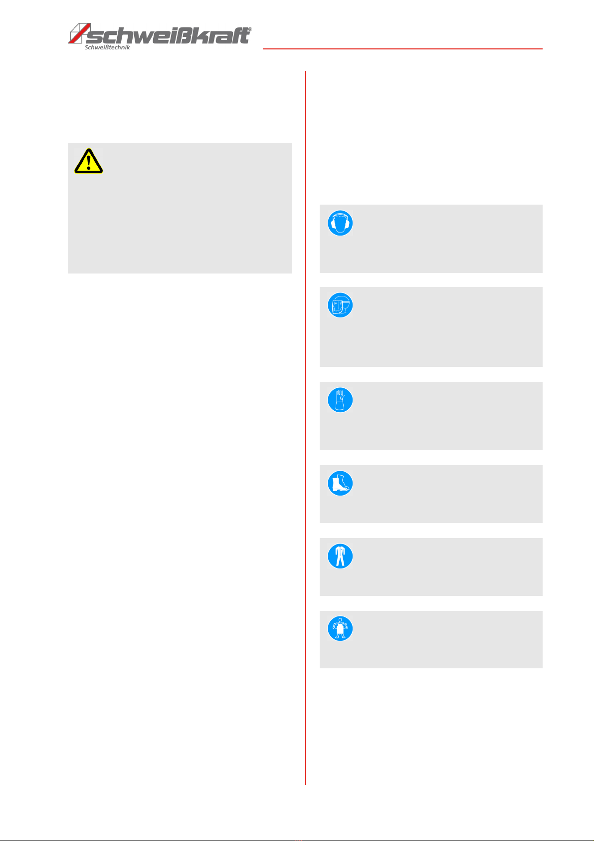
- Provide functional electrical insulation of the electrode,
workpiece, and nearby (accessible) grounded metal
parts. Normally, it is sufficient to wear appropriate gloves,
footwear, headgear and clothing, and to use running
boards and insulating carpets.
- To protect against sparks, heat, visible and invisible ra-
diation, suitable eye protection must be worn (protec-
tive shield or protective cover with standardized radia-
tion glasses of steps 10 to 15 according to DIN 4647,
depending on the welding current).
- Do not wear contact lenses, the strong heat that the
bow gives off, they can merge with the cornea.
- Use functional fire retardant protective clothing and
avoid exposing the skin to UV and infrared radiation
from the arc; Shooters must also use umbrellas or non-
reflective curtains for third parties that are near the arc.
- Noise generation: If a daily level of 85 db (A) or higher
(LEPd) is applied to the person during particularly in-
tensive welding work, functional individual protective
equipment must be used.
- As the welding current transitions, electromagnetic
fields (EMF) are generated near the welding circuit.
The electromagnetic fields may affect medical aids (eg
pacemakers, respiratory aids or metal prostheses).
Appropriate protective measures must be taken for the
providers of such assistance, for example by denying
them access to the operating range of the welding
equipment.
- This welding machine meets the technical product stan-
dards for the exclusive use in the commercial sector
and for professional purposes. Compliance with the ba-
sic limit values that apply to the effects of electroma-
gnetic fields on people in the home environment is not
ensured.
The operator must take the following precautions to re-
duce the impact of electromechanical fields:
- The two welding cables are to be fixed as close to each
other as possible.
- The head and the hull should be kept as far away as
possible from the welding circuit.
- The welding cables must under no circumstances be
wrapped around the body.
- During welding, the body must not be in the middle of
the welding circuit. Hold both cables on the same side
of the body.
- Connect the power return cable to the workpiece as
close to the weld as possible.
- Never close close to the welding machine, sitting on the
welding machine or welding to the welding machine
(minimum distance: 50 cm).
- Do not leave any ferromagnetic objects near the wel-
ding circuit. - Minimum distance d = 25cm.
- Use the guards and secure them securely. Never work
without protections and get them working.
- Always keep the welder and your work environment
clean. Ensure adequate lighting.
- In principle, secure your workpiece when working with
suitable clamping devices. Make sure there is sufficient
contact surface.
- The welder must not be modified in design nor used for
purposes other than those foreseen by the manufactu-
rer.
- Never work under the influence of concentration-distur-
bing illnesses, fatigue, drugs, alcohol or medicines.
- Keep children and persons unfamiliar with the welder
away from their work environment.
- Do not pull on the mains lead to pull the plug out of the
socket. Protect the cable from heat, oil and sharp
edges.
- Protect the welding machine against moisture (danger
of short circuit)
- Before each use of the welding machine, make sure
that no parts are damaged. Damaged parts must be re-
placed immediately to avoid any danger.
- Do not overload the welding machine! You work better
and safer in the specified performance range.
- Only use original spare parts and accessories to avoid
possible dangers and accident risks.

EASY-MAG-Series | Version 2.01 7
Intended use
Additional safety precautions
In welding work
- in environments with increased risk of electric
shock;
- in confined spaces;
- in the presence of flammable or explosive sub-
stances
a "responsible expert" must weigh up the circumstances.
This work may only be carried out in the presence of
other persons who can intervene in an emergency.
- the technical protection means used in 7.10; A.8; A.10
of the standard "EN 60974-9: Arc welding equipment.
Part 9: Building and Operating "are called.
- Welding must be prohibited when the welder or wire
feed system is being worn by the operator (such as
belts).
- Welding must be prohibited when the operator works
above ground level, unless he uses a safety platform.
Voltage between electrode terminals or burners:
When working with multiple welders on a single work-
piece or on multiple, electrically connected workpieces,
the open circuit voltages between two different electrode
terminals or torches can add up to twice the allowable li-
mit.
A specialist coordinator shall carry out an instrument me-
asurement to determine whether there is a risk and
whether the appropriate safeguards are provided for in
point 7.9 of the standard EN 60974-9: Arc welding equip-
ment. Part 9: Building and Operating ".
2.6 Safety information
The welder has safety labels and instructions that must
be observed and followed.
Damaged or missing safety symbols on the welding ma-
chine can lead to malfunctions with personal injury and
property damage. The safety symbols attached to the
welding machine must not be removed. Damaged safety
symbols must be replaced immediately.
From the moment the signs are not immediately recogni-
zable and comprehensible, the welder must be taken out
of service until the new signs are fitted.
2.7 Safety equipment
3 Intended use
This inert gas system is intended exclusively for arc wel-
ding according to MIG (Metal Inert Gas Welding) or MAG
(Metal Active Gas Welding) process. By means of these
two methods, similar metals such as e.g. alloyed or unal-
loyed steels, stainless steels or aluminum welded to-
gether. Another use is not allowed. The welding machine
may only be operated by persons who have been in-
structed in the use of MIG / MAG systems. It may only be
operated in the power range specified in the technical
data.
The device is built and tested according to EN 60974-10
in EMC class A.
Proper use also includes compliance with all information
in this manual. Any use beyond the intended use or
otherwise is considered misuse
For structural and technical changes to the welding ma-
chine, the company Stürmer Maschinen GmbH assumes
no liability.
Claims of any kind due to damage due to improper use
are excluded.
WARNING!
Danger to life due to non-functioning safety
devices!
Failure to operate or disable the safety equipment
can result in serious injury or even death.
- Before starting work, check that all safety equip-
ment is in place and correctly installed.
- Never bypass or override the safety devices.
- Ensure that all safety devices are always acces-
sible.
WARNING!
Danger due to uncontrolled restart!
Uncontrolled restarting of the welding machine can lead
to serious injuries.
- Before switching on again, make sure that the
cause of the shutdown has been eliminated and all
safety devices are mounted and in working order.
- Do not switch on the welding machine until there is
no danger.
WARNING!
This Class A welding equipment is not intended for
use in residential premises where power is supplied
by a public low voltage power supply system. Both
conducted and radiated disturbances may make it
difficult to provide electromagnetic compatibility in
these areas.
WARNING!
Danger in case of misuse!
Misuse of the welder can lead to dangerous situati-
ons.
- Only operate the welding machine in the power
range specified in the technical data.
- Never bypass or override the safety devices.
- Only operate the welding machine in a technically
perfect condition.

8EASY-MAG-Series | Version 2.01
Technical Data
3.1 Misuse
The welder must not be used for thawing (for example
thawing of water pipes) or for heating materials that are
not intended for welding.
3.2 Residual risks
Even if all safety regulations are observed and the wel-
ding machine is used correctly, there are still residual
risks listed below:
- The welder should be set up on a horizontal surface
that can carry the weight; otherwise there is a risk of
tipping (for example, in the case of a ground slope, irre-
gular ground, etc.).
- The bottle should always be secured against overtur-
ning by suitable means.
4 Technical Data
4.1 Table 4.2 Nameplate
The most important information about the operation and
performance of the welding machine are summarized on
the nameplate:
Fig. 1: Type plate of the welding machine EASY-MAG 171
WARNING!
Risk of misuse!
Misuse of the welder can lead to dangerous situati-
ons.
- Only operate the welding machine in the power
range specified in the technical data.
- Never bypass or override the safety devices.
- Only operate the welding machine in a technically
perfect condition.
Parameter EASY-
MAG 171
EASY-
MAG 193
EASY-
MAG 213
Connection voltage
at 50 / 60 Hz (V)
230 400 230/400
Connection cur-
rent, eff.(A)
11 2,3 8,6
Connection cur-
rent, max.(A)
24 9 20,9
Fuses (A) 16 16 16
Adjustment(A) 30 - 170 30 -190 30-140
140-200
Open circuit voltage
(V)
18 - 43 18 - 33 24 - 51
Stages 6 7 9
Welding current (A)
at 40 °C,
ED 100%
60 90 65
Power factor cos
phi
0,80 0,80 0,75
Power consump-
tion eff. (kVA)
2,5 2,0 2,6
Required generator
power (kVA)
545
ED at I max. and
40 °C
10 % 10 % 10%
Spot time - - 0,1-4,5s
Wire feed speed
(m/min)
1-14 1-18 1-18
Ø-Welding wire
(mm)
0,6-0,8 0,6-1,0 0,6-1,0
Torch cooling Gas Gas Gas
Degree of isolation H H H
Protection class IP 21 IP 21 IP 21
Min. Sheet thick-
ness 0,7 0,7 0,7
unalloyed. stole
(mm)
stainless steel
(mm)
111
Dimension
(LxWxH) [mm]
810 x
406 x
685
810 x
406 x
685
810 x
406 x
685
Weight 36 kg 39 kg 41 kg
Parameter EASY-
MAG 171
EASY-
MAG 193
EASY-
MAG 213

EASY-MAG-Series | Version 2.01 9
Transport, Packaging, Storage
5 Transport, Packaging, Storage
5.1 Delivery and Transport
Check the welder for visible transport damage after deli-
very. If the welding machine is damaged, it must be re-
ported immediately to the transport company or the de-
aler.
5.2 Packaging
All packaging materials and packaging aids used by the
welding equipment are recyclable and must always be
recycled.
Packaging components made of cardboard are crushed
to give waste paper collection.
The foils are made of polyethylene (PE) and the uphol-
stery parts made of polystyrene (PS). These substances
must be handed over to a recycling center or to the re-
sponsible disposal company.
5.3 Storage
The welder must be set up in closed, dry and well-venti-
lated rooms with room temperatures between 15 and 35
degrees.It must not be exposed to moisture or intense
sunshine.
6 Principle of operation
The MIG / MAG welding system consists of a transfor-
mer with a downstream silicon rectifier, a welding choke
and a wire feed unit.
A step switch is used to set the required welding voltage.
Via a second switch, the desired wire feed speed of the
wire feed unit can be selected. By adjusting the wire feed
speed, the arc length and welding current can be adju-
sted to the welding position and task.
Fig. 2: Working principle of the welding machine
The device is used for welding various welding wires (for
example steel, stainless steel, aluminum) under a pro-
tective gas atmosphere (CO2, argon or Mixed gas).
The unit is cooled by a fan with air. When the permissible
temperature of the power components is exceeded, the
welding current is automatically switched off. This is indi-
cated by a warning light on the control panel.
The housing ensures the protection of the components
against external influences and against direct contact.
Depending on the application, there are different de-
grees of protection against penetration of solid bodies
and water. The degree of protection is indicated by the
letters IP, followed by two digits: the first digit indicates
the degree of protection against solid bodies and the se-
cond the degree of protection against water.
6.1 Principle of the metal inert gas welding
process
The principle of MIG / MAG welding is that a metal wire is
passed through the welding gun and melted in an arc.
The welding wire has to fulfill two tasks, on the one hand
it is the current-carrying electrode and on the other hand
at the same time the weld metal to be introduced. The
electric current is supplied via a welding current source
to the contact tube in the welding gun.
A protective gas flowing through the gas nozzle protects
the arc and the melt. The inert gas is either inert (MIG) or
active (MAG). Iinert gases do not react with the melt. Ex-
amples of gases of this category are argon and helium.
Active gases are involved in the processes between the
arc and the melt. Argon with a small amount of carbon
dioxide or oxygen is an ex-ample of an active gas. The
active component affects e.g. the penetration and / or
the sweat bath temperature.
Due to the high welding speed, the low distortion and the
minimal reworking, MIG / MAG welding is the most wi-
dely used welding process today. The high weld
strength, the outstanding thin sheet properties and the
simple, safe handling of steel, aluminum and stainless
steel make this welding process universal.
Fig. 3: Functional principle Metal inert gas welding
IP 21
Protected against
vertical drops of
water droplets.
1
description
digit digit description
Protected against so-
lid bodies larger than
1 2 m m
(for example the fin-
ger of one hand)
welding wire coil
current contact nozzle
Wire electrode
Welding wire rollers
Protective gas
Shield cup
Electric arc
Melting bath
Drop transfer
Work-
piece

10 EASY-MAG-Series | Version 2.01
Principle of operation
The arc is formed between the workpiece to be welded
and the emerging metal wire. The metal wire serves as
both an electrode and as a deposition material; It is
wound on a spool and is constantly inserted into the bur-
ner by wire guide rollers. The welding current passes th-
rough the wire guide tip of the burner to the electrode.
The inert gas exiting through the nozzle protects the
electrode, the arc and the molten bath against the sur-
rounding air.
6.2 Functional principle of wire feeding
The wire conveyor unrolls the weldment wound on a bas-
ket or mandrel spool and conveys it through the hose
package to the torch. When using basket coils, a basket
coil adapter must be used. Mandrel coils can be used
without adapters. The wire feed roller is provided with a
groove for the wire guide and must be replaced accor-
dingly when using a thicker or thinner wire. The contact
pressure of the pressure roller is adjusted via the pres-
sure control and should be selected so that the wire
spool can still be stopped by hand while the drive is run-
ning. For aluminum, the pressure should be as low as
possible, but still allow a safe transport of the wire.
Fig. 4: Functional principle of wire conveying
6.3 Components of the wire feed unit
Fig. 5: Components of the wire feed unit
EASY-MAG 171
Wire feed rollers V 0.6 - 0.8
EASY-MAG 193 and EASY-MAG 213
Wire feed rollers V 0,8 - 1,0 Gear
Fig. 6: Components of the wire feed unit
Pressure roller
Mandrel or reel spool
wire inlet nozzle
wire conveyor roller wire inlet
Pos. Designation
1 Feed roll
2 Backpressure roller
3 Pressure setting
4 Wire feed brush
Pos. Designation
1 Feed roll
2 Backpressure roller
3 Pressure settings
4 Wire feed brush
5 Feed plate
6 Engine 24 V, 30 W
7 Gear
8 Pressure arm
9 Capillary tube

EASY-MAG-Series | Version 2.01 11
Principle of operation
6.4 Insert the welding wire roller
Open the flap of the welder and unscrew the nut from the
wire roll mandrel. Mandrel coils can be directly plugged
on, basket coils must be used when using basket coils.
Insert the roller so that the end of the wire is "left down"
(see Fig. 4). Fold the lever for the pressure adjustment to
the left to unlock the pressure roller, the pressure arm
folds up automatically. Insert the wire through the wire
entry into the wire inlet via the wire feed roller. Make sure
that the capillary tube 9 of the wire inlet nozzle is positio-
ned approx. 1 mm in front of the wire feed roller to en-
sure good wire guidance. Check the correct position of
the wire in the groove of the wire feed roller. Fold the
pressure arm down and lock it. Set the pressure correctly
with the print setup. (see Fig. 5)
6.5 Burner equipment
Current contact nozzle
The current nozzle transfers the electric current to the
wire electrode. Power nozzles are wearing parts and
must be replaced from time to time. Current nozzles are
available for various materials and wire diameters. For
aluminum special current nozzles are used.
Shield Cup
The protective gas nozzle has the task of directing the
protective gas emerging at the gas flow distributor to the
welding point. The protective gas nozzle must always be
kept clean and free of beads of sweat to guarantee pro-
tection of the welding bath from the ambient air. While
the conical gas nozzle concentrates the shielding gas on
the weld, the cylindrical gas nozzle covers a larger area.
Guide spiral
The wire guide spiral is pulled through the hose as-
sembly of the burner, in her the welding wire is passed to
the burner. The selection of the right wire guide spirals
depends on the material type and the wire diameter.
Souls are made of different materials and are available
for a variety of welding tasks. For aluminum, for ex-
ample, a special Teflon core must be used.
,
The accessories of the burner depend on the respective
welding task and must be adapted to it.
The standard delivery includes a SMB 15/3 m burner,
equipped with a flow nozzle (M 6 Ø 0.8 mm / 25mm).
CAUTION!
Before starting to feed the wire, make sure that the
welding machine is switched off and disconnected
from the mains.
NOTE!
The wire spool should still be able to be stopped by
hand while the drive is running. For aluminum, the
pressure should be as low as possible, but still allow
a safe transport of the wire.
Art. Nr. Designation
1091503 SMB 15 / 3 m
1091504 SMB 15 / 4 m
1091505 SMB 15 / 5 m
Pos. Designation Art. Nr.
1 Gooseneck SMB 15 1091530
2 Gas nozzle carrier 1091531
3 Retaining spring 1091535
4 Contact tip M6 Ø 0,6 mm/25mm 1091540
- Ø 0,8 mm/25 mm 1091542
- Ø 1,0 mm/25 mm 1091544
5 Gas nozzle conical Ø12,0mm/53
mm
1091550

12 EASY-MAG-Series | Version 2.01
Description of the controls
7 Description of the controls
7.1 Device View EASY-MAG 171
Fig. 7: device View EASY-MAG 171
1 ON / OFF switch
2 tap changer welding current 1-6
3 wire feed control
5 LED orange, display overload
6 central burner connection
7 ground cables
7.2 Device view EASY-MAG 193
Fig. 8: device view EASY-MAG 193
1 ON / OFF switch
2 Tap changer welding current
3 Wire feed control,
4 Signal light "Power On"
5 Signal light "Temperature"
6 Central connection burner
7 Ground cable
- Gas nozzle cylindrical Ø12,0mm/53 1091554
- Punktgasdüse 1091552
6 Intermediate body 1091591
7 Intermediate body black 1091588
8 Grip red 1091517
9 Pushbutton 1091518
10 Screw handle shell 1091590
11 Ring 1092592
12 Anti-kink spring 1091587
13 Anti-kink machine side 1091586
14 Connecting nut 1091581
15 Screw connection nut 1091589
16 Central plug fixed pins 1091582
17 See welding force catalog -
18 See welding force catalog -
- Wearing parts kit SMB 15 1091500
Pos. Designation Art. Nr.
3
1
6
7
5
2
3
35
4
45
1
7
6

EASY-MAG-Series | Version 2.01 13
Set up
7.3 Device view EASY-MAG 213
Fig. 9: Device view EASY-MAG 213
1 ON / OFF, selector switch 230V / 400V
2 tap-changer welding current
3 wire feed control
4 point time on and setting point time
5 signal light temperature
6 central burner connection
7 ground cables
7.4 ON / OFF and 230 / 400V switch
The Easy - Mag 210 can either be operated with 230 V or
with 400 V. Depending on how the device is connected
to the mains, the selector switch must be brought into the
respective position for switching on.
The scope of delivery includes a coupling to operate the
device on a 230V socket.
7.5 Item function
A period between 0.1 and 4.5 seconds can be selected
via the point function switch. Pressing the torch button
starts the welding process. As soon as the set time has
elapsed, the power source is switched off automatically.
7.6 Display overload
When the maximum temperature of the power compo-
nents is exceeded, the welding current is switched off
(orange LED lights up). The overload shutdown may e.g.
after long welding with high current occur.
After cooling, the system automatically switches back to
the operating state.
7.7 Step switch
With the step switch (item 2) the required welding
voltage is set.
7.8 Wire feed control
About the stepless switch (Pos. 3) the wire feed motor is
given a certain wire feed speed. It should be noted that
the wire feed is adjusted to each switching stage at the
operating point setting.
Optimum wire feed speeds:
-EASY-MAG 171: Wire Fe – 0,8mm, Step 3
-EASY-MAG 193: Wire Fe – 0,8mm, Step 4
-EASY-MAG 213: Wire Fe – 0,8mm, Step 5
Automatic regulation of the wire feed speed (setting aid)
When selecting the wire feed speed level 5 is an auto-
matic control of the wire feed speed. The wire feed
speed is automatically set to an optimum value. The opti-
mum wire feed speed is automatically adjusted for any
given wire gauge and tension level for different materi-
als.
Thus, the welder can always work with an optimal wire
feed speed when using different voltage levels and ma-
terials, without having to adapt these in each case to the
different parameters.
8Setup
8.1 Scope of delivery
In order to achieve as handy and small dimensions of the
packaging, the chassis of the machine is not factory as-
sembled. All required add-on parts are enclosed with the
machine and must be installed on site after unpacking
the device. The components are located behind the fol-
dable part of the machine housing by the wire feed unit is
also located. First, make sure all listed items are inclu-
ded in the package. If this is not the case, inform your
local welding machine dealer.
- EASY-MAG 171/193/213, with 1x basket coil adapter,
1x pressure reducer, 1x ground cable
- 2xfeed roller
- Wheel axle
- 2x plastic wheels
- 2x steerable wheels
- 2x hub caps
- Gas hose
- 8x hexagon screw with flange
- 2x hexagon screws
- 4x washers
- 2x hexagon screw
- 4x washers
- 2x hex nut
- 2x spring washer
- Operating manual
8
3
6
7
1
2
5

14 EASY-MAG-Series | Version 2.01
Set up
8.2 Requirements for the installation site
The device has been designed for use in roofed rooms
and must be set up in a dry environment. The ambient air
in which the welder uses we should have a temperature
of below + 40 ° C and a low humidity. The ambient air
must be free from dust, acids, salts or concentrations of
iron or metal powders. Make sure there is enough space
in front of the device so that the controls can be easily
accessed and viewed. Place the device in such a way
that the air inlet and outlet is not obstructed. Make sure
that no metal parts, Straub or other foreign objects can
penetrate into the device.
8.3 Mains connection
Check the conformity of the voltage indicated on the ra-
ting plate with the rated voltage of your power supply.
The device may only be used with sockets and extension
cables with earthing contact plugs installed by an autho-
rized specialist. The protection of the supply lines to the
power outlets must comply with the regulations. Accor-
ding to these regulations, only fuses or automatic de-
vices corresponding to the cable cross-section may be
used. An overuse may result in a fire or building fire da-
mage. Before plugging in the mains plug, the mains
voltage selector switch must be set to zero.
8.4 Assembly instructions
AThe wheel axle 2is applied to the bottle holder from
below. Align the axle so that the holes in the bottle
cage align with the holes in the axle. Connect the com-
ponents with the hexagon screws E.
B Insert left and right over the wheel axle 1. One washer
M8 each. 2 The two plastic wheels 3and lock washer
are internally toothed.
C Put the hub cap 5on the wheel axle 2. Press the caps
firmly.
DThe steerable wheels 4 are screwed by means of
screws 8and the threaded bushes on the underbody
of the machine.
NOTE!
The environmental conditions must be adequate to
the degree of protection IP21!
DANGER! ELECTRICAL VOLTAGE
Do not use the device outdoors in the rain!
DANGER! ELECTRICAL VOLTAGE
Connection to the mains and maintenance must be
carried out according to VDE regulations!
Defective or damaged parts on the burner or hose
package must be replaced immediately!

EASY-MAG-Series | Version 2.01 15
Operation
8.5 Connection of the welding torch
The welding machines are equipped with a quick con-
nection device for the welding torch equipped. Connect
the central plug of the burner with the marked one Junc-
tion box of the welding machine and screw it with the
connection nut.
8.6 Connection of the workpiece
In order to obtain the closed circuit necessary for wel-
ding, the welding device must be connected to the work-
piece via a ground terminal. The workpiece terminal of
the ground connection cable should be clamped in the
immediate vicinity of the weld in order to achieve the hig-
hest possible efficiency, while ensuring a metallically
bright transition at the contact point. The EASY-MAG
171/193/213 is equipped with a quick-connect connector
that connects the ground cable to the machine.
9 Operation
DANGER! ELECTRICAL VOLTAGE
Make sure that the welding current can not flow
through chains of hoists, crane ropes or other electri-
cally conductive parts!
Make sure that the ground cable is connected to the
workpiece as close as possible to the welding loca-
tion. Ground connections attached to remote points
reduce efficiency and increase the risk of electrical
shock and "vagabond" currents.
Wear welder face shield or helmet with wel-
der face shield
Wear protective gloves with pulse protection
Wear safety shoes
Wear protective clothing
Wear protective apron
DANGER! ELECTRICAL VOLTAGE
Do not use the device outdoors in the rain!
RISK OF EXPLOSION!
- Avoid accidental contacts of the bottle with the
electrode or other live parts.
- Welding operations shall not be carried out on ves-
sels storing gases, fuel, oils, dyes or the like, even if
they have been emptied for a long time. There is a
danger of explosion due to residues.
- Do not weld near pressurized containers.
- Do not weld in environments where dust, gas or ex-
plosive vapors are present.
- Do not use damaged or leaking gas cylinders.
- Use a working pressure reducer to connect to the
gas line
- Never refill bottles yourself, but from a specialist
- Replace damaged gas lines
- Do not expose the bottles to excessive heat
- Never mix the gas in the bottles
FIRE HAZARD!
- Avoid spreading open fire, which can be triggered
by sparks, slag and glowing material.
- Fire protection devices must be near the workplace.
- Remove flammable materials and fuels from the
work area. Fire barriers must be near the work area.
- Do not carry any fuel such as lighters or matches.
- Always make sure that the torch is correctly
connected and firmly installed. Otherwise there is a
risk of fire and cable fire.
ATTENTION!
Welded joints which are subject to special stresses
and which have to meet high safety requirements
may only be designed by specially trained and certi-
fied welders.
NOTE!
The welding machine may only be operated by per-
sons who have been instructed in the use of welding
equipment and are familiar with safety regulations.
When welding, always wear protective clothing and
take care that other persons are not endangered by
the UV radiation of the arc.

16 EASY-MAG-Series | Version 2.01
Operation
9.1 Installation conditions
The device has been designed for indoor and outdoor
use and must be installed and operated in a dry environ-
ment.
The ambient air in which the welder is used should be
below + 40 ° C and low in humidity. The ambient air must
be free from dust, acids, salts or concentrations of iron or
metal powders.
Select the installation location of the welding machine so
that the inlet and outlet of the cooling air is not obstructed
(forced circulation with fan, if available); At the same
time, make sure that there are no conductive dusts, cor-
rosive vapors, moisture and the like. a. be sucked.
There must be at least 250 mm free space around the
welding machine.
Ambient conditions must be adequate for IP21 protec-
tion.
9.2 Mains connection
Before the electrical connections are made, check that
the data on the nameplate of the welding machine match
the mains voltage and frequency at the installation site
The welder may only be connected to a power connector
that has a grounded neutral conductor.
9.3 Connections of the welding circuit
Connection to the gas bottle (if used)
ATTENTION MAGNETIC FIELD
Magnetic fields of power circuits can affect the func-
tion of pacemakers. Persons wearing vital electronic
devices of this type must consult with the physician
before traveling to areas where such welding equip-
ment is available.
Interference may occur in the following areas /
devices. For this, appropriate countermeasures must
be taken:
- Data transmission systems,
- Communication systems
- Control,
- Safety devices
- Calibration and measuring devices.
DANGER! ELECTRICAL VOLTAGE
Do not use the device outdoors in the rain!
ATTENTION!
The welder should be set up on a flat and sufficiently
stable surface to prevent it from slipping or tipping
over.
DANGER!
Danger of electrocution!
Contact with live components may cause mortal dan-
ger. Switched on electrical components can cause
uncontrolled movements and lead to serious injuries.
ATTENTIONG!
Work on the electrical installation and on the electri-
cal equipment may only be carried out by electrici-
ans!
Before starting any work on the installation and
connection to the power supply, the welding machine
must be switched off and disconnected from the
power supply.
CAUTION!
Before the following connections are made, make
sure that the welder is switched off and disconnected
from the power supply.
CAUTION!
When handling gas cylinders, the relevant safety
regulations must be observed. In particular, because
of the dangerously high internal pressure (up to 200
bar), gas bottles are to be protected against mechani-
cal damage, falling over and falling down, from war-
ming (max 50 ° C), from prolonged exposure to the
sun and from severe frost.
NOTE!
Interventions and repairs to pressure reducers are not
permitted due to the associated hazards. Defective
pressure reducers are to be sent to the service work-
shop.

EASY-MAG-Series | Version 2.01 17
Operation
- When selecting protective gas bottles, it should be
borne in mind that over-sized bottles can impair the fle-
xibility and stability of the welding system and cause it
to tip over. In order to avoid damage to the device or
the dangers arising from the gas cylinder, only appro-
priate bottle sizes should be used. We therefore re-
commend bottle sizes up to a maximum of 20 liters. At-
tach the bottle with straps.
- After removing the protective cap, briefly open the cylin-
der valve in a direction away from the body to remove
any impurities. Screw pressure reducer to the threaded
connection of the protective gas cylinder. Make a hose
connection between the pressure reducer and the gas
supply connection at the top left of the back of the unit.
Secure the gas hose to the unit using the union nut and
the hose clamp on the pressure reducer. Then check
the tightness of the connections.
- Screw the pressure reducer (*) to the valve of the gas
cylinder. If argon gas or a mixture of argon and CO2 is
used, insert a special reducer in between which is
available as an accessory.
- Connect the gas supply hose to the reducer and tigh-
ten the supplied hose clamp.
- Loosen the adjusting nut of the pressure reducer be-
fore opening the cylinder valve.
(*) The accessory must be purchased separately if it is not included with
the product.
9.4 Welding parameters
To obtain optimum welding results, the welding parame-
ters, such as the welding tension and wire feed speed,
must be adjusted according to the welding task, welding
position, material type and thickness. For every welding
wire diameter and every welding task optimal parame-
ters can be found. Among other things, they are recogni-
zable by the typical buzzing arc noise. If one deviates too
much from the optimal values, perfect welding is not pos-
sible.
Setting the welding parameters
After switching on the device, it is possible to start adju-
sting. First of all, the welding voltage is selected via the
STAGE SWITCH according to material thickness and
joint shape, then the wire feed speed is adjusted. For
coarse adjustment of the wire feed, the DRAHTVOR
PUSH BUTTON is moved to the middle position (level 5).
The settings should first be tested on a specimen. If the
welding result is not satisfactory, the wire feed can be
readjusted to plus or minus. It should be noted that the
wire feed is adjusted to each switching stage at the ope-
rating point setting. Using wire feed and welding voltage,
you can set the arc individually according to the applica-
tion.
Using the ratio voltage to current or voltage to wire feed
speed I can reach different arc lengths, which are used
for different applications. The main three types are exp-
lained later in this guide.
Setting aid:
The new adjustment aid makes it easier for the welder to
adjust the welding device. When selecting wire feed
speed level 5, the wire speed does not have to be cor-
rected for changes in the voltage levels (= welding cur-
rent), or only to a limited extent, since the device auto-
matically sets the optimum wire feed speed.
9.5 Preparation of the weld
The weld joint describes the weld and the special posi-
tion of the welded parts to each other. A particular type of
joint requires a corresponding seam type, which is also
determined by the sheet thickness, the seam preparation
(joint shape), the material and the welding process.
Groove shapes
The workpieces to be welded should be free of color, me-
tallic coatings, dirt, rust, grease and moisture in the seam
area. The welding preparation is to be carried out in accor-
dance with the welding regulations dseam planning.
Double fillet
weld

18 EASY-MAG-Series | Version 2.01
Operation
Seam planning
9.6 Performing welds
To start welding, bring the torch to the workpiece and
press the torch button. The wire feed unit is activated
and conveys the current-carrying wire electrode from the
nozzle. The gas starts to flow out of the burner. If the
wire touches the workpiece, a short circuit occurs and
the arc is created.
Burner management
The inclination of the burner to the weld should not ex-
ceed approx. 70 °. The distance between the burner and
the workpiece should be approx. 10 - 12 x wire diameter
[mm]. It can be welded piercing or towing.
Towing welding:
The burner is pulled. Deep penetration, narrow seam.
The power of the bow prevents slag from entering the
molten bath.
Piercing welding:
The burner is pushed. Flat penetration, wide seam pat-
tern. Good suitability for welding thin sheets, low distor-
tion due to lower heat input.
Inclination of the burner
The angle between burner and workpiece affects the
shape of the weld and the penetration depth. The follo-
wing pictures show how the inclination of the burner
should be kept on the seam.

EASY-MAG-Series | Version 2.01 19
Operation
Influence of wire feed change on operating point and arc length.
The arc length is set via the ratio of welding voltage to
welding current.
9.7 Description and use of different arc types
The short arc (KLB) is used for thin sheets, forced and root
welds in the low power range. The material transfer
takes place with little spatter formation in the short cir-
cuit.
The transitional arc (ÜLB) is preferred for medium power in
MAG welding of medium plate thicknesses un argon mi-
xed gases. The material transfer is coarse droplet, partly
in short circuit - but with less spatter than in LLB (long
arc) under carbon dioxide.
The spray arc (SLB) allows high melting rates and higher
welding speeds with larger wall thicknesses under argon
mixed gases.The material transfer is fine droplet without
short circuits and is very low spatter.
In long arc (LLB), high wall thicknesses are MAG-welded
under high-performance carbon dioxide. The material
transfer is coarse droplets and splashy. That is why this
type of arc is only used in a few cases.
Guide values for arc types and applications depending on wire
diameter
9.8 Selection of wire electrode and inert gas
With the MIG / MAG process, various materials such as
alloyed and unalloyed steels, stainless steels and alu-
minum welding. The welding system must be retrofitted
accordingly and equipped with the right components
such as filler material and gas.
Additional material
The filler material is selected based on the base material
to be welded and the desired weld seam quality. The
wire thickness is chosen according to the thickness of
the sheet, the shape of the joint and the required welding
current.
Protective Gas
The protective gas has the task to shield the molten bath
from the atmosphere. It influences the electrical conducti-
vity, the heat conduction and the heat content of the arc.
In addition, the shielding gas also influences the chemical
composition of the resulting weld metal due to ignition and
burnup processes. The shielding gas also determines the
welding process. Steel materials are usually an MAG
process (metal-active gas) that uses mixed gases that re-
act with the molten bath, ie are active. For welding alu-
minum, for example, pure argon is used. Argon is an inac-
tive gas and does not react with the molten bath. There-
fore, the welding of aluminum is a MIG (Metal Inert * Gas)
process.
Combinations of gas, base material and additional material
wire feed constant
Voltage constant
higher voltage
lower voltage
more wire
less wire
longer arc.
shorter arc.
shorter arc
(higher current)
longer arc
(lower current)
Application Thin sheets in all positions.
Middle sheets in predica-
ments. Root welding on
sheet metal and tubes even
in constrained positions.
Medium sheet thickness
range in normal position.
Fillet welds also as fill seam.
Medium and thick sheets (fill
blankets and fillet werlds).
Wire Voltage
Electricity Electricity Votlage Electricity Voltage
Short arc Spray arc
Transition arc
Parental meterial Additional
material
Gases
Structural
steel
S 235,
S 355 J
G2Si1,
G3Si1
82% Argon
18% CO2
Argon X5Cr-
Ni18-10
SG X2 Cr-
Ni19 9
97,5% Ar-
gon
2,5% CO2
or O2
Aluminum AlMg3,
AlMg5
AlMg3,
AlMg5
100% Argon

20 EASY-MAG-Series | Version 2.01
Maintenance
10 Maintenance
10.1 Scheduled maintenance
Before maintenance work, the welding system must be
switched off and disconnected from the mains and secu-
red against unintentional restart. Supply lines must be
shut off and depressurised. The welding system and its
components are to be maintained according to the main-
tenance chart. Inadequate or improper maintenance or
service may cause malfunction. Regular maintenance of
the system is therefore essential. No structural changes
or additions may be made to the system.
The feed roller, the counterpressure roller and the inlet
nozzle must be regularly checked for contamination and,
if necessary, cleaned. At reasonable intervals, the entire
torch hose package should be cleaned because abra-
sion and dust settled inside.
The contact nozzle of the burner is a wearing part. If the
hole has become too big, it must be replaced. In the in-
ner walls of the plug gas cap of the burner to set metal
splashes. These may need to be removed. A release
agent facilitates the work and prevents the sticking of the
new splashes. Damaged cables must be replaced imme-
diately.
If the welding machine is used in a dusty environment,
the inside of the device must be cleaned at regular inter-
vals by blowing out or sucking it out. The frequency of
this cleaning depends on the respective conditions of
use, but it should be carried out at least twice a year. Use
only clean, dry air to blow out the device or use a va-
cuum cleaner. Avoid direct blowing of electronic compo-
nents from a short distance to avoid damage.
Maintenance intervals
The maintenance intervals are a recommendation under
normal standard requirements (for example, single-shift
operation, use in clean and dry environment). The exact
intervals are set by your security officer.
ATTENTION!
Before starting maintenance work, make sure that
the welding machine is switched off and dis-
connected from the mains.
Activity Interval
Cleaning the inside of the device minute Twice a
year
Function test of safety devices by
operating personnel
before each use
Visual inspection of the system,
especially the burner hoses
before each use
Have service leads and burner
hoses checked by qualified per-
sonnel; To carry out the examina-
tion more frequently, depending
on the law of the Land.
Half-yearly
Have the entire welding system
checked by qualified personnel;
Also carry out examinations
more frequently, depending on
state law.
Yearly
This manual suits for next models
2
Table of contents
Other Schweißkraft Welding System manuals
Popular Welding System manuals by other brands

Helvi
Helvi READY MIG 100 instruction manual

Lincoln Electric
Lincoln Electric IDEALARC TIG 300/300 Operator's manual

Chicago Electric
Chicago Electric HARBOR FREIGHT TOOLS 98753 Set up and operating instructions

Chicago Electric
Chicago Electric 62719 Owner's manual & safety instructions

ESAB
ESAB ESP-150 instruction manual

Thermal Dynamics
Thermal Dynamics cutmaster A60 Service manual