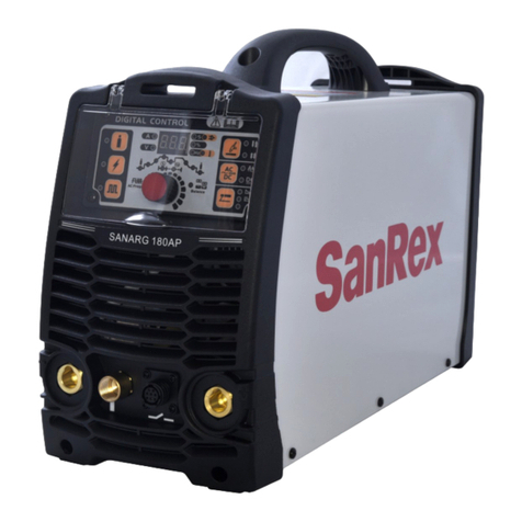
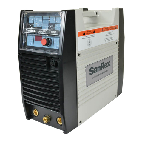
SanRex SANARG 300AP User manual

SanRex
SANARG
300AP
WITH COOLING WATER
PRESSURE SENSOR
AC/DC/AC-SOFT
INVERTER
ARC WELDER
Operators
Manual
Version No: AD Issue Date: MAR 15, 2021
Manual No: K00A0316500


Welcome to the SanRex Family Welding
Team!
Dear Welding Professional,
We would like to take this opportunity to thank you, and congratulate you on procuring a SanRex
SANARG 300AP with cooling water pressure sensor AC/DC STICK Welding Machine.
Welding Professional, now that is a term that we do not take lightly. The welding machine that you
purchased is a full function, portable unit that was designed with the Welding Professional in mind.
The unit is suitable for use as a portable welder on the job site, to a unit utilized in an industrial
manufacturing setting. This unit will perform and is truly a welder for the Professional Welder. As
you review this manual, you will be provided with information regarding the use and functionality of
the unit. What you will not see is information or instruction on “how to weld”, as this appropriately
left to the vast array of Vocational, Trade and other institutions that provide instructional education
in welding.
This manual also contains sections that are dedicated solely to the safety of you and others in the
work area. It is highly recommended that this information be reviewed and that this manual be kept
in a secure but accessible location for reference of these import safety and well-being notices.
Remember, the number one requirement in performing any job is safety.
Sansha Electric of Osaka Japan and its “SanRex” brand name of products has specialized in the
power supply and power semiconductor manufacturing business for over 80 years. With over 55
years producing welding power supplies and over 30 years producing inverter based welding and
plasma cutting power supplies, you can be assured that you have purchased one of the best welding
machines on the market today.
The superior Arc Characteristics that you will experience is achieved through our dedication and
commitment to research and development as well as developing smart solutions for safe, reliable and
environmentally friendly welding machines.
We value long term relationships with our customers and strive to provide the most cost effective
solutions that support this philosophy.
We thank you for choosing SanRex equipment.
SanRex Family Welding Team


INTRODUCTION
PURPOSE OF THIS MANUAL
This manual has been prepared to present the safety, installation/operation and maintenance instructions for
the SanRex SANARG 300AP with cooling water pressure sensor, hereby referred to as 300AP, an AC/DC
Stick and TIG welding machine manufactured by the Sansha Corporation of Osaka, Japan. The manual
contains the information necessary for the Professional Welder to correctly use and operate the 300AP. It is
not the intent of this manual, and does not,instruct or offer information on how to weld.
This operation manual includes an introduction followed by detailed information sections.
The information in this operating manual is generic to this model line of the welding machine and must be
supplemented with application specific data, environment condition (location), electrical input connections,
limitations, and principal safety standards.
SECTION 1 - SAFETY REGULATIONS
AND REQUIREMENTS
This section contains the leading particulars
and descriptions of the welding symbols,
safety, warning instructions; additional
symbols for a complete understanding and
safe use of the equipment are also included.
SECTION 2 – INTRODUCTION AND
DESCRIPTION
This section includes descriptions and
features of the product, V-A curves and the
functional lock diagram of the product.
SECTION 3 - INSTALLATION
RECOMMENDATIONS
Describing the transportation, working
environment, electrical hook-up with
consideration for grounding and high
frequency interference. Also input power,
connections and specifications.
SECTION 4 – OPERATOR CONTROLS,
DIMENSIONS AND OUTLINE
Included in this section is a sequence of
operation, welding process selection, 300AP
attributes and model features and remote
control receptacle specifications.
SECTION 5 – SET-UP FOR BASIC STICK
(SMAW) AND TIG (GTAW)
WELDING
This section shows the basic STICK and
TIG connection set-up for the 300AP from
tank to workpiece.
SECTION 6 -SEQUENCE OF OPERATION
This section describes the sequence to set-up
the machine to perform STICK, TIG and
HF-TIG welding operations.
SECTION 7 – VOLTAGE REDUCTION
DEVICE (VRD)
This section includes information in the
Voltage Reduction device that is built-in to
the unit. This device lowers the Open
Circuit Voltage in STICK welding. This
function is useful in applications where a
high OCV could be dangerous. The 300AP
is shipped from the factory with the VRD
disabled.
SECTION 8 – TROUBLESHOOTING
This section provides information on Power
Source problems and Power Source Error
Codes.
SECTION 9 – ROUTINE MAINTENANCE
This section describes basic maintenance for
the welding power source.
SECTION 10 – PARTS LIST
This section contains the basic schematic,
exploded view and a listing of the spare
parts and order numbers.

Contents
1.0 SAFETY REGULATIONS AND REQUIREMENTS.................................................................. 9
1.01 Notes, Cautions and Warning Annotations.................................................................................. 9
1.02 Safety Recommendations........................................................................................................... 10
1.03 Welding Symbols....................................................................................................................... 11
1.03.01 Safety Symbol Legend.......................................................................................................... 11
1.03.02 Graphic Symbol Legend....................................................................................................... 17
1.04 Safety Precautions....................................................................................................................... 18
1.05 Safe Operation of the Welder and Personal Protection ............................................................. 19
1.05.01 Important Safety Precautions................................................................................................ 19
1.05.02 Electric Shock....................................................................................................................... 20
1.05.03 Gases and Fumes................................................................................................................... 21
1.05.04 Fire and Explosions............................................................................................................... 22
1.05.05 Arc Welding Rays, Noise and Spatter or Slag...................................................................... 23
1.05.06 Gas Cylinders........................................................................................................................ 24
1.06 Reference Publications............................................................................................................... 25
2.0 INTRODUCTION AND DESCRIPTION................................................................................... 27
2.01 General Information................................................................................................................... 27
2.02 Welding Machine Description................................................................................................... 27
2.03 300AP Power Source Features................................................................................................... 27
2.04 Welding Output Voltage and Amperage Curves ....................................................................... 30
2.04.01 300AP V/A Output Curves................................................................................................... 30
2.05 Functional Block Diagram......................................................................................................... 31
3.0 INSTALLATION RECOMMENDATIONS............................................................................... 33
3.01 Transportation Methods............................................................................................................. 33
3.02 Environment............................................................................................................................... 34
3.03 Machine Grounding & High Frequency Interference................................................................ 34
3.03.01 Grounding............................................................................................................................. 34
3.03.02 High Frequency Introduction................................................................................................ 34
3.03.03 High Frequency Interference ................................................................................................ 35
3.04 Location ..................................................................................................................................... 36
3.05 Electrical Input Connections & Requirements .......................................................................... 36
3.05.01 Input Power........................................................................................................................... 36
3.05.02 Fusing.................................................................................................................................... 37
3.05.03 Electrical Input Connections................................................................................................. 38
3.06 Specifications............................................................................................................................. 40
3.06.01 Input/Output.......................................................................................................................... 40
3.06.02 General Information.............................................................................................................. 41
3.07 Duty Cycle................................................................................................................................. 42
4.0 OPERATOR CONTROLS, DIMENSIONS & OUTLINE ......................................................... 43
4.01 Dimensions and Outline............................................................................................................ 43
4.02 Operator Controls, Location and Functionality......................................................................... 43
4.03 14-PIN Remote Control Receptacle........................................................................................... 46
4.04 Parameter Display Panel............................................................................................................ 47
4.05 Function Selection ..................................................................................................................... 51
4.06 Parameter Selection ................................................................................................................... 52
4.07 Internal Parameter Selection...................................................................................................... 53
5.0 SET-UP FOR BASIC STICK (SMAW) AND TIG (GTAW) WELDING................................. 55
6.0 SEQUENCE OF OPERATION................................................................................................... 56
6.01 Stick Welding............................................................................................................................. 58
6.01.01 Stick Welding Sequence with Voltage Reduction Device Disabled .................................... 59

6.01.02 Stick Welding Sequence with Voltage Reduction Device Enabled...................................... 59
6.02 AC or DC HF TIG Welding....................................................................................................... 60
6.03 LIFT TIG Sequence................................................................................................................... 61
6.03.01 Standard Mode...................................................................................................................... 61
6.03.02 Slope Mode........................................................................................................................... 61
6.03.03 Repeat Mode......................................................................................................................... 61
6.04 HF TIG Sequence ...................................................................................................................... 62
6.04.01 Standard Mode...................................................................................................................... 62
6.04.02 Slope Mode........................................................................................................................... 62
6.04.03 Repeat Mode......................................................................................................................... 62
6.04.04 Spot Mode............................................................................................................................. 63
6.05 Waveform Options..................................................................................................................... 63
6.05.01 VR-Current ........................................................................................................................... 63
6.05.02 AC-SOFT Mode.................................................................................................................... 64
6.06 Slope Function........................................................................................................................... 65
6.06.01 2T Slope Function................................................................................................................. 65
6.06.02 4TS Mode Setting................................................................................................................. 65
7.0 VOLTAGE REDUCTION DEVICE (VRD)............................................................................... 66
7.01 VRD Spectifications .................................................................................................................. 66
7.02 Enabling/Disabling VRD........................................................................................................... 66
8.0 TROUBLE SHOOTING.............................................................................................................. 69
8.01 Power Source Problems............................................................................................................. 69
8.02 Power Source Error Codes......................................................................................................... 71
9.0 ROUTINE MAINTENANCE...................................................................................................... 75
9.01 Opening the Enclosure............................................................................................................... 76
10.0 PARTS LIST 300AP ................................................................................................................. 79
10.01 Interconnect Diagram 300AP .................................................................................................. 88
10.02 Exploded View 300AP ............................................................................................................ 90
APPENDIX A..................................................................................................................................... 92


9
SECTION 1- SAFETY REGULATIONS AND REQUIREMENTS
1.0 SAFETY REGULATIONS AND REQUIREMENTS
Throughout this manual, notes, cautions, danger, attention and warnings are used to highlight
important information. These highlights are categorized as follows:
1.01 Notes, Cautions and Warning Annotations
NOTE:An operation, procedure, or background information which requires
additional emphasis or is helpful in efficient operation of the system.
CAUTION: A procedure which, if not properly followed, may cause damage to the
equipment.
WARNING: A procedure which, if not properly followed, may cause injury to the
operator or others in the operating.
DANGER: Procedures, which if not properly followed, may lead to death or serious
injury.
Please read this operating manual thoroughly before utilizing the equipment.
Wherever welding equipment is used, safety is always our concern.
PROTECT yourself and others.

10
1.02 Safety Recommendations
For the purpose of safety, it is recommended that this welding equipment be installed,
maintained, inspected, and repaired by appropriable qualified person or persons who
are well familiarized with welding equipment.
As for safety training, it is recommended to avail yourselves of various seminars
and qualifying examinations for welding engineers and welding technicians
sponsored by the Welding Society, the Welding Engineering Society, and the
headquarters or branch offices of societies or associations concerned.
For the purpose of safety, it is recommended that this welding equipment should be
operated by persons who have sufficient knowledge and skill to understand all safety
precautions and instructions in the Operating Manual and to be able handle the
equipment safely.
After reading this Operating Manual, please store it carefully with guarantee where it
will be made accessible to all personnel dealing with the equipment.
Please call your local distributors, business offices, or service agents if you have
any questions.

11
1.03 Welding Symbols
1.03.01 Safety Symbol Legend
SYMBOL
SOURCE OF
HAZARD
HAZARD HOW TO AVOID
Welding
Electrode Electric Shock
Don’t weld on painted parts.
Remove the surface coating
before you begin welding. Keep
your face away from the welding
plume.
Wiring Electric Shock
Protect welding cables from
sparks, hot metal, open flames,
sharp edges, oil, and grease.
Do not use cables with frayed,
cracked or bare spots in the
insulation. Learn all you can
about safety. Your employer must
provide safety training.
Welding Arc Arc Rays
Required protection varies with
time of exposure, distance from
source, and shielding used.
Follow recommended procedures
in AWS F2.1
Engine Fuel Fire
Develop adequate procedures,
and use proper equipment to do
the job safely.
When required obtain a Hot-
Work Permit (See NFPA 51B).
If relocation is not possible,
protect combustibles with fire
resistant covers
Welding Fumes
and Gases Fumes and Gases
Keep your head out of the fumes.
Do not breathe the fumes. Use
enough ventilation or exhaust at
the arc, or both, to keep fumes
and gases from your breathing
zone and general area
Welding
Electrode and
Wiring Electric Shock
Read all instructions, labels, and
installation manuals before
installing, operating, or servicing
the equipment.
Train all personnel involved in
welding operations to observe
safe electrical work practices
according to OSHA 1910.332.
Do not touch live electrical parts.

12
SYMBOL
SOURCE OF
HAZARD
HAZARD HOW TO AVOID
Chromium and
Nickel Fumes Welding Fumes
Do not breathe fumes and gases.
Keep your head out of the
fumes.
Use enough ventilation or
exhaust at the arc or both to keep
fumes and gases from your
breathing zone and general area
Hazard Distances Ultraviolet
Radiation
Maintain proper distances from
the Arc Ray.
Review the “Safety and Health
Fact Sheet No. 26” from the
AWS for recommendations.
Falling Objects Falling Objects
Be certain that material being
welded or cut is secured from
falling.
Do not permit loose objects near
the edge of overhead structures
Confined Space Fire, Exposure to
Hazardous Air
Contaminants
Determine if special training or a
permit is required to enter the
space.
Open all covers and secure them
from closing.
Test atmosphere for:
(1) suitable oxygen content
(2) combustibles or reactives
(3) toxics
Sparks, Radiation,
Hot Metal,
Slag, Heat Electrical, Thermal
Wear a helmet with filter lens
and cover plate that complies
with ANSI Z87.1 for protection
from radiant energy, flying
sparks, and spatter.
According to ANSI Z49.1 and
OSHA 29 CFR 1910.252,
"Helmets and hand shields shall
protect the face, forehead, neck,
and ears PPE
Hot Metal, Slag,
Arc Rays, Hot
Work Piece Thermal
Use approved helmets or hand
shields that provide protection
for the face, neck, and ears, and
wear a head covering.
Wear approved safety goggles or
safety glasses with side shields,
even under your helmet.
Wear dry, hole-free insulating
gloves.

13
SYMBOL
SOURCE OF
HAZARD
HAZARD HOW TO AVOID
Optical Radiation and
Arc Heat Thermal
Establish a written policy
documenting general safety
requirements for the wearing of
contact lenses. Conduct an eye
hazard evaluation in the
workplace
Cuts, Scrapes, Heat,
Flames, Molten Metal,
Wet Gloves, Insulation
Failure
Mechanical,
Thermal,
Electrical
Gloves should be:
Dry and moisture resistant.
In good condition, no holes or
tears.
Flame resistant.
Electrically and thermally
insulated to suit the process.
Coating of Steel Fumes and
Gases
Obtain the Material Safety Data
Sheets (MSDSs) for all materials
used. Read and understand the
specification for coating type
and coating weights. Find out
what hazardous materials are
present or might be given off by
the coating when it is exposed to
the arc of high temperatures
Reactive Force from
Tools,
Tool Jammed or Coming
Loose
Mechanical
Wear proper head, eye and hand
protection.
Use face shields, safety glasses,
and goggles as appropriate.
Inspect tools before use.
Never use a tool that is in poor
or faulty condition.
Keep all tools in good condition.
Engine-Driven
Generators, power source
Equipment Health Hazard
Reduce the intensity of the
source.
Shield the source where
practical.
Use engineering control
methods, such as room
acoustics, to control noise.
Place Body Between
Welding Electrode and
Work Cables
Electric &
Magnetic
Fields
Do not place your body between
the welding electrode and work
cables. Route cables on the same
side of your body.
Route the welding cables close
together. Secure them together
with tape or cable ties.

14
SYMBOL
SOURCE OF
HAZARD
HAZARD HOW TO AVOID
Hot Metal, Slag, Arc
Rays, Hot Work Piece Thermal
Use approved helmets or hand
shields that provide protection
for the face, neck, and ears, and
wear a head covering.
Wear approved safety goggles or
safety glasses with side shields,
even under your helmet.
Wear dry, hole-free insulating
gloves.
Optical Radiation and
Arc Heat Thermal
Establish a written policy
documenting general safety
requirements for the wearing of
contact lenses. Conduct an eye
hazard evaluation in the
workplace
Cuts, Scrapes, Heat,
Flames, Molten Metal,
Wet Gloves, Insulation
Failure
Mechanical,
Thermal,
Electrical
Gloves should be:
Dry and moisture resistant.
In good condition, no holes or
tears.
Flame resistant.
Electrically and thermally
insulated to suit the process.
Coating of Steel Fumes and
Gases
Obtain the Material Safety Data
Sheets (MSDSs) for all materials
used. Read and understand the
specification for coating type
and coating weights. Find out
what hazardous materials are
present or might be given off by
the coating when it is exposed to
the arc of high temperatures
Reactive Force from
Tools,
Tool Jammed or Coming
Loose
Mechanical
Wear proper head, eye and hand
protection.
Use face shields, safety glasses,
and goggles as appropriate.
Inspect tools before use.
Never use a tool that is in poor
or faulty condition.
Keep all tools in good condition.

15
SYMBOL
SOURCE OF
HAZARD
HAZARD HOW TO AVOID
Optical Radiation and
Arc Heat Thermal
Establish a written policy
documenting general safety
requirements for the wearing of
contact lenses. Conduct an eye
hazard evaluation in the
workplace
Cuts, Scrapes, Heat,
Flames, Molten Metal,
Wet Gloves, Insulation
Failure
Mechanical,
Thermal,
Electrical
Gloves should be:
Dry and moisture resistant.
In good condition, no holes or
tears.
Flame resistant.
Electrically and thermally
insulated to suit the process.
Coating of Steel Fumes and
Gases
Obtain the Material Safety Data
Sheets (MSDSs) for all materials
used. Read and understand the
specification for coating type
and coating weights. Find out
what hazardous materials are
present or might be given off by
the coating when it is exposed to
the arc of high temperatures.
Reactive Force from
Tools,
Tool Jammed or Coming
Loose
Mechanical
Wear proper head, eye and hand
protection.
Use face shields, safety glasses,
and goggles as appropriate.
Inspect tools before use.
Never use a tool that is in poor
or faulty condition.
Keep all tools in good condition.
Engine-Driven
Generators, power source
Equipment Health Hazard
Reduce the intensity of the
source.
Shield the source where
practical.
Use engineering control
methods, such as room
acoustics, to control noise.
Place Body Between
Welding Electrode and
Work Cables
Electric &
Magnetic
Fields
Do not place your body between
the welding electrode and work
cables. Route cables on the same
side of your body.
Route the welding cables close
together. Secure them together
with tape or cable ties.

16
SYMBOL
SOURCE OF
HAZARD
HAZARD HOW TO AVOID
Any Coatings on Base
Metal, Weld Process Fumes and
Gases
Keep your head out of the
fumes.
Do not breathe the fumes.
Use enough ventilation or
exhaust at the arc, or both, to
keep fumes and gases from your
breathing zone and general area
Welding & Cutting Toxic Fumes,
Electric
Shock
Be alert, aware, and focused on
the job and the work area; notice
any changing conditions.
Wear and use only the correct,
approved equipment for the
specific job; be sure it is
properly installed and used
Welding or its Allied
Processes
Pneumatic,
Electrical,
Gases,
Liquid
Employers must develop a
written lockout/tagout program
and procedure.
Employees must be trained in
these procedures, as well as the
purpose and methods of
lockout/tagout.

17
1.03.02 Graphic Symbol Legend
SEC
VRD
%
t
t2
t1
Amperage
Voltage
Hertz (cycles per second)
Frequency
Seconds
Percentage
DC (Direct Current)
Standard Function
AC (Alternating Current)
Slope Function
Spot Function
Slope with Repeat Function
f
Pulse Current Function
Spot Time (GTAW)
Remote Function
Arc Control (SMAW)
Gas Post-Flow
Gas Pre-Flow
Negative
Positive
Gas Input
Gas Output
Impulse Starting
(High Frequency GTAW)
STICK
(Shielded Metal Arc SMAW)
Remote Control
(Panel/Remote)
Voltage Reduction
Device Circuit
Touch Start
(Lift Start GTAW) Protective Ground

18
1.04 Safety Precautions
NOTE:
FOR PROPER USE, PLEASE READ THIS OPERATING MANUAL
THOROUGHLY PRIOR TO UTILIZING THE WELDING MACHINE
The safety precautions described in this Operating Manual will give you the information
necessary for you to handle the equipment safely and prevent any hazard or damage to you or
others.
Although this welding equipment is designed and manufactured taking into account all possible
scenarios, be sure to observe the safety precautions in this Operating Manual when operating this
welding equipment. Not doing so may cause harm to the operator or others, resulting in death or
serious injury.
Improper use of the equipment may cause various levels of damage. In this Operating Manual,
such damages are classified into two ranks by combination of attention attracting symbols and
signal for the purpose of warning indications. These attention attracting symbols and signal
terms have the same meanings as those for warning labels on the equipment.
PROCEDURES NOT PROPERLY FOLLOWED, MAY CAUSE A RISK TO
OPERATORS RESULTING IN MEDIUM OR SLIGHT INJURY AND/ OR
DAMAGE
Serious or light injury includes loss of sight, high temperature and/or low temperature burns,
electric shock, bone fracture, and poisoning which may lead to hospitalization or long-term
hospital stay for treatment. Further, medium and slight injury includes burns, and electric shock,
which do not require hospitalization or long-term visit to hospital stays for treatment. Damage to
objects denotes widespread damage to property or equipment.
DANGER:
PROCEDURES NOT PROPERLY FOLLOWED, MAY LEAD TO DEATH
OR SERIOUS INJURY.

19
1.05 Safe Operation of the Welder and Personal Protection
1.05.01 Important Safety Precautions
To prevent serious injury to the operator or others, be sure to observe the following:
Never allow any unqualified
person to enter the surrounding
area of this welding equipment or
the welding area inadvertently.
Perform any work of power
source on the input side, select
any location, handle and store and
pipe high pressure gases, store
work pieces welded, and treat
wastes in accordance with
legislations and/or regulations,
and your company’s standards.
Although this welding equipment
is designed and manufactured
taking into account safety
adequately, be sure to observe
safety precautions in this
Operating Manual when operating
this welding equipment.
Not doing so may cause fatal
injury to the operator or others,
resulting in death or serious
injury.
Do not use this welding
equipment for applications other
than welding.
Those who use heart pacemakers
should not enter the surrounding
area of this welding equipment in
operation or the welding area
without permission of the doctor.
Welding equipment during
energizing produces a magnetic
field in the surrounding area
which adversely affects the
operation of such pacemakers.
For the purpose of safety, it is
recommended that this welding
equipment should be installed,
maintained, inspected, and
repaired by appropriately
qualified personnel or persons
who are well familiarized with
welding equipment.
For the purpose of safety, it is
recommended that this welding
equipment should be operated by
persons who have enough
knowledge and skill to understand
all safety precautions and
instructions in the Operating
Manual and to handle the
equipment safely.

20
1.05.02 Electric Shock
To prevent electric shock, be sure to observe the following precaution:
Touching any parts that are
electrically “live” or “hot” may
cause fatal electric shock or
burns.
Have a qualified electrician
connect the Welding Power
Source. Check the enclosure,
base metal and jig that they are
electrically connected in
ordnance with local
regulations. (Electrical
Facilities Technical Standards)
Before installing, maintaining,
or inspecting this welding
equipment, leave the
equipment for over 5 minutes
after turning off power supply
at the distribution panel switch.
Capacitors built-in may be
electrically charged even after
the power has been switched
off.
Before performing works,
make sure that no charging
voltage should be applied to
such parts.
Do not use cables which have
insufficient capacity, are
damaged, or in which any
conductor is exposed.
Tighten cable connections
securely and insulate properly.
Do not operate with welding
equipment with its cover or
enclosure loose or removed.
Do not wear damaged, torn or
wet gloves. Always wear dry
insulated gloves.
Use a lifeline harness when
performing works at any high
elevations.
Carry out maintenance and
inspection periodically and use
it after the repair of any and all
damaged parts.
Turn off both the Mains
ON/OFF switch on equipment
and the distribution panel
switch when not in use.
This manual suits for next models
1
Table of contents
Other SanRex Welding System manuals
Popular Welding System manuals by other brands

Linde
Linde MSI 350 puls Kompakt operating instructions

Rothenberger Industrial
Rothenberger Industrial ROXY KIT ECO manual

Forney
Forney EASY WELD 100 ST operating manual

Image Industries
Image Industries Smartweld SW1200 Operation manual

Advance Welding
Advance Welding ACT 2 operating manual

Cebora
Cebora EVO 160 M instruction manual