Page 5
2. Your Safety
This guide is for the installation of the motor used in the Isodrive systems after the canopy/rangehood or
bathroom extraction grill has been mounted on the wall or ceiling. (Refer to canopy/rangehood or bathroom
extraction unit installation manual).
NOTE: All PVC pipe and SteelFlex™ducting measurements are referring to inside measurements, unless
otherwise mentioned..
Motor Features
• Universal mounting, all position with IPX4 degree of weather protection.
• Patented anti water intrusion system.
• Super quiet, long vane, backward curved centrifugal fan.
• Airow is dependant on installation and the ducting used. Using a single 150mm SteelFlex™duct, you
should attain up to 650m3/hr depending on the ducting installation. The use of a smaller than 125mm
pipe would result in a loss of airow.
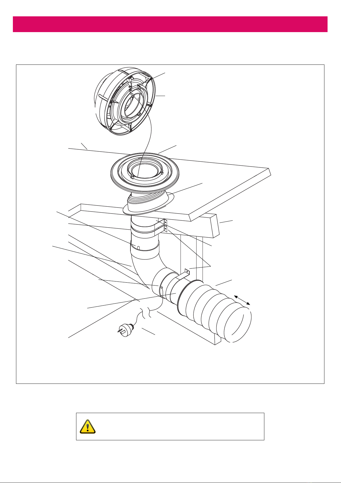
• Simple installation: The motor mounts onto a 100mm PVC pipe for ultimate strength and allows for easy
Dektite roof sealing.
• Industrial quality motor and fan made in Germany and rated at 40,000 hours.
• Motor is a high eciency PSC type and rated at 62W costing around the same as a 60W light globes to run.
• WARRANTY 10 YEARS return to manufacturer. Covers faulty manufacturing or components. It does not
cover normal wear and tear, chemical or storm damage etc.
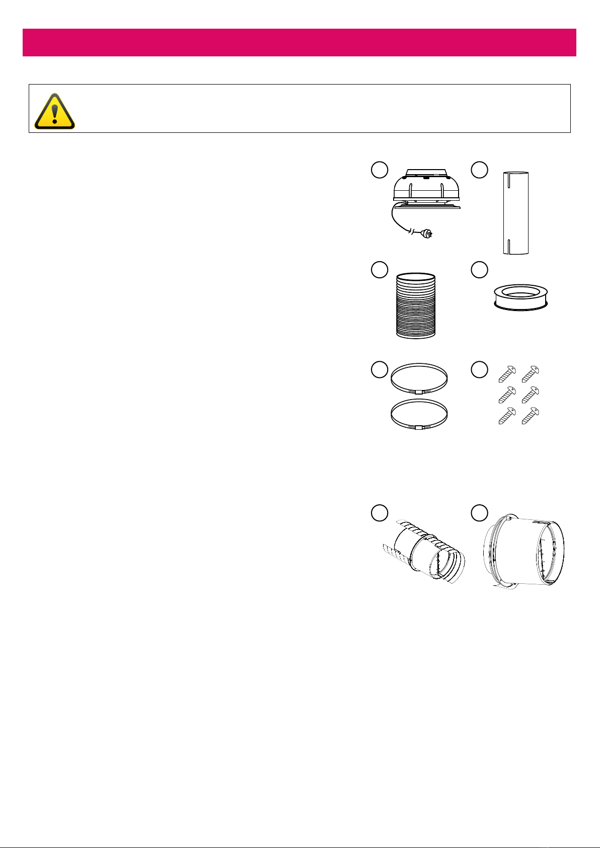
General Notes on Installation and Use
This fan unit is designed to be installed using 100mm PVC pipe as the initial connection duct to the fan module,
and is supplied with a 100mm PVC pipe to 150mm SteelFlex™duct bell-mouth adaptor.
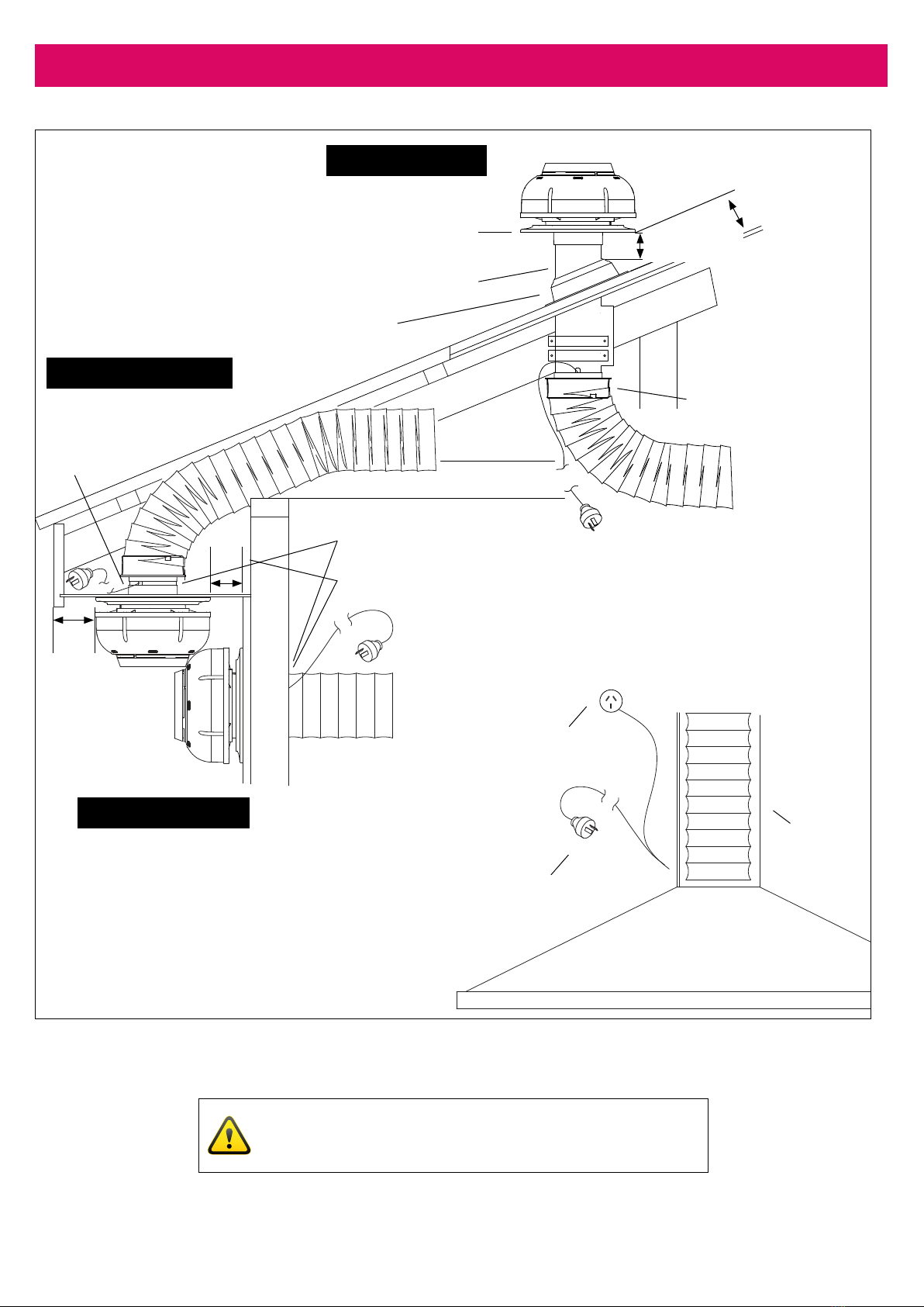
This fan is suitable for connection to ducting runs with a minimum inlet area of 11,000mm2. Ducting runs should
be more than 2 metres away from the unit and no more than 4-5 metres (check with supplier if longer duct
length required). SteelFlex™ducting must be extended suciently to present a smooth air passage with bends
of at least the radius of twice the diameter of the duct. Excessive bends in the ducting will compromised
extraction.
WARNING: The rangehood must not be ducted into a wall cavity or a ceiling space, where a build up of grease
can occur and become a potential re risk. This will void your warranty.
NOTE:Fan module and dual foil Steelex™duct are acoustically matched. Use of semi-rigid or rigid ducting will
result in increased noise and may void warranty. See installation instruction notes ‘Why Schweigen SteelFlex™
Safety Duct’.
Recommended Installation Distance
Isodrive 650 motor, recommended minimum 3 metres (approx.) of SteelFlex™ducting and with at least
two bends.
NOTE: Installation closer than this distance may result in higher noise level. Maximum duct length is 4 to 5
metres. Check with supplier if longer duct length is required. Do not reduce the duct size at any time and
avoid sharp bends.