Schweitzer Engineering Laboratories SEL-734W User manual

SEL-734W and SEL Wireless Current SensorInstruction Manual
*PM734W-01*
SEL-734W and SEL-WCS
Capacitor Bank Control and
SEL Wireless Current Sensors
Field Reference Guide
20191029

SEL-734W and SEL Wireless Current Sensor Field Reference Guide Date Code 20191029
© 2019 by Schweitzer Engineering Laboratories, Inc. All rights reserved.
All brand or product names appearing in this document are the trademark or registered trademark of their respective holders. No SEL trademarks
may be used without written permission.
SEL products appearing in this document may be covered by U.S. and Foreign patents. Schweitzer Engineering Laboratories, Inc. reserves all
rights and benefits afforded under federal and international copyright and patent laws in its products, including without limitation software,
firmware, and documentation.
The information in this document is provided for informational use only and is subject to change without notice. Schweitzer Engineering
Laboratories, Inc. has approved only the English language document.
This product is covered by the standard SEL 10-year warranty. For warranty details, visit selinc.com or contact your customer service
representative. PM734W-01

Date Code 20191029 Field Reference Guide SEL-734W and SEL Wireless Current Sensor
SEL-734W and SEL Wireless Current SensorInstruction Manual Table of Contents
List of Tables.............................................................................................................................................................................. iii
List of Figures.............................................................................................................................................................................v
Preface..........................................................................................................................................................................................vii
Overview.............................................................................................................................................................. .vii
Safety Information ............................................................................................................................................... .vii
General Information................................................................................................................................................ix
Section 1: Introduction and Specifications
Overview...............................................................................................................................................................1.1
System Features and Benefits ...............................................................................................................................1.2
Product Overview .................................................................................................................................................1.3
SEL-734W Overview............................................................................................................................................1.4
SEL-WCS Specifications......................................................................................................................................1.6
SEL-734W Specifications.....................................................................................................................................1.7
Section 2: Installation
Overview...............................................................................................................................................................2.1
Dimensions ...........................................................................................................................................................2.1
Installations...........................................................................................................................................................2.2
Getting Started ......................................................................................................................................................2.6
Section 3: Applications
Single-Phase Measurement and Ganged Switching .............................................................................................3.1
Three-Phase Measurements and Ganged Switching.............................................................................................3.1
Section 4: SEL-734W
Overview...............................................................................................................................................................4.1
Capacitor Bank Control ........................................................................................................................................4.1
Front-Panel Operations .........................................................................................................................................4.3
Power System Quantity Measurements ................................................................................................................4.5
Section 5: SEL-WCS
Overview...............................................................................................................................................................5.1
Current Measurements ..........................................................................................................................................5.1
Section 6: Differences Between the SEL-734B and the SEL-734W
Overview...............................................................................................................................................................6.1
Capacitor Bank Control Strategies........................................................................................................................6.1
Metering................................................................................................................................................................6.2
Power Quality and Event Analysis .......................................................................................................................6.2
Section 7: Testing and Troubleshooting
Appendix A: Field Reference Guide Versions
Field Reference Guide .........................................................................................................................................A.1

This page intentionally left blank

Date Code 20191029 Field Reference Guide SEL-734W and SEL Wireless Current Sensor
SEL-734W and SEL Wireless Current SensorInstruction Manual List of Tables
Table 2.1 Socket Stab Configurations .........................................................................................................2.3
Table 4.1 Front-Panel LED Descriptions ....................................................................................................4.4
Table 5.1 SEL-WCS Typical Update Period Versus Line Current .............................................................5.1
Table 5.2 Frequency Channels ....................................................................................................................5.2
Table 5.3 Phase Identification Configuration ..............................................................................................5.3
Table 6.1 SEL-734W and SEL-734B Control Strategy Comparison ..........................................................6.1
Table 7.1 Troubleshooting and Common Problems ....................................................................................7.1
Table A.1 Field Reference Guide Revision History....................................................................................A.1

This page intentionally left blank

Date Code 20191029 Field Reference Guide SEL-734W and SEL Wireless Current Sensor
SEL-734W and SEL Wireless Current SensorInstruction Manual List of Figures
Figure 1.1 SEL-734W and SEL-WCS Capacitor Bank Control System ......................................................1.1
Figure 1.2 System Overview.........................................................................................................................1.2
Figure 1.3 SEL-WCS Key Components .......................................................................................................1.3
Figure 1.4 SEL-734W Front Panel Overview...............................................................................................1.4
Figure 2.1 4-Jaw Socket-Based Enclosure Dimensions................................................................................2.1
Figure 2.2 SEL-WCS Dimensions ................................................................................................................2.2
Figure 2.3 Rear of a Socket-Based Enclosure...............................................................................................2.3
Figure 2.4 SEL-734W Required System Grounding ....................................................................................2.4
Figure 3.1 Single-Phase Application ............................................................................................................3.1
Figure 3.2 Three-Phase Application .............................................................................................................3.1
Figure 4.1 SEL-734W ...................................................................................................................................4.2
Figure 4.2 SEL-734W DIP Switch Settings..................................................................................................4.3
Figure 5.1 Control (DIP) Switch Configurations..........................................................................................5.2

This page intentionally left blank

Date Code 20191029 Field Reference Guide SEL-734W and SEL Wireless Current Sensor
SEL-734W and SEL Wireless Current SensorInstruction Manual Preface
Overview
The SEL-734W Capacitor Bank Control is based on the SEL-734 Advanced
Metering System platform. Devices ship with an outdoor-rated enclosure and are
programmed with control strategies via SEL design templates.
The SEL-734W Field Reference Guide provides a general overview of the
SEL-734W and describes the procedures for installation as a capacitor bank con-
trol. This guide also provides troubleshooting and testing methods.
The SEL-734W Data Sheet describes the SEL-734W and SEL-WCS system, the
features and control strategies of the SEL-734W, as well as interface.
The SEL-734W ACSELERATOR QuickSet Design Template Guide describes the
operation, details the settings, and contains logical diagrams for developers.
The SEL-734 Instruction Manual details all other features available in the
SEL-734 device, including metering, power quality, and communications.
Safety Information
Dangers, Warnings, and Cautions
This manual uses three kinds of hazard statements, defined as follows:
Safety Symbols
The following symbols are often marked on SEL products.
DANGER
Indicates an imminently hazardous situation
that, if not avoided, will result in death or seri-
ous injury.
WARNING
Indicates a potentially hazardous situation
that, if not avoided, could result in death or seri-
ous injury.
CAUTION
Indicates a potentially hazardous situation
that, if not avoided, may result in minor or mod-
erate injury or equipment damage.
CAUTION
Refer to accompanying documents.
ATTENTION
Se reporter à la documentation.
Earth (ground) Terre
Protective earth (ground) Terre de protection

viii
SEL-734W and SEL Wireless Current Sensor Field Reference Guide Date Code 20191029
Preface
Safety Information
Safety Marks
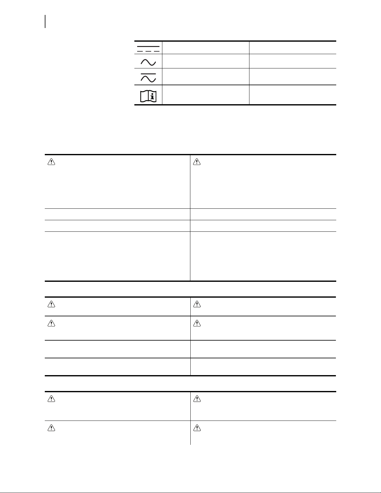
The following statements apply to this device.
Direct current Courant continu
Alternating current Courant alternatif
Both direct and alternating current Courant continu et alternatif
Instruction manual Manuel d’instructions
General Safety Marks
CAUTION
There is danger of explosion if the battery is incorrectly replaced.
Replace only with Rayovac no. BR2335 or equivalent recommended by
manufacturer. See Owner's Manual for safety instructions. The battery
used in this device may present a fire or chemical burn hazard if mis-
treated. Do not recharge, disassemble, heat above 100°C or incinerate.
Dispose of used batteries according to the manufacturer’s instructions.
Keep battery out of reach of children.
ATTENTION
Une pile remplacée incorrectement pose des risques d’explosion. Rem-
placez seulement avec un Rayovac no BR2335 ou un produit équivalent
recommandé par le fabricant. Voir le guide d’utilisateur pour les instruc-
tions de sécurité. La pile utilisée dans cet appareil peut présenter un
risque d’incendie ou de brûlure chimique si vous en faites mauvais
usage. Ne pas recharger, démonter, chauffer à plus de 100°C ou inciné-
rer. Éliminez les vieilles piles suivant les instructions du fabricant. Gardez
la pile hors de la portée des enfants.
For use in Pollution Degree 2 environment. Pour l'utilisation dans un environnement de Degré de Pollution 2.
Ambient air temperature shall not exceed 40°C (104°F). La température ambiante de l'air ne doit pas dépasser 40°C (104°F).
Terminal Ratings Valeurs nominales des bornes
Wire Material
Copper
Matériau de fil
Cuivre
Tightening Torque
Other Terminal Blocks: 0.8 Nm (7.0 in-lb)
Couple de Serrage
Autres borniers : 0,8 Nm (7,0 livres-pouce)
Hazardous Locations Safety Marks
WARNING – EXPLOSION HAZARD
Open circuit before removing cover.
AVERTISSEMENT – DANGER D'EXPLOSION
Ouvrir le circuit avant de déposer le couvercle.
WARNING – EXPLOSION HAZARD
Substitution of components may impair suitability for Class I, Division 2.
AVERTISSEMENT – DANGER D'EXPLOSION
La substitution de composants peut détériorer la conformité à Classe I,
Division 2.
Operating Temperature Range: –40°C to +85°C (–40°F to +185°F). Plage de température de fonctionnement : –40°C à +85°C
(–40°F à +185°F).
Hazardous Locations Operating Temperature Range: –20°C to
+40°C (–4°F to +104°F).
Emplacements Plage de température de fonctionnement
d’emplacements dangereux : –20°C à +40°C (–4°F à +104°F).
Other Safety Marks (Sheet 1 of 2)
DANGER
Disconnect or de-energize all external connections before opening this
device. Contact with hazardous voltages and currents inside this device
can cause electrical shock resulting in injury or death.
DANGER
Débrancher tous les raccordements externes avant d’ouvrir cet appareil.
Tout contact avec des tensions ou courants internes à l’appareil peut
causer un choc électrique pouvant entraîner des blessures ou la mort.
DANGER
Contact with instrument terminals can cause electrical shock that can
result in injury or death.
DANGER
Tout contact avec les bornes de l’appareil peut causer un choc électrique
pouvant entraîner des blessures ou la mort.

ix
Date Code 20191029 Field Reference Guide SEL-734W and SEL Wireless Current Sensor
Preface
General Information
General Information
Trademarks
All brand or product names appearing in this document are the trademark or reg-
istered trademark of their respective holders. No SEL trademarks may be used
without written permission.
Trademarks appearing in this manual are shown in the following table.
WARNING
Use of this equipment in a manner other than specified in this manual
can impair operator safety safeguards provided by this equipment.
AVERTISSEMENT
L’utilisation de cet appareil suivant des procédures différentes de celles
indiquées dans ce manuel peut désarmer les dispositifs de protection
d’opérateur normalement actifs sur cet équipement.
WARNING
Have only qualified personnel service this equipment. If you are not
qualified to service this equipment, you can injure yourself or others, or
cause equipment damage.
AVERTISSEMENT
Seules des personnes qualifiées peuvent travailler sur cet appareil. Si
vous n’êtes pas qualifiés pour ce travail, vous pourriez vous blesser avec
d’autres personnes ou endommager l’équipement.
WARNING
This device is shipped with default passwords. Default passwords should
be changed to private passwords at installation. Failure to change each
default password to a private password may allow unauthorized access.
SEL shall not be responsible for any damage resulting from unautho-
rized access.
AVERTISSEMENT
Cet appareil est expédié avec des mots de passe par défaut. A l’installa-
tion, les mots de passe par défaut devront être changés pour des mots
de passe confidentiels. Dans le cas contraire, un accès non-autorisé á
l’équipement peut être possible. SEL décline toute responsabilité pour
tout dommage résultant de cet accès non-autorisé.
CAUTION
Equipment components are sensitive to electrostatic discharge (ESD).
Undetectable permanent damage can result if you do not use proper
ESD procedures. Ground yourself, your work surface, and this equipment
before removing any cover from this equipment. If your facility is not
equipped to work with these components, contact SEL about returning
this device and related SEL equipment for service.
ATTENTION
Les composants de cet équipement sont sensibles aux décharges élec-
trostatiques (DES). Des dommages permanents non-décelables peuvent
résulter de l’absence de précautions contre les DES. Raccordez-vous cor-
rectement à la terre, ainsi que la surface de travail et l’appareil avant
d’en retirer un panneau. Si vous n’êtes pas équipés pour travailler avec
ce type de composants, contacter SEL afin de retourner l’appareil pour
un service en usine.
CAUTION
Use of controls or adjustments, or performance of procedures other
than those specified herein, may result in hazardous radiation exposure.
ATTENTION
L’utilisation de commandes ou de réglages, ou l’application de tests de
fonctionnement différents de ceux décrits ci-après peuvent entraîner
l’exposition à des radiations dangereuses.
CAUTION
Changes or modifications not expressly approved by the party responsi-
ble for compliance could void the user's authority to operate the equip-
ment.
ATTENTION
Les changements ou modifications qui ne sont pas expressément
approuvés par l'autorité responsable de se prononcer sur la conformité
pourraient annuler le pouvoir de l'usager à actionner l'équipement.
CAUTION
Connect only 120 Vac nominal to the SEL-734W socket stab VOLTAGES con-
nector.
ATTENTION
Connecter seulement 120 Vca nominal au connecteur de prise VOLTAGES
(Tensions) du SEL-734W
CAUTION
Ground the SEL-734W Capacitor Bank Control cabinet chassis before
making any other connections to the cabinet.
ATTENTION
Mettre à la terre le châssis de l'armoire du Contrôle de batterie de con-
densateurs SEL-734W avant de faire toute autre connexion à l'armoire.
Other Safety Marks (Sheet 2 of 2)
SEL Trademarks
ACSELERATOR QuickSet®SELOGIC®

x
SEL-734W and SEL Wireless Current Sensor Field Reference Guide Date Code 20191029
Preface
General Information
Technical Support
We appreciate your interest in SEL products and services. If you have questions
or comments, please contact us at:
Schweitzer Engineering Laboratories, Inc.
2350 NE Hopkins Court
Pullman, WA 99163-5603 U.S.A.
Tel: +1.509.338.3838
Fax: +1.509.332.7990
Internet: selinc.com/support
Email: [email protected]

Date Code 20191029 Field Reference Guide SEL-734W and SEL Wireless Current Sensor
SEL-734W and SEL Wireless Current SensorInstruction Manual SECTION 1
Introduction and Specifications
Overview
The SEL-734W Capacitor Bank Control pairs with SEL Wireless Current Sen-
sors (WCS) to provide capacitor bank control for distribution systems. The sys-
tem uses an SEL-WCS to measure current and a control power transformer
(CPT) to measure voltage. It uses the measured quantities to operate a set of
capacitor banks. The system helps improve power factor, provides VAR support,
and improves the voltage profile by inserting or removing the capacitor bank
from the distribution system. The system ultimately helps reduce line losses
because of reactive power consumption and increases system capacity.
The SEL-WCS is a line-powered device that measures current. The single shot-
gun-style hot stick installation and clamping mechanism allows for a quick
installation that firmly attaches the sensor onto an overhead conductor. The
SEL-WCS wakes up periodically, measures current (rms), computes harmonic
content up to the 15th harmonic, and transmits the data to the SEL-734W.
Figure 1.1 SEL-734W and SEL-WCS Capacitor Bank Control System

1.2
SEL-734W and SEL Wireless Current Sensor Field Reference Guide Date Code 20191029
Introduction and Specifications
System Features and Benefits
The SEL-734W processes data from one or three SEL-WCS devices and from the
CPT to implement a variety of cap bank control strategies. The SEL-734W uses
current measured independently from three SEL-WCS devices and one measured
voltage to provide three-phase switching decisions and monitoring. For this
application, the SEL-734W creates the other two voltage phases of equal magni-
tude to the measured phase, but at 120 and –120 degrees rotation relative to the
measured phase.
The SEL-734W continuously samples voltage on the power lines (via post-line
sensor or a single-phase CPT) and receives data from the SEL-WCS devices.
Combining the data from the SEL-WCS and the voltage measurements, the
SEL-734W accurately measures the phase angle between the system voltage and
the current. The SEL-734W uses both the measured voltage and the current
received from the SEL-WCS to calculate real and reactive power. The
SEL-734W computes other quantities such as power factor and total harmonic
distortion by using the received data from the SEL-WCS along with the mea-
sured voltage.
System Features and Benefits
The SEL-734W and SEL-WCS system measures voltage from a CPT (or line
post sensor) and currents to make switching decisions for a variety of advanced
control strategies such as VAR, current, and power factor. The SEL-WCS sends
data periodically to the SEL-734W. The SEL-734W uses the received data along
with measured voltage from the CPT to compute the quantities that allow the
SEL-734W to make switching decisions, provide metering information and
power quality information, and store events and load profiles. Additional control
strategies include voltage and time-of-day.
The SEL-734W and SEL-WCS system measures one voltage and three currents
from the SEL-WCS devices to provide three-phase switching decisions and mon-
itoring.
Figure 1.2 System Overview
Control Power
Transformer
A
B
C
N
Capacitor
Bank
Three-Phase
Capacitor Bank
Switch
SEL-734W
WCS_A
WCS_B
WCS_C

1.3
Date Code 20191029 Field Reference Guide SEL-734W and SEL Wireless Current Sensor
Introduction and Specifications
Product Overview
Product Overview
SEL-WCS Product Overview
Figure 1.3 depicts the key components of the SEL-WCS. Each SEL-WCS
mounts onto and monitors the line current on one phase. The SEL-WCS periodi-
cally sends the load data information, including the harmonics, to an SEL-734W.
Shotgun Stick Loop and Spring
The shotgun stick loop and the spring simplify installation on overhead lines and
hold the SEL-WCS in position. See SEL-WCS for more information.
Current Transformer (CT)
The SEL-WCS split-core CT harvests energy to power the device and accurately
measures line current and harmonics of the current.
Integrated Radio
The 900 MHz radio module is mounted inside the SEL-WCS cone for environ-
mental protection. The radio communicates to an SEL-734W to transmit line
data.
Control (DIP) Switches
The control (DIP) switches inside the housing allow easy selection of the identifi-
cation of each sensor. An SEL-WCS has a set of four control (DIP) switches for a
network ID, two control (DIP) switches for a phase ID, and a single control (DIP)
switch that determines whether an SEL-WCS sends the harmonic content infor-
mation to the SEL-734W. Sending harmonics requires more energy, so the time
between updates is greater if you configure the sensor to send harmonics.
Figure 1.3 SEL-WCS Key Components
Shotgun Stick Loop
Current Transformer
Twistlock Housing
for Setting Access
Omnidirectional Antenna for
the Radio Transmitter
Control (DIP)
Switch Bank
Spring for Secure Installation

1.4
SEL-734W and SEL Wireless Current Sensor Field Reference Guide Date Code 20191029
Introduction and Specifications
SEL-734W Overview
SEL-734W Overview
SEL-734W Front Panel
This section describes the general front-panel functionality of the SEL-734W.
The function of front-panel LEDs and pushbuttons are factory-programmed.
Blank labels shipped with the device can be used to indicate new functionality.
Figure 1.4 depicts the front panel of the SEL-734W with default labels installed
on the standalone device.
ENABLED LED
This LED shows the diagnostics status of the SEL-734W. An illuminated
ENABLED LED indicates that the SEL-734W is operating properly. If the ENABLED
LED turns off, the SEL-734W requires service.
Configurable LEDs and Pushbuttons
All front-panel LEDs, except for the ENABLED LED, are configurable. The
SEL-734W has four control pushbuttons and one RESET button. Custom labels on
the front panel and settings in the device define the functionality of the pushbut-
tons and LEDs. Refer to the SEL-734W ACSELERATOR QuickSet Design Template
Guide for details on the functionality of the capacitor bank control program.
Test Front-Panel LEDs
Press the RESET button to illuminate all front-panel LEDs for testing. This push-
button is configurable and performs other functions for capacitor bank control.
Refer to the SEL-734W Template Reference Guide for details on the programmed
functionality of the RESET pushbutton.
Figure 1.4 SEL-734W Front Panel Overview

1.5
Date Code 20191029 Field Reference Guide SEL-734W and SEL Wireless Current Sensor
Introduction and Specifications
SEL-734W Overview
Menu Pushbuttons
The menu pushbuttons provide access to the front-panel menu and are not config-
urable. You can use the menu to perform the following tasks:
➤View the status and diagnostics of the SEL-734W
➤View metering data
➤View and change device settings
➤View event data
Model, Options, and Accessories
Models
The SEL-734W is the model number for the wireless capacitor bank control.
You can select options for a 15 V accessory power supply as well as options for
one or three SEL-WCS devices.
The SEL-WCS model number is SEL-8340. There are presently no configurable
options for the SEL-8340.
Accessories
Accessory Part Number
EIA-232 to USB Communications Cable Refer to the online MOT or contact an
SEL representative or CSR for ordering
information.
Pole Mounting Straps (9.375–12.25 inches) 915900448
Socket-Base Compact Enclosure Locking Ring 915900302

1.6
SEL-734W and SEL Wireless Current Sensor Field Reference Guide Date Code 20191029
Introduction and Specifications
SEL-WCS Specifications
Compliance
Designed and manufactured under an ISO 9001 certified quality
management system
General
Operating Temperature
–40° to +85°C (–40° to +185°F)
Storage Temperature
–40° to +85°C (–40° to +185°F)
Operating Environment
Pollution Degree: 2
Relative Humidity: 5%–95%, noncondensing
Maximum Altitude: 2000 m
Ingress Protection
IP67
Clamp Range (SEL WCS)
6.35 mm to 31.75 mm (0.25 in to 1.25 in)
Dimensions
141.7 mm diameter x 177.0 mm height (5.58 inch diameter x 6.97 inch height)
Weight
Wireless Current Sensor: 0.85 kg (1.9 lb)
Overvoltage
Category III
Insulation Class
Class III
System
Power System Frequency Range
45–65 Hz
Typical Update Period vs Line Current (See
Table 5.1
)
Load Magnitude and Phase Measurement Accuracies
0
0.5
1
1.5
2
2.5
3
3.5
4
4.5
5
5 200 400 600 800 1000
+/– % Error
Amperes rms
Mag Error
0
1
2
3
4
5
6
7
8
9
10
5 100 200 300 400 500 600 700 800 900 1000
+/– Degrees Error
Amperes rms
Degrees Error (Single Phase)
Maximum Voltage
38 kV (L-L)
Maximum Steady-State Load Current
1000 A (Thermal Rating)
Maximum Fault Current
25 kA for 10 cycles
Power
Minimum Load Current
2A
Radio System
Frequency Band
902–928 MHz ISM band (U.S.A, Canada)
SEL WCS
TX Power (Effective Isotropic Radiated Power)
50 mW (17 dBm) peak,
40 mW (16 dBm) typical
Modulation
FSK
Link Range
1,500 ft line-of-sight
Type Tests
Electromagnetic Compatibility Emissions
Radiated: 47 CFR Part 15.109
Class A
Electromagnetic Compatibility Immunity
Electrostatic Discharge: IEC 61000-4-2:2008
IEEE C37.90.3-2001
Discharges:
Indirect: ±8 kV
Contact: ±8 kV
Air: ±15 kV
Radiated: IEEE C37.90.2-2004
20 V/mrms; 80 MHz to 1 GHz
>35 V/mrms with 80% 1 kHz sine wave
modulation
Conducted: IEC 61000-4-6:2008
10 Vrms; 150 kHz to 80 MHz
80% 1 kHz sine wave modulation
Power Frequency Magnetic
Field:
IEC 61000-4-8:2009
100 A/m; 50/60 Hz; 60 s
1000 A/m; 50/60 Hz; 1–3 s
0
1
2
3
4
5
6
7
8
9
10
5 100 200 300 400 500 600 700 800 900 1000
+/– Degrees Error
Amperes rms
Degrees Error (3-Phase)

1.7
Date Code 20191029 Field Reference Guide SEL-734W and SEL Wireless Current Sensor
Introduction and Specifications
SEL-734W Specifications
Environmental
Cold: IEC 60068-2-1:2007
Cold Profile Ad; –40°C; 16 hours;
operational
Dry Heat: IEC 60068-2-2:2007
Dry Heat Profile Bd; +85°C; 16 hours;
operational
Damp Heat; Cyclic: IEC 60068-2-30:2005
Damp Heat Profile Db; +25° to +55°C;
relative humidity 93%; 6 cycles
Vibration: IEC 60255-21-1:1988
Class 1 Vibration Endurance
Class 2 Vibration Response
Shock and Bump: IEC 60255-21-2:1988
Class 1 Shock Withstand
Class 1 Bump
Class 2 Shock Response
Seismic: IEC 60255-21-3:1993
Class 2 Quake Response
Table 5 Certifications by Country
Country Authority Reference
U.S.A. FCC R34-900WCS
Canada IC 4468A-900WCS
Compliance
Designed and manufactured under an ISO 9001 certified quality
management system
General
Frequency and Rotation
60/50 Hz system frequency must be specified at time of order. ABC/
ACB phase rotation is user settable.
Frequency tracking range: 45 to 65 Hz
(V
Arequired for frequency tracking).
Power Supply
Continuous Operating Limits
125/250 Volt Supply: 85–264 Vac (50/60 Hz)
85–275 Vdc
VA Rating: <40 VA/15 W maximum
<20 VA/7 W typical
Interruption (IEC 60255-11:1979)
100 ms at 250 Vac/Vdc
50 ms at 125 Vac/Vdc
Ripple (IEC 60255-11:1979): 5% for dc inputs
Terminal Voltage Dropout: <40 V within 1 minute of power removal
Rated Insulation Voltage
(IEC 60664-1:2002): 300 Vac
Dielectric Test Voltage: 2.8 kVdc
Rated Impulse Voltage
(IEC 60664-1:2002): 4000 V
Radio System
SEL-734W Receiver Card
Antenna Connector: SMA, 50
RX Sensitivity (1% Error
Rate): –85 dBm
15 Vdc Integrated Power Supply
Continuous Operating Limits
Rated Input Voltage: 110–240 Vac (50/60 Hz)
110–250 Vdc
Input Voltage Range: 85–264 Vac (50/60 Hz)
85–275 Vdc
Input Current: <1 A at 85 Vac
<1 A at 85 Vdc
Output Voltage: 15 Vdc ±5% for accessories, as power
supply only
Output Current: 2.75 A for accessories, as power supply only
Ride-Through Performance (With a 25 W Auxiliary Load)
120 Vac Input:
125 Vdc Input:
50 ms
20 ms
Safety
Isolation Rating: 2.5 kVac minimum at 60 Hz
Insulation Rating: 300 Vrms (IEC 60664-2:2002)
Impulse Rating: 4 kVpk (1.2/50 µs per IEC 60664-1:2002)
Overvoltage Category: II (IEC 60664-1:2000)
Insulation Type: Reinforced for Input-to-Output
(IEC 60664-1:2000)
Basic for Input-to-Input
(IEC 60664-1:2000)
Compact Enclosure Output Contacts
Output ratings were determined with IEC 60255-23:1994, using the
simplified method of assessment.
Make Rating: 250 Vdc, 7.2 kVA (Cos theta = 1), 30 A
per IEEE C37.90-1989
Carry: 8 A at 120 Vac, 50/60 Hz
Durability: >100,000 cycles for:
Three motor-operated switches as high as
1/4 HP each
Three solenoid-operated switches as high
as 12 A each
Pickup/Dropout Time: <35 ms
Maximum Operating
Voltage: 240 V
Rated Insulation Voltage: 300 V

1.8
SEL-734W and SEL Wireless Current Sensor Field Reference Guide Date Code 20191029
Introduction and Specifications
SEL-734W Specifications
Physical
Operating Temperature
SEL-734W Device: IEC 60068-2: –40° to +85°C
(–40° to +185°F)
LCD: –20° to +70°C (–4° to +158°F)
Device in Compact Enclosure With Integrated 15 Vdc Power Supply
0 W of Accessories: –40° to +65°C (–40° to +149°F)
15 W of Accessories: –40° to +60°C (–40° to +140°F)
40 W of Accessories: –40° to +50°C (–40° to +122°F)
Without Direct Sunlight: Increase max. temperatures by 15°C (27°F)
Operating Environment
Pollution Degree: 2 (SEL-734W Device)
Maximum Altitude: 2000 m
Maximum Humidity: 95% RH
Dimensions
SEL-734W Device
Dimensions: 5.7" x 6.63" x 7.56"
Compact Enclosure Exterior
Dimensions: 13.7" x 11.8" x 8.0"
Weight
4-Jaw Compact Enclosure
Model:
8.8 kg (19.4 lb)
(including SEL-2401 and SEL-3060)
Dielectric Test
Voltage Inputs: 2.2 kVac for 1 s
Optoisolated Inputs and
Output Contacts: 2.2 kVac for 1 s
AC Power Supply: 3.11 kVdc for 1 s
Type Tests
Electromagnetic Compatibility Immunity
Surge Withstand Capability: IEEE C37.90.1-2002 Elec. Relays
2.5 kV oscillatory, 4 kV fast transient
IEC 60255-22-1:2007
2.5 kV peak common, 2.5 kV peak
differential mode, 1.0 kV peak common
mode on communications ports
Power Frequency Magnetic
Field Immunity:
IEC 61000-4-8:2009
1000 A/m for 3 seconds, 100 A/m for
1minute
Pulse Magnetic Field
Immunity: IEC 61000-4-9:1993, 1000 A/m
Electrostatic Discharge
Immunity:
IEC 61000-4-2:2008
Elec. disturbance, Section 2: ESD,
Severity Level: 4
IEC 60255-22-2:2008
Elec. disturb. Section 2: ESD, Severity
Level: 4; both polarities at Levels 1, 2,
3, and 4
Radiated Immunity: IEC 61000-4-3:2010
Severity Level: X (15 V/m)
IEC 60255-22-3:2007
Elec. relays, Section 3: Radiated
electromagnetic field disturb., Severity
Level: 3 (10 V/m)
Conducted Radio Frequency
Immunity:
IEC 61000-4-6:2008
Severity Level: 3
Fast Transient/Burst
Immunity:
IEC 61000-4-4:2011
Severity Level: 4
Environmental Tests
Cold: IEC 60068-2-1:2007
Envir., Test Ad, Severity: 16 hours
at –40°C
Dry Heat: IEC 60068-2-2:2007
Envir., Part 2: Test Bd
SEL-734W device, Severity: 16 hours at
+85°C
Device in Cabinet, Severity: 16 hours at
+70°C
Damp Heat, Cyclic: IEC 60068-2-30:2005
Basic envir., Part 2: Test Db
Severity: 25° to 55°C, 6 cycles,
95% humidity
Enclosure Protection: IEC 60529:2001, IP45
Seismic (Compact Enclosure
Only):
IEC 60255-21-3:1993
Class 2 Response (Method A)
Radiated Emissions: FCC Part 15; Class A
Safety
Dielectric Strength/Impulse: IEC 60255-5:2000
Severity:
2500 Vac on analog inputs, contact inputs,
and contact outputs
3100 Vdc on power supply
High-Voltage Line Surges
SEL-734W Device: IEC 61000-4-5:2005
Level 4 (4 kV) on LEA voltage
measurement inputs and power supply
inputs.
Level 2 (1 kV) on LEA current
measurement inputs and auxiliary
circuits
SEL-734W in Compact
Socket-Based Enclosure:
IEEE C62.41:2002
Location Category B (6 kV) on LEA
voltage measurement inputs and power
supply inputs
IEC 61000-4-5:2005
Level 2 (1 kV) on LEA current
measurement inputs and auxiliary
circuits
Impulse Voltage Test: IEC 60060-1
4 kV on power supply, ac current inputs,
and voltage inputs
This manual suits for next models
1
Table of contents