ScienTECH DB15 User manual

BCD toSevenSegments
Decoder
DB15
OperatingManual
Ver.1.1
AnISO9001:2000company
94-101,ElectronicComplexPardesipura,
Indore-452010,India
Tel:91-731-2570301/02,4211100
Fax:91-731-2555643
email : info@scientech.bz
Website: www.scientech.bz
Toll free :1800-103-5050

DB14
ScientechTechnologies Pvt.Ltd.2

DB14
ScientechTechnologies Pvt.Ltd.3
RoHSCompliance
ScientechProductsareRoHSComplied.
RoHSDirectiveconcernswiththerestrictive
useofHazardoussubstances(Pb,
Cd, Cr,Hg, Brcompounds)inelectricandelectronicequipments.
Scientechproductsare“LeadFree”and“EnvironmentFriendly”.
Itismandatorythatservice engineersuseleadfree solderwireandusethe
soldering irons
upto(25 W)thatreachatemperatureof450°Catthetipasthe
melting temperatureoftheunleadedsolderishigherthantheleadedsolder.
BCDtoSevenSegmentDecoder
DB15
TableofContents
1. Introduction4
2. Theory5
3. Experiment7
StudyofBCDto7segmentDecoderUsingIC74LS47
4. DataSheet10
5. TruthTable11
6. Warranty12
7. ListofAccessories12

DB14
ScientechTechnologies Pvt.Ltd.4
Introduction
DB15 isacompact, readytouse BCD to7SegmentDecoder experimentboard. This
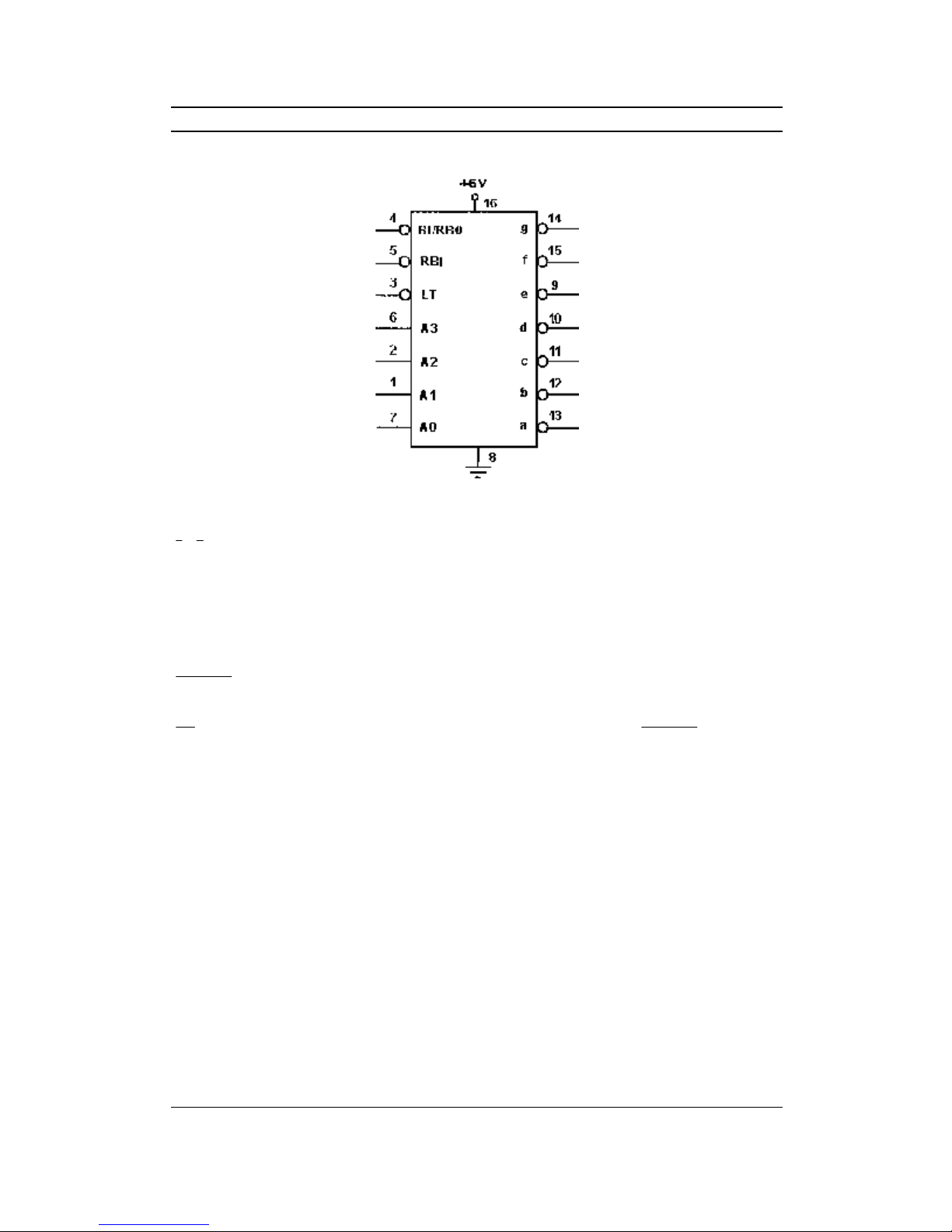
experimentboardhasbeendesignedtostudyBCDto7Segmentdecoderusing
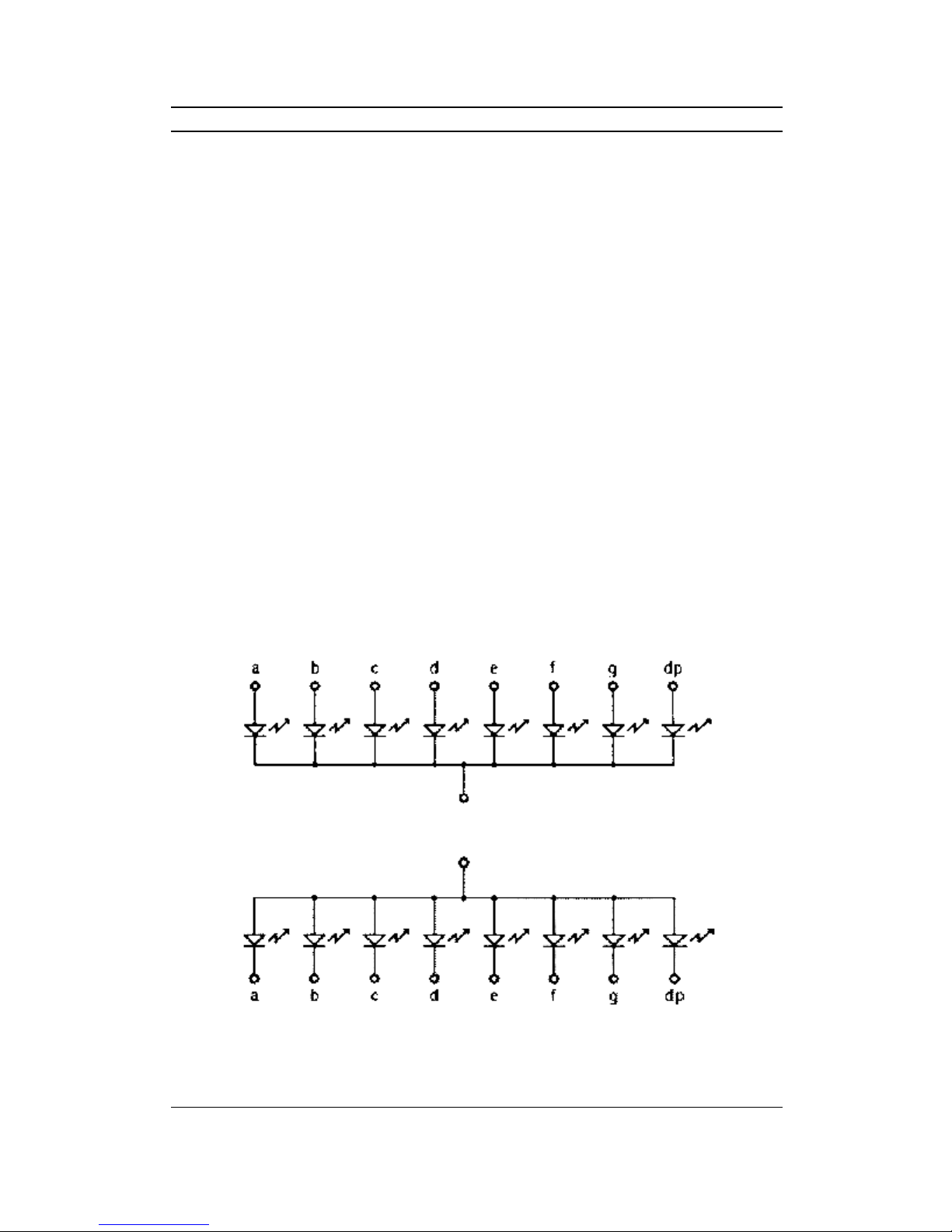
IC74LS47.TheExperimentboardhasinbuiltcommonanodedisplaytostudy
functionalityof74LS47.Itcanbeusedasstand aloneunitwithexternalPower
Supplyorcanbeusedwith ScientechDigitalLabST2611 whichhasbuiltinPower
Supply,pulsegenerator,pulserswitches,8bitsdataswitches,logicprobe,digital
display,8bitsLEDdisplay.
Listofboards:
ModelName
DB01 LogicGates
DB02 UniversalGate-NAND/NOR
DB03 EX-ORGateImplementation
DB04 Demorgan'sTheorem
DB05 EX-ORGateApplication
DB06 CodeConversion(BinarytoGray&GraytoBinary)
DB07 CodeConversion(BCDtoExcess-3code)
DB08 BinaryAdder-Subtractor
DB09 Encoder–Decoder
DB10 Multiplexer–Demultiplexer
DB11 Flip-Flops(R-S, D,J-K,T)
DB12 ShiftRegister(4bitSIPO)
DB13 4BitSynchronousBinaryCounter
DB16 DigitaltoAnalogConverter(R-2Rladder)
DB17 3DigitEventCounter
DB21 FiberOpticDigitalLink
DB22 Analogtodigitalconverter(CounterType)
DB27 DigitaltoAnalogConverter(R-2Rladder)
DB28 MonostableMultivibrator
DB29 CMOSandCrystalOscillator
DB30 Adder/Subtracter(4-Bit/8-Bit)
DB31 Decoder/Demultiplexer
DB32 Modulo-Nprogrammablecounter
DB35 4BIT ShiftRegister
………andmanymore

DB14
ScientechTechnologies Pvt.Ltd.5
Theory
Theavailabilityofalargevarietyofcodesforthesamediscreteelementsof
informationresultsintheuseofdifferentcodesbydifferentdigitalsystem.Itis
sometimesnecessarytousetheoutputofonesystemastheinputtoanother.A
conversioncircuitmustbeinsertedbetweenthetwosystemsifeachusesdifferent
codeforthesameinformation.Thus,acodeconverterisacircuitthatmakesthetwo
systemscompatibleeventhougheachusesadifferentcode.
BCDisanabbreviationforbinary-codeddecimal.Binarycodesfordecimaldigits
requireaminimum offourbits.TheBCDcodeexpresseseachdigitinadecimal
numberbyitsnibbleequivalent. Weightsareassignedtobinarybitsaccording totheir
positions.TheweightsintheBCDcodesare8,4,2,1.Forexample,thebit
assignment0110 canbeinterpretedbytheweightstorepresentthedecimaldigit 6
because0 ×8+1 ×4+1 ×2+0 ×1=6
Asevensegmentdecoder/driverisanICdecoderthatcanbeusedtodriveaseven
segmentindicator.Therearetwotypesofdecoder/drivers,corresponding tocommon
anodeandcommoncathodeindicators.Eachdecoderdriverhas4BCDinputsand7
outputpins(atogsegment).
The74LS47isasevensegmentdecoderforcommonanodedisplay.Therearetwo
importanttypesof7-segmentLEDdisplay.Inacommoncathodedisplay,the
cathodesofalltheLEDsarejoinedtogetherandtheindividualsegmentsare
illuminatedbyHIGHvoltages.Inacommonanodedisplay,theanodesofall the
LEDsarejoinedtogetherandtheindividualsegmentsareilluminatedbyconnecting
toaLowvoltage. Thefigure1, figure2showsthetwodisplays.
CommonCathode Figure1
CommonAnode
Figure2

DB14
ScientechTechnologies Pvt.Ltd.6
ICDescription:
Figure3
A3–A0 :TheseareBCDinputs. A3isMSB.
ga −:Theseareactivelowoutputstodrivecommonanodedisplay.Outputsare
connectedthrough 330 Ωresistorstocommonanodedisplaytolimitthecurrent
throughtheLEDsofdisplay.
BI/RBO(BlankingInput/RippleBlankingOutput) :Whenthispinisatlowlogic
levelallsegmentoutputsareoff regardless ofthelevelofanyotherinput.Itmustbe
athigh logicoropentogetfunctionsfor0000to1111.
RBOBI/RippleBlankingInput :Therippleblanking inputmustbeopenorhigh if
blanking ofadecimalzeroisnotdesired. If itislowitwill blink decimalzero.
LT
(Lamp Test) :Whenblanking input/rippleblankingoutput RBOBI/isopenor
heldhigh andalowisappliedtothisinput,allsegmentoutputsareON.
Note: WhenrippleblankinginputRBIandBCDinputsareatalowlevelwiththe
lamp testinputhigh,allsegmentoutputsgooff andtherippleblanking outputRBO
goestolowlevel.

DB14
ScientechTechnologies Pvt.Ltd.7
Experiment
Objective:
StudyofBCD to7SegmentDecoder usingIC74LS47
EquipmentsNeeded:
1. Digitalboard DB15.
2. DCPowerSupply+5Vfrom externalsource or ST2611DigitalLab.
3. DigitalMultimeteror DigitalLabST2611.
LogicDiagram&TruthTable:
(Logic1=+5V&Logic0= Gnd)
74LS47 LogicDiagram
Figure4

DB14
ScientechTechnologies Pvt.Ltd.8
TruthTable Figure5

DB14
ScientechTechnologies Pvt.Ltd.9
Procedure :
•Connect+5Vandgroundtotheirindicatedpositionon DB15 experimentboard
fromexternalDCPowerSupplyorfrom DCpowerblockof DigitalLab
ST2611.
•ConnectBCDinputstopinsA0,A1,A2A3ofIC74LS47 asshowninlogic
diagramaspertruthtablefrom8bitsdataswitchesof ST2611 orfrom external
source.
•Connect+5Vtopinno.3,4,5.ofIC74LS47
1. SwitchonthePowerSupply.
2. Observedecimaloutputoncommonanodedisplaygivenontheexperiment
board. OutputsofindividualpinscanbeseenonlogicprobeoronLEDdisplay
of DigitalLabST2611 oronmulti-meter.
3. Connectdifferentcombinationofinputsasshownintruthtableandprovetruth
table.
4. Connectlogic0toBI/RBOinput, logic1toRBIandLTinput.
5. Repeatstep5,6andobservetheresults.
6. Connectlogic0toLT input, logic1toRBIandBI/RBOinput.
7. Repeatstep5,6andobservetheresults.
8. Connectlogic0toRBIinput&BCDinputs,logic1toLT&BI/RBOinputand
observetheresults.

DB14
ScientechTechnologies Pvt.Ltd.10
DataSheet
PinoutDiagram(Pin16=Vcc = +5V):
A,B,C,DBCDInputs
RBI
Ripple-Blanking Inputor
LT
Lamp-TestInput
RBO/BI Blanking Inputor
Ripple-Blanking Output
ato gOutputs
NumericalDesignations–ResultantDisplays

DB14
ScientechTechnologies Pvt.Ltd.11
LogicdiagramofIC:
TruthTable

DB14
ScientechTechnologies Pvt.Ltd.12
Warranty
1. Weguaranteetheproductagainstallmanufacturingdefectsfor24monthsfrom
thedateofsalebyusorthroughourdealers.Consumableslikedrycelletc.are
notcoveredunderwarranty.
2. Theguaranteewillbecomevoid,if
a) Theproductisnotoperatedaspertheinstructiongivenintheoperating
manual.
b) Theagreedpaymenttermsandotherconditionsofsalearenotfollowed.
c) Thecustomerresellstheinstrumenttoanotherparty.
d) Anyattemptismadetoserviceandmodifytheinstrument.
3. Thenon-workingoftheproductistobecommunicatedtousimmediatelygiving
full detailsofthecomplaintsanddefectsnoticedspecificallymentioningthe
type,serialnumberoftheproductanddateofpurchaseetc.
4. Therepairworkwillbecarriedout,providedtheproductisdispatchedsecurely
packedandinsured. Thetransportationchargesshallbebornebythecustomer.
ForanyTechnicalProblemPleaseContactusat service@scientech.bz
ListofAccessories
1. PatchCordof1mm. 16”(Red)...............................................................1No.
2. PatchCordof1mm. 16”(Black).............................................................1No.
3. PatchCordsof1mm.16”(Blue)...........................................................6Nos.
4. e-Manual.................................................................................................1No.
Updated18-05-2009
Table of contents
Popular Media Converter manuals by other brands

EVOLUTION MEASUREMENT
EVOLUTION MEASUREMENT EvoScann CANDI ELE-CANDI-CANDI01 Product user guide

Altronix
Altronix NetWaySP4PX installation guide

Kramer
Kramer VP-440H2 quick start guide

Lika
Lika AM58 instruction manual

Pixsys
Pixsys CNV510-PNET-RTU-A user manual

Somogyi Elektronic
Somogyi Elektronic home DTA HIFI instruction manual