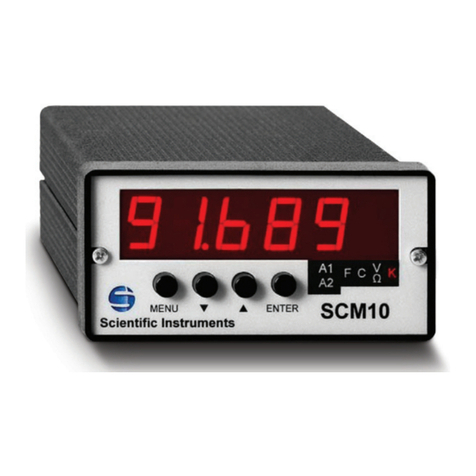
SCIENTIFIC INSTRUMENTS 1900-7 User manual

090-226 Rev. D
Instruction Manual
For
Model 1900-7 & 1901-7
Temperature Indicator
SCIENTIFIC INSTRUMENTS, INC

090-226 Rev. D
TABLE OF CONTENTS
Paragraph Title Page
SECTION I
GENERAL DESCRIPTION
1.1 INTRODUCTION.....................................
.
3
1.2 SPECIFICATIONS...................................
.
3
SECTION II
OPERATIONS
2.1 INPUT/OUTPUT CONNECTIONS ................................
.
4
2.2 OPERATING PROCEDURES ....................................
.
5
2.2.1 ACCESSING SINGLE POINT CALIBRATION MODE
.
.........
.
5
2.2.2 ACCESSING SET POINT MODE (MODEL 1901 ONLY).......
.
5
2.2.3
2.2.4 ACCESSING THE DIAGNOSTIC SUBROUTINE
Default Readouts.................................
.
6
6
2.3 CALIBRATION PROCEDURES ..................................
.
7
2.3.1 ACCESSING EPROM SENSOR CURVE DATA
.
...............
.
7
2.3.2 SETTING OF REFERENCE VOLTAGE
.
....................
.
8
2.4 RS232 OPERATIONAL (MODEL 1901 ONLY)
.
....................
.
8
2.4.1 TEMPERATURE DATA.................................
.
8
2.4.2 SETPOINT DATA....................................
.
9
DRAWINGS
OUTLINE/MOUNTING SPECIFICATIONS
.
......................... A020-098-1

SECTION I
GENERAL DESCRIPTION
1.1 INTRODUCTION
The Model 1900 Microprocessor-Based Temperature Indicator is a 3-digit
instrument designed to operate in conjunction with a ruthenium oxide
sensor to furnish accurate temperature measurement over the range of
1.5 to 273K. Different Models of the ruthenium oxide sensor can be
accommodated. These are:
a. Scientific Instruments, Inc. Model RO-105 (100K)
b. Scientific Instruments, Inc. Model RO-701GE (1K)
c. Scientific Instruments, Inc. Model RO-600 (1K)
Each Model has its own software that has been factory programmed at the time
of order.
Typical voltage vs. temperature data for these specific sensors is stored in
internal EPROMS to match the instrument to the actual sensor being used.
Model 1901 Indicator has the added features of two alarm set points, two
associated alarm relay outputs, and an RS232C interface port. A 0 to 1 or 4
volt DC analog output is also available as an option.
Two front-panel switches enable the user to access a “Single Point
Calibration” (SpCal) function and to set the temperature alarm points. The
SpCal function is a selectable positive or negative offset, which is applied
to the temperature reading.
1.2 SPECIFICATIONS
Sensor Excitation
10 Microamperes Constant Current
Display
3-Digit LED
Temperature Range
1.5 to 300K
Resolution 0.1K from 1.5 to 99.9K
1.0K from 100 to 273K
Accuracy (SpCal)* +/- 0.15K from 1.5 to 80K
+/- 0.15K to +/- 5.0%(80K to 273K)
Power Required 9 VDC @ 500 ma., via a furnished 100-240
VAC/9VDC power converter.
Alarm Setpoints (1901 only) Two, via front panel switches
Alarm Outputs (1901 only) Two SPDT Relays (C, NO, NC)
28 VDC @ 0.25A
RS232 Interface (1901 only) a) Output of Temperature
b) External Setting of Alarm Setpoints
Analog Output (1901 Option) 0 to 1 or 4 volt DC, corresponding to
0 to 273K (2K ohm minimum load)
* Single-Point Calibration (SpCal) is an integrated calibration function
which enables the user to achieve the highest possible system accuracy at the
most important temperature point.
090-226 Rev. D 3

SECTION II
OPERATION
2.1 INPUT/OUTPUT CONNECTIONS
All input and output connections are made at the rear panel of the
instrument:
a) Insert the plug from the power converter into the receptacle at
the extreme right-hand side of the rear panel.
b) Wire the ruthenium oxide sensor to the furnished 5-pin plug
as follows:
Insert this plug into its corresponding receptacle on the rear
panel.
c) Connect the conductors of the RS232 modular IDC cable assembly
(Model 1901 only), to the host computer or terminal as follows:
BLK – Ground GRN – Receive (In)
RED – Transmit (Out) YEL – (No Connection)
Insert the cable assembly receptacle into the RS232 port
located at the extreme left-hand side of the rear panel.
d) The alarm relay outputs are available at the 6-pin terminal
block (Model 1901 only). Pin assignments are as follows:
1 – Relay #1 NO 4 – Relay #2 NO
2 – Relay #1 C 5 – Relay #2 C
3 – Relay #1 NC 6 – Relay #2 NC
e) The analog output is available at the miniature double
banana jack.
090-226 Rev. D 4

2.2 OPERATING PROCEDURES
Several moments after power is applied to the instruments, it will assume
its principal mode of operation which is to display temperature as sensed
by the associated ruthenium oxide sensor. If desired, the operator can:
a) Access the single point calibration mode,
b) change temperature set points (if the instrument is a
Model 1901), and
c) access a special diagnostic subroutine to check
operational readiness of the instrument.
The following paragraphs describe how all of these functions are
accomplished.
2.2.1 Accessing Single Point Calibration Mode
a) Before applying power, press and hold the red “up”
switch. Apply power and release the “up” switch. The
temperature readout will not display the current single
point calibration value.
b) To change this value, immediately press and hold both
t
he
“up” and “down” switches. When the readout begins to
flash, release both switches and press the “up” switch
to increase the calibration setting or the “down” switch
to decrease the setting. When either switch is pressed
once and released, the calibration value changes by one
unit. If either switch is held for one second, the value
changes rapidly.
c) Three seconds after either switch is released, the
calibration value is stored (and displayed for an
additional two seconds), and then temperature is
displayed again.
Accessing Set Point Mode (Model 1901 only)
2.2.2
NOTE: The function of the set points is to control operation
of the two internal alarm relays. If the temperature rises
to, or above the set point established for a given relay
(i.e., set point #1 for relay #1; set point #2 for relay #2),
that relay will energize. If the temperature falls below the
set point, that relay de-energizes.
a) With the instrument in its normal mode of operation (i.e.
displaying temperature), press and release the “up”
switch to display set point #1 or the “down” switch to
display set point #2.
090-226 Rev. D 5

b) To change either set point, press and release the
appropriate switch, then immediately press and hold both
the “up” and “down” switches. When the readout begins to
flash, increase the set point by pressing the “up”
switch or decrease the set point by pressing the “down”
switch. When either switch is pressed and released once,
the set point changes by one unit. If either switch is
held for one second, the value changes rapidly.
c) Three seconds after switch is released, the new set point
is stored (and displayed for an additional two seconds),
and then temperature is displayed again.
2.2.3 Accessing the Diagnostic Subroutine
a) Before applying power, press and hold the “down” switch.
Apply power and release the “down” switch. The
instrument will now enter the diagnostic subroutine and
all eight segments of all readout decades will be
displayed.
b) Press the “down” switch again. The instrument will
display a legend designating which particular ruthenium
oxide curve is being used in the temperature calculation
software. Legends are as follows:
105 – Scientific Instruments, Inc. Model RO-105
701 – Scientific Instruments, Inc. Model RO-701GE
600 - Scientific Instrument's, Inc. Model RO-600
c) Press the “down” switch again. The instrument will
display the version of software in the instrument.
d) Press the “down” switch again. The instrument will
display a “d1” legend and output 0 volts at the analog
output (assuming this option is installed).
e) Press the “down” switch again. The instrument will
display a “d2” legend and output 1 or 4 +/- 0.010 volts
at the analog output.
f) Press the “down” switch once more to return the
instrument to its normal display of temperature.
2.2.4 Default Readouts
a) ‘000’ Indicates an open Sensor.
b) ‘555’ Indicates a possible shorted input or that the
input is outside the range of the instrument.
090-226 Rev. D 6

2.3 CALIBRATION PROCEDURES
CAUTION: THE FOLLOWING PROCEDURE IS PERFORMED BY SCIENTIFIC
INSTRUMENTS, INC. AND IS USUALLY ONLY NECESSARY DURING
INITIAL SET-UP OF THE INDICATOR AT THE TIME OF ORDER. IT
HAS BEEN INCLUDED IN THIS MANUAL FOR INFORMATIONAL PURPOSES
ONLY AND IS NOT NECESSARY FOR ROUTINE USE.
By means of the front panel switches, the operator can access the sensor
curve data stored in the internal EPROMs and select a different curve, if
desired. In addition, through the use of a sensor simulator, the operator
can reset an internal reference voltage. The following paragraphs describe
how these functions are accomplished.
2.3.1 Accessing EPROM Sensor Curve Data
CAUTION: SELECTING THE ALTERNATE SENSOR CURVE REQUIRES BOTH CHANGING
THE SENSOR AND ALSO ADDITIONAL HARDWARE CHANGES WITHIN THE
INDICATOR.
a) Before applying power, press and hold both the “up” and
“down” switches. Apply power. After two seconds, release
both switches, then press and hold the “up” switch. After
two seconds, release the “up” switch and then press and
hold it again for two seconds.
b) When the “up” switch is released, the applicable legend
will be displayed to signify which ruthenium oxide c
u
rve is
being used. The display will flash for two seconds if
neither switch is again pressed.
NOTE: The display will cycle through its programmed
operations (briefly showing reference voltage) until the
legend “CAL” is displayed. At that time, remove power
unless a different curve is to be selected.
c) To select a different curve, press and release either the
“up” or “down” switch while the display is flashing. At
this time, the next sequential legend will be displayed.
Subsequent pressing and releasing of either switch will
cause the instrument to toggle through each curve legend.
When the desired legend is displayed, do not press either
switch; simply wait until the display cycles through its
programmed operations until the legend “CAL” is displayed.
At that time, remove power and the selected curve will be
entered into memory.
WARNING: DO NOT PRESS BOTH SWITCHES WHEN THE “CAL” LEGEND IS
DISPLAYED, OTHERWISE THE INSTRUMENT WILL RECALIBRATE ITSELF AND ITS
TEMPERATURE READINGS WILL NO LONGER BE VALID.
090-226 Rev. D 7

2.3.2 Setting of Reference Voltage
a) Connect a 1 Megohm decade resistance box (General Radio
Model 1433-B, or equivalent) to the sensor input
receptacle in lieu of the 100K ruthenium oxide sensor.
Use a 10K ohm decade resistance box (General Radio Model
1433-W, or equivalent for the 1K sensor.
b) Connect a digital voltmeter (Fluke Model 8840A, or
equivalent) across the decade box terminals.
c) Perform steps “a” and “b” of paragraph 2.3.1.
d) When the legend “CAL” is displayed, set the simulated
sensor input to 1.000 +/- 0.005 volts by means of the 1
Megohm decade box set to 100K ohms. This will calibrate
the 100K Ruthenium Oxide Sensor..
e) Press both the “up” and “down” switches. The instrument
will then accept this new reference voltage (1.2xxx)and
return to the temperature display.
WARNING: PERFORM THIS PROCEDURE ONLY WITH A 1.000 VOLT
INPUT, OTHERWISE INACCURATE TEMPERATURES WILL BE
DISPLAYED.
f) To calibrate the 1K sensor, perform steps A through C
and E using the 10K ohm decade box set at 1K ohms. The
voltage across the box terminals should be .010 +.0001
olts.v
WARNING: PERFORM THIS PROCEDURE ONLY WITH A 10 MV INPUT,
OTHERWISE INACCURATE TEMPERATURES WILL BE DISPLAYED.
2.4 RS232 OPERATIONAL (Model 1901 Only)
a) Connect the conductors of the RS232 modular IDC cable assembly
to the computer as follows:
BLK – Ground GRN – Receive (In)
RED – Transmit (Out) YEL – (No Connection)
Insert the cable assembly receptacle into the RS 232 port
located at the extreme left-hand side of the rear panel.
b) Set the computer to a baud rate of 9600, no parity, 8 data bits
and 1 stop bit.
2.4.1 Temperature Data
a) The Model 1901 will transmit the current temperature
reading to the host computer when a “T” and carriage
return ..<CR>.. are received.
NOTE: The instrument responds to both uppercase and
lowercase letters.
090-226 Rev. D 8

090-226 Rev. D 9
2.4.2 Setpoint Data
a) The Model 1901 will accept a new alarm setpoint value
for the selected relay when the host computer transmits
the following code:
S1, N, <CR>
in which:
S1 indicates that the setpoint is for relay #1.
(S2 is used for relay #2).
N is the temperature setpoint in degrees Kelvin (to
tenths of degree resolution), with the least
significant digit being the tenth’s digit.
<CR> is a carriage return.
EXAMPLE: A setpoint value of 12.3K for relay #2 should be
transmitted as:
S2, 123, <CR>
Since the maximum range of the instrument is 273 Kelvin, the
largest alarm setpoint value that will be interpreted
correctly is 2730.
b) The Model 1901 will transmit the current setpoint value
for the selected relay when the host computer transmits
the follow code:
S1, <CR> or S2, <CR>
as applicable.
This manual suits for next models
1
Table of contents
Other SCIENTIFIC INSTRUMENTS Measuring Instrument manuals
Popular Measuring Instrument manuals by other brands

PCB Piezotronics
PCB Piezotronics ICP 356A15 Installation and operating manual

HKC
HKC APL-3 Series Installation, operation & maintenance manual

KPS
KPS TP5000HY user manual

DeWalt
DeWalt DW0822 instruction manual

Agilent Technologies
Agilent Technologies FieldFox N9912A user guide

VDO
VDO TU00-0752-9207102 installation instructions