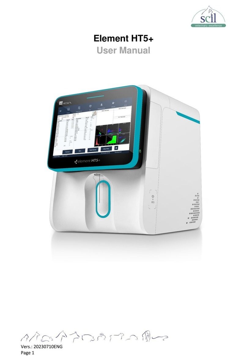
scil element RC User manual

__________________________________________________________________________
Vers. 20210510ENG Page 1
Product Manual
Veterinary Chemistry Analyzer
element RC

__________________________________________________________________________
Vers. 20210510ENG Page 2
Thank you for choosing the element RC fully automated dry biochemistry analyzer.
This manual is configured to provide you with the following instructions:
Features, dimensions, principles of measurement, instructions for use, maintenance,
packaging, storage, and shipping. Please review this instruction manual carefully before use.
To ensure analyzer performance, please note all Warning, Caution and Prompt messages.

__________________________________________________________________________
Vers. 20210510ENG Page 3
TABLE OF CONTENTS
SECTION 1: USING THIS MANUAL..................................................................................... 5
1.1 Scope of Application................................................................................................ 5
1.2 Warning and Safety Symbols .................................................................................. 5
1.3 element RC Analyzer Use....................................................................................... 6
1.4 Compliance with Safety Measures .......................................................................... 7
SECTION 2: INTRODUCTION.............................................................................................. 8
2.1 Analyzer Appearance.............................................................................................. 8
2.2 Basic Introduction.................................................................................................... 8
2.3 Detection Principle .................................................................................................. 9
2.4 Analyzer Structure and Components....................................................................... 9
2.5 Analyzer Function ..................................................................................................10
2.6 Scope of Application...............................................................................................10
2.7 Executive Standard................................................................................................10
2.8 Electromagnetic Compatibility Statement...............................................................11
2.9 Technical Parameters ............................................................................................12
SECTION 3: INSTRUMENT INSTALLATION......................................................................13
3.1 Operating Environment ..........................................................................................13
3.2 Installation..............................................................................................................14
3.2.1 Installing the instrument ..................................................................................14
3.2.2 Insert printer paper..........................................................................................14
3.2.3 External printer................................................................................................14
SECTION 4: COMMON OPERATIONS ...............................................................................15
4.1 Startup ...................................................................................................................15
4.2 Commonly Used Buttons........................................................................................15
4.2.1 Main Screen Buttons.......................................................................................16
4.2.2 Soft keyboard..................................................................................................19
SECTION 5: TESTING AND RESULTS...............................................................................20
5.1 Sample Requirements............................................................................................20

__________________________________________________________________________
Vers. 20210510ENG Page 4
5.1.1 Sample handing..............................................................................................20
5.2 Test Rotor Preparation...........................................................................................20
5.2.1 Reagent rotor storage and disposal.................................................................21
5.2.2 Pipette patient sample.....................................................................................22
5.3 Sample Test...........................................................................................................23
5.4 Test Procedure Precautions...................................................................................25
5.5Print Results...........................................................................................................26
5.5.1 Built-in printer print reports..............................................................................26
SECTION 6: SERVICE AND MAINTENANCE.....................................................................27
6.1 Analyzer Cleaning..................................................................................................27
6.2 Software Upgrade ..................................................................................................27
6.2.1 USB flash drive upgrade .................................................................................28
6.3 Troubleshooting .....................................................................................................29
SECTION 7: PACKING, STORAGE AND TRANSPORTATION..........................................30
7.1 Packing, Storage and Transportation.....................................................................30
SECTION 8: EXPLANATION AND RISK WARNING ON EMC ...........................................31
8.1 Explanation and Risk Warning on EMC..................................................................31
8.1.1 Operating Mode ..............................................................................................32

__________________________________________________________________________
Vers. 20210510ENG Page 5
SECTION 1: USING THIS MANUAL
1.1 Scope of Application
Those qualified to use this analyzer include:
1. Users who received operation training from qualified scil personnel.
2. Users who received the operation training from authorized distributors of scil.
scil reserves the right to revise the instructions and issue software updates.
No individual or organization may reproduce, modify or translate the contents of this manual
without the written consent of scil.
scil has the final interpretation of the contents of this manual.
The illustrations used in this manual are shown as representative samples, which may differ
from the actual products. If there is any difference, the physical product shall prevail.
Be sure to use the analyzer in accordance with the conditions specified in this manual.
Failure to do so may result in failure of analyzer or inaccurate test results.
1.2 Warning and Safety Symbols
WARNING
This information should be followed to avoid potential harm.
Please refer to any symbols in this manual.
CAUTION
All safety precautions and cautions listed in this manual must be
followed.
IMPORTANT
Important prompt message during operation.
BIOHAZARD
Hazardous blood sample and test kits may be present during
operation. Use proper protective gear.
Grounding
Protection
Do not modify the ground.

__________________________________________________________________________
Vers. 20210510ENG Page 6
1.3 element RC Analyzer Use
Follow the instructions below before operation:
❖Please check the analyzer contents and packing list.
❖Please read documents included with the analyzer.
WARNING
The analyzer should be protected from working in humid and corrosive environments. Do not
use flammable or explosive gas around the equipment.
Do not remove covers or other parts that are secured with screws to avoid electrical shock
that may result from exposure to hazardous voltage or injury from moving parts.
Wear protective gloves, lab coat and safety goggles.
It is the user’s responsibility to provide a compatible electromagnetic working environment to
ensure the analyzer will perform as intended.
The analyzer complies with the requirement of equipment emission and immunity in GB/T
18268. The analyzer is designed and tested according to Class A equipment in GB 4824.
Do not use this analyzer near strong radiation sources (such as unshielded FR sources), as
this may interfere with the normal operation of the analyzer.
CAUTION
Avoid installation locations where water may splash on the equipment.
Plug the power cable into an outlet with a grounding receptacle. Electrical shock may occur if
the equipment is not grounded to a protective earth.
Make sure that all cables have been properly connected.
BIOHAZARD
When handling samples (blood) and cleaning or maintaining the analyzer, always follow the
biohazard procedures in accordance with the sample handling rules of your facility.
Use proper protective gear (gloves, lab coat, safety goggles).
Used consumables such as rotors, tips, tubes and cloths used to clean the equipment are
infectious waste. Process this waste in compliance with any applicable local, state or country
regulations.

__________________________________________________________________________
Vers. 20210510ENG Page 7
When discarding the analyzer that may be contaminated with blood samples, follow
applicable regulations for your country and dispose of appropriately.
1.4 Compliance with Safety Measures
For using analyzer safely and efficiently, please observe the following precautions:
1. Avoiding failure of analyzer
The installation environment of the analyzer should meet the requirements of the
installation environment in this manual.
2. Preventing electric shock
Do not open the shell of the analyzer without the authorization of scil and prevent the
introduction of liquids into the analyzer. Please contact scil Technical Support Services
with any questions. Ensure that the power cord is in good condition before use. Do not
use a damaged electric cord to prevent electric shock.
3. Biohazard
Protective gloves should be worn during biochemical testing operations to prevent
biological contamination. If the blood sample is accidently touched, immediately rinse
the contaminated area thoroughly under running water and disinfect.
4. Operating reagent rotor
Reagent beads may contain corrosive substances, follow the instructions strictly in
accordance with the manual. The operator will not contact the reagent beads sealed in
the reagent rotor during normal use unless the reagent rotor fails. If reagent beads are
released, avoid direct contact with reagent rotor and avoid breathing reagent dust.
5. Disposing reagent rotor
Used reagent rotors should be disposed of in accordance with applicable regulations.

__________________________________________________________________________
Vers. 20210510ENG Page 8
SECTION 2: INTRODUCTION
2.1 Analyzer Appearance
2.2 Basic Introduction
Product name:
Fully automated dry chemistry analyzer
Model:
element RC Veterinary Chemistry Analyzer (element RC Analyzer)
Size:
7.87" (200 mm) width x 9.92" (252 mm) depth x 11.77" (299 mm) height
Weight:
10.1 lbs (4.6 kg)
Accessories:
Power cable, Mini-pipette
The element RC Analyzer features simple operation. The analyzer requires Li-Hep whole
blood, Li-Hep plasma or serum sample. Required sample volume is 100μl. Automatic sample
analysis is completed by pipetting patient sample in the test rotor and loading into the
analyzer.
The element RC Analyzer will report results after 12 minutes of analysis. The analysis results
are automatically displayed and printed after the analysis is completed. Furthermore, the
results are transmitted to the practice management software if the instrument is connected.
The Analyzer has four USB ports for connecting external printers, a mouse, keyboard, or
other supported devices.

__________________________________________________________________________
Vers. 20210510ENG Page 9
2.3 Detection Principle
element RC Analyzer is a bio-based analyzer with microcomputer. It is used in conjunction
with the available test rotors to detect the concentration of biochemical substances in the
patient sample, and utilizes the corresponding methods of end- point, rate, two-point method,
and the eight-segment wavelength synchronous detection.
element RC Analyzer uses the principle of absorption spectroscopy. The absorption
spectrum is mainly used for biochemical reaction tests, and its working principle is as follows:
Multiple sets of detection reagents are pre-loaded in the test rotor to form an independent
reaction chamber. The patient sample is added to the test rotor, and then the test rotor is
placed in the analyzer. The system is controlled by the computer processor, and the
biochemical substance in the blood enters the individual reaction chambers and chemically
reacts with the corresponding specific reagent to produce a color change. The absorption
spectrum is used to detect the change, and the calculation is performed by the analyzer
computer to determine the concentration of the biochemical substance present in the patient
blood sample. The turbidimetric method is mainly used for detection with immunochemical
tests, and the working principle is antigen/antibody complex. After binding, an immune
complex is formed, and the turbidity of the complex polymerization occurs within a pre-
defined time frame. When light passes through the solution, it can be absorbed by the
immune complex. The higher the immune complex, the more light is absorbed. The amount
of light absorbed is proportional to the amount of immune complex within a certain range.
The absorbance value is measured by the optical path component transmission, and the
content of the complex is proportional to the absorbance value. Similarly, when the amount
of the antibody is constant, the absorbance value is also proportional to the antigen content,
and the concentration and the content of the immune complex are analyzed to determine the
concentration of the immune complex.
2.4 Analyzer Structure and Components
The analyzer consists of the machine shell, core components, thermostatic temperature
control components, a two- dimensional bar code scanning acquisition component, printer
component, optical path component, LCD capacitive display+ touchpad, operating software
and a power cord.
The analyzer is compact, lightweight and easy to transport.
Analyzer components:
❖An outer plastic shells.
❖A variable speed motor that controls the rotation of the test rotor (machine core
components).
❖A photometer for testing the concentration of substances in a liquid (light path
components).

__________________________________________________________________________
Vers. 20210510ENG Page 10
❖Two microprocessors for controlling instrument and processing test calculations
(Constant temperature, temperature control components, and two-dimensional bar
code scanning acquisition component).
❖A thermal printer for printing results (printer components).
❖7.0-inch color capacitor multi-touch screen (display screen).
❖Multiple selection features related to testing and results processing (operating
software).
2.5 Analyzer Function
❖7.0-inch touch screen, Android operation system with multi-language support.
❖Single channel test, no cross contamination.
❖Advanced optical inspection system, built-in 8 wavelength filters: 340, 405, 450, 505,
546, 600, 630, 850 nm
❖Test methods: End point, rate, fixed time.
❖Sample information storage can be satisfied with customer information storage
demand.
❖Intelligent real-time quality control guaranteed accurate test results.
❖Support for external mouse and keyboard (USB).
❖Built-in thermal printer.
2.6 Scope of Application
The element RC is suitable for biochemical analysis of Li-Hep whole blood, Li-Hep plasma
and serum when used in conjunction with the available test rotors. It is for veterinary
medicine use only.
2.7 Executive Standard
❖The main performance indicators of this product are designed and manufactured in
strict accordance with YY/T 0655–2008 "Dry Chemical Analyzer".
❖The electrical safety of the product complies with the provisions of GB 4793.1–2007
(Safety requirements for electrical equipment for measurement, control and laboratory -
Part 1: General Requirement). The environmental test of the product meets the
requirements of GB/T14710–2009 (Environmental Requirements and Test Methods for
Medical Electrical Equipment).
❖This product meets the special requirements of YY0648–2008 medical equipment
Section 2-101 of (Safety Requirements for Electrical Equipment for Measurement,
Control, and Laboratory Use).
NOTE: Repeating any of the tests in GB 4793.1–2007 on the equipment may damage
equipment and increase the risk of danger!

__________________________________________________________________________
Vers. 20210510ENG Page 11
2.8 Electromagnetic Compatibility Statement
❖This equipment complies with GB/T18268.1–2010 (IEC61326–1:2005, IDT )
"Electromagnetic compatibility requirements for electrical equipment for measurement,
control and laboratory –Part 1: General requirements" and GB/T18268.26–2010
(IEC61326–2–6:2005, IDT ) Electromagnetic compatibility requirements for electrical
equipment for measurement, control and laboratory use Part 26: Particular
requirements for in vitro diagnostic (IVD) medical equipment.
❖The following usage requirements should be strictly observed during use, otherwise
electromagnetic interference may be caused to other equipment or the electromagnetic
interference resistance of the equipment may be reduced or even the basic
performance may be lost.
❖This equipment is designed and tested according to Class A equipment in GB4824. In
a domestic environment, this equipment may cause radio interference and precautions
may be required.
❖Portable and mobile RF communications equipment may affect the description of
medical electrical equipment: Portable and mobile RF communications equipment may
affect the normal operation of this equipment, and portable and mobile RF
communications equipment should be guaranteed to meet certain spatial distances.
See Appendix A, “Recommended Isolation Distances Between Portable and Mobile RF
Communications Equipment and Equipment.”
❖It is recommended to evaluate the electromagnetic environment before the equipment
is used. This equipment should not be used close to or stacked with other equipment.
Except for cables, connecting cables and other accessories sold by the manufacturer
as spare parts for internal components, the components cannot be replaced or repaired
without permission. Otherwise it may cause excessive electromagnetic interference or
disturbance.
❖Do not use this device near strong radiation sources (such as unshielded RF sources)
as this may interfere with proper operation of the device.

__________________________________________________________________________
Vers. 20210510ENG Page 12
2.9 Technical Parameters
Sample type
Lithium heparin whole blood, Lithium heparin plasma and serum
Sample volume
100μl
Bar code
Two-dimensional bar code
Testing time
12 minutes/sample
Testing principle
Absorption spectroscopy, Transmission turbidimetry
Testing method
End point, Rate, Fixed time
Absorbance
0.001 Abs
Cross infection
0
QC & Calibrate
Real time Full-auto finish
Work environment
Temperature: 50ºF–86ºF (10ºC–30ºC) Humidity: 30%-70%
Light source
12 V/20 W, halogen tungsten lamp’s life span is over 2500 hours
Power supply
AC 240 V, 50 Hz
Rated power
120 VA
Optic system
Back dividing light technology, 8 band wavelength synchronization
detection: 340, 405, 450, 505, 546, 600, 630, 850 nm
Display
7 inch 800*480 multi-touch screen, Android system, Multi-language
support
Storage
LAX 500,000 results
Printer
Built-in thermal printer
Connectors
4 USB, one network port
Weight
10.1 lbs. (4.6 kg)

__________________________________________________________________________
Vers. 20210510ENG Page 13
SECTION 3: INSTRUMENT INSTALLATION
3.1 Operating Environment
To ensure optimal performance, the instrument should be installed in accordance with the
following environmental conditions:
❖Elevation not to exceed 6500 feet (2000 m)
❖Temperature: 50ºF–86ºF (10ºC–30ºC)
❖Relative humidity: 30%–70%
❖Barometric pressure: 860 hPa ~1060 hPa.
The analyzer should be installed according the following conditions:
❖Level, stable surface
❖Temperature and humidity control
❖Avoid direct sunlight or excessive heat
❖Avoid sources of vibration or electrical noise and interference (bench top centrifuge)
Do not install the instrument in following conditions:
❖Excessively high humidity, in the presence of corrosive gases, in dusty or unfiltered air,
or near strong electromagnetic interference
❖Without circulating air or adequate ventilation
❖In direct sunlight or near other heat sources
❖Unsteady or tilted work surface
❖Near a centrifuge or other source of vibration or electrical noise
Requirements for power supply:
❖AC 240 V, 50 Hz, rated power: 120 VA
❖The instrument cannot use the same power supply socket with some high-power
equipment including centrifugal, refrigerator, oven, etc.
❖The power supply should earth well and connect the power supply with three-cores
wire; the voltage between the neutral line and earth line < 5 V.

__________________________________________________________________________
Vers. 20210510ENG Page 14
3.2 Installation
3.2.1 Installing the instrument
1. Remove the instrument from shipping carton and place it on a stable, level surface.
2. Inspect for any damage.
3. Connect the power cord to the analyzer.
4. Press the power switch at the back of the instrument, the indicator light will illuminate
below the screen. The system will enter startup and perform a self-test.
3.2.2 Insert printer paper
Spindle
Print Cover
Paper
Print Paper Roll
NOTE: 50 x 57 mm thermal printer paper has been installed during analyzer installation.
Replacing printer paper
1. Open printer cover.
2. Remove printing paper packaging, then place into analyzer with loose end forward.
3. Hold the loose end and route paper under the outlet on the printer door.
4. Close the printer cover.
3.2.3 External printer
This analyzer is compatible with printers using HP PCL3 GUI printer language, HP Deskjet or
other. Refer to your printer’s owner manual for additional information.

__________________________________________________________________________
Vers. 20210510ENG Page 15
SECTION 4: COMMON OPERATIONS
4.1 Startup
Startup screen:
Initialization screen:
4.2 Commonly Used Buttons
The system will automatically enter the interface as shown below in figure 4-1 after analyzer
starts up. Confirm the date and time on the top border is correct.
There are 4 main buttons on the touch
screen interface.
1. Test
2. Reports
3. QC
4. Settings

__________________________________________________________________________
Vers. 20210510ENG Page 16
4.2.1 Main Screen Buttons
1. Test
Run patient sample from this screen.
NOTE: Section 5.3 for further information.
2. Reports
Review prior test results. Select a report
and select to view results.
From the Reports screen, select “ ”
for additional options to the right.
Select Back to exit to Reports screen.

__________________________________________________________________________
Vers. 20210510ENG Page 17
3. QC
Quality control sample lot information and
target ranges can be added in the menu.
4. Settings
Configure the element RC Analyzer:
A. Information settings
B. Parameter settings
C. Print settings
D. Connection settings
E. Log export
F. Others
A. Information settings
Set analyzer date/time and enter clinic or
hospital name.
Select the box for System Time to make
changes.

__________________________________________________________________________
Vers. 20210510ENG Page 18
B. Parameter settings
Change individual assays, such as units,
reference ranges, etc.
NOTE: Do not make changes to
parameters unless advised to do so by a
scil representative.
C. Printing settings
Select the internal printer and turn on
automatic results printing.
D. Connection settings
Select data transmission settings.
NOTE: Do not make changes to
parameters unless advised to do so by a
scil representative.
E. Log export
Export test result data to a USB device
(U:drive). USB device should be FAT32
formatted.

__________________________________________________________________________
Vers. 20210510ENG Page 19
5. Other settings
Do not make changes to parameters
unless advised to do so by a scil
representative.
4.2.2 Soft keyboard
The soft keyboard is a built-in keyboard.
Users can select the field where information
is entered and typed in the window, once
the cursor starts blinking and the soft
keyboard is activated.

__________________________________________________________________________
Vers. 20210510ENG Page 20
SECTION 5: TESTING AND RESULTS
5.1 Sample Requirements
WARNING
Always follow biohazard procedures in accordance with the sample handling rules of your
facility when handling samples (blood).
5.1.1 Sample handing
1. Collect whole blood sample using 22 g (or larger) needle.
2. Gently invert tube several times to ensure proper mixing of sample with lithium heparin.
CAUTION
❖Whole blood must be analyzed or transformed to plasma and serum within 30 minutes
after collection.
❖Do not freeze or shake the sample vigorously, this can hemolyze the sample.
❖If the sample cannot be analyzed immediately after collection, it should be processed
into serum or plasma and stored in sealed sample tube at -20°C. Avoid repeated
freezing-thawing cycles.
❖The patient should be fasted for 12 hours prior to glucose testing.
❖Check the patient sample for clots or hemolysis. Avoid running icteric or lipemic
samples. The analyzer has a built-in centrifugal function - testing will begin after the
anticoagulated whole blood has been spun into plasma. Lithium heparin is the only
recommended anticoagulant, as it will not interfere with on biochemistry analysis.
❖Always wear proper protective gear when handling patient samples.
5.2 Test Rotor Preparation
Test rotors are single use only. The rotors contain diluent at the center and separate tunnels
leading to cuvettes with individual testing reagents to avoid cross contamination.
Table of contents
Other scil Measuring Instrument manuals
Popular Measuring Instrument manuals by other brands

Heal-Tech
Heal-Tech GIpro DS Series Installation and operation manual

FRONIUS
FRONIUS Datamanager 2.0 operating instructions

Audio Control
Audio Control SA-3052A Operation manual

B meters
B meters HYDRODIGIT-S1 operating instructions

Aqua Medic
Aqua Medic pH-Computer Operation manual

Delta OHM
Delta OHM HD2402 manual