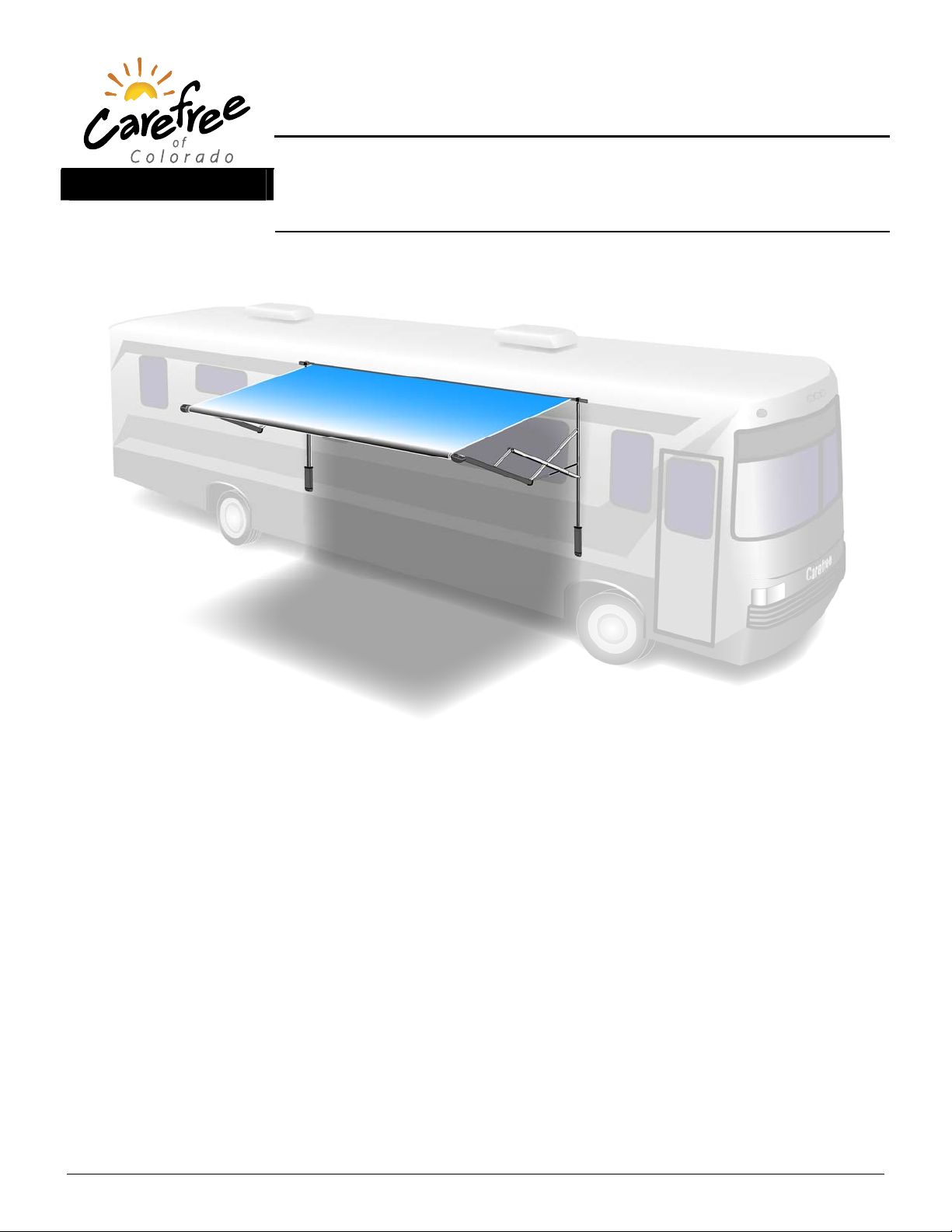
Carefree of Colorado Installation Manual ECLIPSE ARM UPGRADE
052547-101r1 5
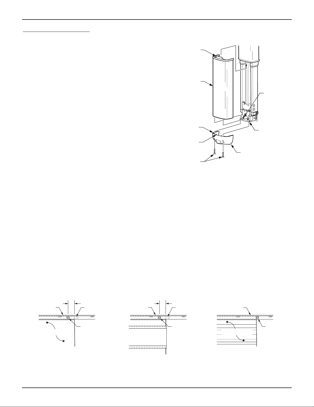
10. (Refer to Detail B) Drill a 5/32” hole at the first mounting hole.
a. If the hole goes into a structural member, attach the motorized arm using a 1/4 x 1 1/2” lag screw.
b. If the hole is through the outer skin only, ream hole out to 7/32” and attach arm with a 3/16” moly rivet.
11. Confirm that the arm is perpendicular to the awning rail, and repeat the previous step for the second
mounting hole (shown in Detail B).
12. Carefully release the ties holding the arm and allow the arm to extend 6"-8" to match the roll bar
position. Tie the arm together in this position (refer to Detail D). Use a soft rag or similar material
under the tie material to protect the finish. CAUTION
THE ARM IS UNDER TENSION FROM THE GAS SHOCK LOCATED IN THE ARM.
For steps 13 & 14 refer to Detail E.
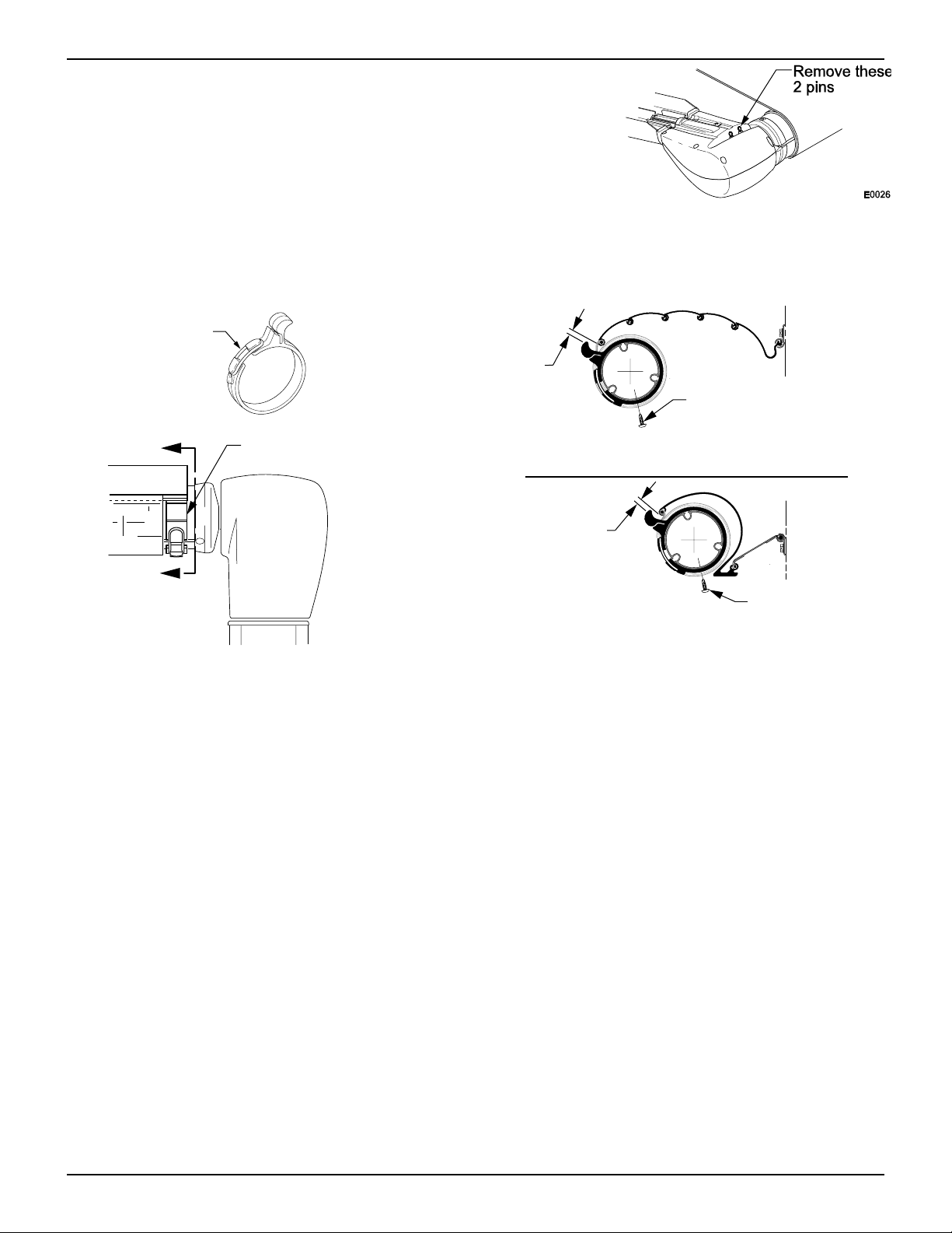
13. For the universal arms:Align the roller assembly with the end cap on the idler arm. Rotate the end cap
until the slot in the cap aligns with the empty slot in the roller assembly, and then press the roller
assembly fully into the cap. The end cap must seat squarely over the end of the roller assembly when
complete. Secure the end cap to the roller assembly using two #10 square-drive screws.
14. For the XL arms: Insert the spring into the roller assy then rotate the end cap until the slot in the cap
aligns with the empty slot in the roller assembly. Finish pressing the roller assembly fully into the cap
and secure using two # 10 square drive screws.
CAUTION
NO PRE-TENSION IS REQUIRED ON THE SPRING.Do not WIND OR TWIST THE SPRING.XL MODEL ONLY.
15. Detach the roll bar from the RH (motor) arm.
16. Using a ladder or similar scaffold, support the roll bar.
17. Remove the screws from the top bracket of the arm, and remove the arm from the coach.
18. Remove the bottom bracket from the coach.
19. Plug and seal the existing holes.
20. Carefully release the ties holding the RH (motorized) arm and allow the arm to extend 6"-8" to match
the idler arm. Tie the arm together in this position (refer to Detail D). Use a soft rag or similar material
under the tie material to protect the finish.
21. Lift and hold the RH motor arm into position and align the roller assembly with the end cap on the idler arm.
Rotate the end cap until the slot in the cap aligns with the empty slot in the roller assembly, and then press the
roller assembly fully into the cap. The end cap must seat squarely over the end of the roller assembly when
complete. Secure the end cap to the roller assembly using two #10 square-drive screws.
22. Butt the top of the rear channel against the awning rail as shown in Detail C. Ensure that the arm is
perpendicular to the awning rail and the coach wall.
NOTE: The centerline of the new arm may not match the centerline of the old arm. Adjust the
horizontal arm position on the coach wall as required.
23. Drill a 5/32” hole at the first mounting hole.
c. If the hole goes into a structural member, attach the motorized arm using a 1/4 x 1 1/2” lag screw.
d. If the hole is through the outer skin only, ream hole out to 7/32” and attach arm with a 3/16” moly rivet.
24. Confirm that the arm is perpendicular to the awning rail, and repeat the previous step for the second
mounting hole (shown in Figure 4).
25. Hold the awning closed and carefully remove the ties on both arms. The awning will open until the
fabric is taut.
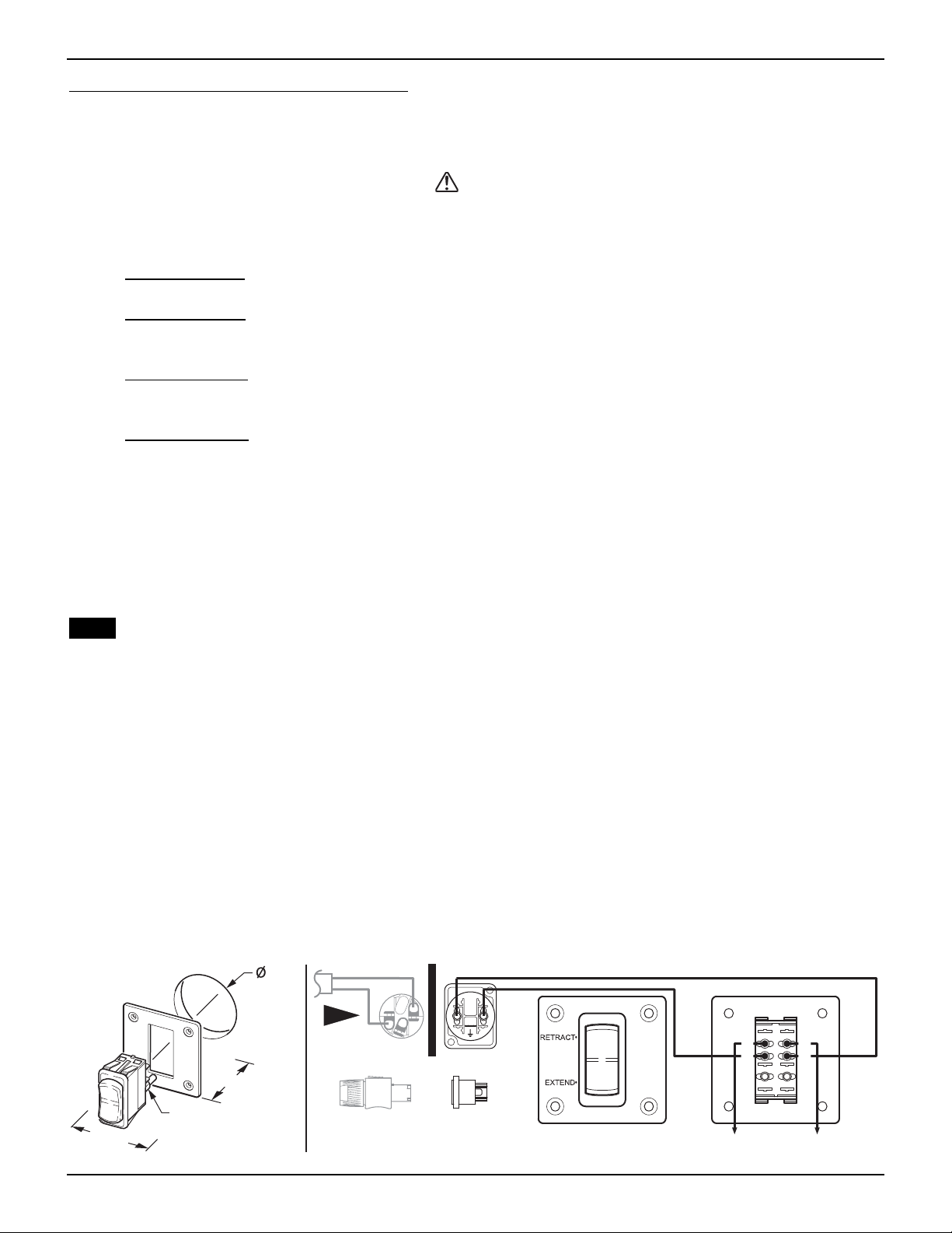
26. (Refer to Detail A) Open the awning about 18” or until the top mounting holes on the arms are visible. To open
26.1 (Refer to Detail F) Use the supplied jumper cables and attach to the emergency terminals located on
the top of the motorized head.
26.2 Connect the other ends of the jumper leads to a 12V source. If the awning does not begin to move,
reverse the leads.
27. Using a 5/32” drill bit, locate and drill the upper mounting holes using the upper bracket as a guide.
28. Using two each 1/4 x 2-1/2” lag screws, attach the top of the arm assemblies to the vehicle.