Scotty eyesite550 User manual

eyesite550
User Manual

Copyright © 2005 SCOTTY Group plc. All rights reserved.
SCOTTY Group of the Americas,
6714 Netherlands Drive, Wilmington, NC 28405, USA
SCOTTY Group plc. (SCOTTY) retains copyright in this manual and associated user
documentation (the Documentation). SCOTTY and its suppliers retain all copyright and other
intellectual property rights in the software embedded in and associated with the product
described in the documentation (the Software). All rights reserved.
By purchasing the product described in the documentation you are granted a limited licence to
use the Software, provided you do not copy, alter or adapt the Software in any way including
decompiling, disassembling or reverse-engineering.
The information provided in the documentation is believed to be accurate and reliable, however,
SCOTTY assumes no responsibility for its use, and reserves the right to revise the
documentation without notice.
SCOTTY, the SCOTTY logo are registered trademarks of SCOTTY Group plc. in the UK, and
are pending application in other countries. All third party trademarks are acknowledged.
4.1.2 May 2005 SD202590A
SCOTTY Web Site
• http://www.scottygroup.com
Product Support
If you have a problem with your eyesite 550:
• First check the Troubleshooting chapter of this manual.
• Check the SCOTTY web site for relevant information.
• If you still have a problem, contact your SCOTTY dealer.
• If this is not possible, contact Customer Services:
•The Americas:
•Europe, Middle East and Africa:
Tel: +43 316 409 426, Email: support.emea@scottygroup.com
•Asia Pacific:
Tel: +63 2 833 7783, Email: support.asiapac@scottygroup.com
You will be asked to supply the following information (found on the base of your
eyesite 550):
Model number: .....................................................
Serial number: .....................................................

IMPORTANT SAFETY INFORMATION
• Do not dismantle the eyesite 550. There are no user serviceable parts inside. Access to the
inside of this unit should only be carried out by approved service personnel.
• Keep the eyesite 550 away from water and other liquids (except when cleaning, as directed
below). If you suspect that liquid has entered the equipment, immediately disconnect the unit
from the network and from the power supply, ensuring first that your hands and the power
supply outlet area are dry. Do not use the eyesite 550 again until it is thoroughly dry.
• Clean the case only with a soft, lint-free cloth, either dry or slightly dampened with water.
Disconnect the power and the telephone cables before using a damp cloth to clean the
eyesite 550.
• Before connecting any equipment that was not supplied with the eyesite 550, check the
specification to ensure compatibility.
• Do not use the eyesite 550 if you suspect a gas leak. Operation of any electrical equipment
can generate sparks which may ignite the gas and cause an explosion.
• Do not let cables trail where they might cause someone to trip or pull the eyesite 550 onto the
floor.
• Use only on a stable surface. The eyesite 550 may be damaged if it falls.
• Do not place any part of this equipment in your mouth.
• Keep the equipment and its packaging out of reach of small children.
• Do not push objects into the ventilation holes.
• Do not block the ventilation slots as this could cause the equipment to overheat and
malfunction. Do not use it on a soft surface such as a bed which might block ventilation slots.
• Do not place the eyesite 550 in direct sunlight. Do not point any external cameras directly at
the sun as this is likely to cause serious damage to the unit.
• The eyesite 550 will not function in the event of a power cut. It should not be relied upon as
the only means of contacting the emergency services.

Connection to the Power Supply
• Never overload power sockets.
• In order to remove power from this product, you must disconnect the power plug from the
power outlet. In order to safely achieve this action, the product must be installed close to the
power outlet and be positioned in such a way that user access to the power plug and socket
connection is not restricted.
• The product must only be used with the provided power supply. This power supply has been
extensively tested for use with the product, use of an alternative power unit may invalidate
any international type approval relating to the product.
• If the power unit, cable or plug becomes damaged, contact the dealer for a suitable
replacement. There are no serviceable parts inside. Disconnect the power source before
attempting to handle a damaged power supply unit or damaged power cable or plug. Any
attempt to open the power unit is likely to expose a potential electric shock hazard.

eyesite 550 Contents
1 Introduction & Getting Started . . . . . . . . . .1
About the eyesite 550 remote video system . . . . . . 2
Getting Started. . . . . . . . . . . . . . . . . . . . . . . . . . . . . 6
Requirements for the eyesite 550 . . . . . . . . . . . . . . 6
Unpacking . . . . . . . . . . . . . . . . . . . . . . . . . . . . . . . . 6
Connecting the Equipment . . . . . . . . . . . . . . . . . . . 7
2 Setting up the eyesite 550. . . . . . . . . . . . .15
Setup Menus . . . . . . . . . . . . . . . . . . . . . . . . . . . . . 15
Setting up the Phone Book . . . . . . . . . . . . . . . . . . 18
Communications Setup . . . . . . . . . . . . . . . . . . . . . 20
Telephone Setup (PSTN). . . . . . . . . . . . . . . . . . . . 21
Network Setup. . . . . . . . . . . . . . . . . . . . . . . . . . . . 22
Configuring the Image Options. . . . . . . . . . . . . . . 30
Configuring the Audio Options. . . . . . . . . . . . . . . 31
Video Presets . . . . . . . . . . . . . . . . . . . . . . . . . . . . . 33
Alarm Triggers and Powered Outputs . . . . . . . . . . 37
Breakout Module. . . . . . . . . . . . . . . . . . . . . . . . . . 46
Pre and Post Event Recording . . . . . . . . . . . . . . . . 47
3 Making a Call . . . . . . . . . . . . . . . . . . . . . . .49
Manual Dialing . . . . . . . . . . . . . . . . . . . . . . . . . . . 49
Speed Dialing . . . . . . . . . . . . . . . . . . . . . . . . . . . . 50
Dialed, Received and Missed Calls lists . . . . . . . . 51
4 Receiving a Call . . . . . . . . . . . . . . . . . . . . .53
Receiving a Call . . . . . . . . . . . . . . . . . . . . . . . . . . 53
Auto Answer . . . . . . . . . . . . . . . . . . . . . . . . . . . . . 54
5 Controlling Cameras During a Call . . . . .55
PiP Control Mode (Picture in Picture) . . . . . . . . . 56
Privacy. . . . . . . . . . . . . . . . . . . . . . . . . . . . . . . . . . 57
Snapshot . . . . . . . . . . . . . . . . . . . . . . . . . . . . . . . . 57
Source (NEAR & FAR). . . . . . . . . . . . . . . . . . . . . 58
Image . . . . . . . . . . . . . . . . . . . . . . . . . . . . . . . . . . . 60

6 Connecting Other Equipment . . . . . . . . . .63
External Connectors . . . . . . . . . . . . . . . . . . . . . . . 64
Connecting a Monitor . . . . . . . . . . . . . . . . . . . . . . 66
Connecting Cameras . . . . . . . . . . . . . . . . . . . . . . . 66
Setting Camera Video Presets . . . . . . . . . . . . . . . . 68
Connecting a Video Recorder (VCR) . . . . . . . . . . 71
Additional Information . . . . . . . . . . . . . . . . . . . . . 71
7 Advanced Options . . . . . . . . . . . . . . . . . . .73
User Options . . . . . . . . . . . . . . . . . . . . . . . . . . . . . 73
Supervisor PIN Mode . . . . . . . . . . . . . . . . . . . . . . 76
Data Ports . . . . . . . . . . . . . . . . . . . . . . . . . . . . . . . 77
Accessing Pre and Post Event Recordings . . . . . . 80
8 Information and Diagnostics . . . . . . . . . .81
The Information Screen. . . . . . . . . . . . . . . . . . . . . 81
Diagnostic Information . . . . . . . . . . . . . . . . . . . . . 82
9 Technical Data . . . . . . . . . . . . . . . . . . . . . .85
Regulatory Notices . . . . . . . . . . . . . . . . . . . . . . . . 89
10 Troubleshooting . . . . . . . . . . . . . . . . . . . . .93
General Maintenance. . . . . . . . . . . . . . . . . . . . . . . 93
Troubleshooting Tips. . . . . . . . . . . . . . . . . . . . . . . 94
Supported Networks and Operation . . . . . . . . . . . 97
Basic Network Configuration . . . . . . . . . . . . . . . . 97
Internet Connectivity. . . . . . . . . . . . . . . . . . . . . . . 98
11 Index . . . . . . . . . . . . . . . . . . . . . . . . . . . . . 111
1
CHAPTER 1 Introduction & Getting Started
This User Manual describes all the features of the eyesite 550 remote video system
and is written both for those who are responsible for installing and configuring it and
those who use it on a day-to-day basis.

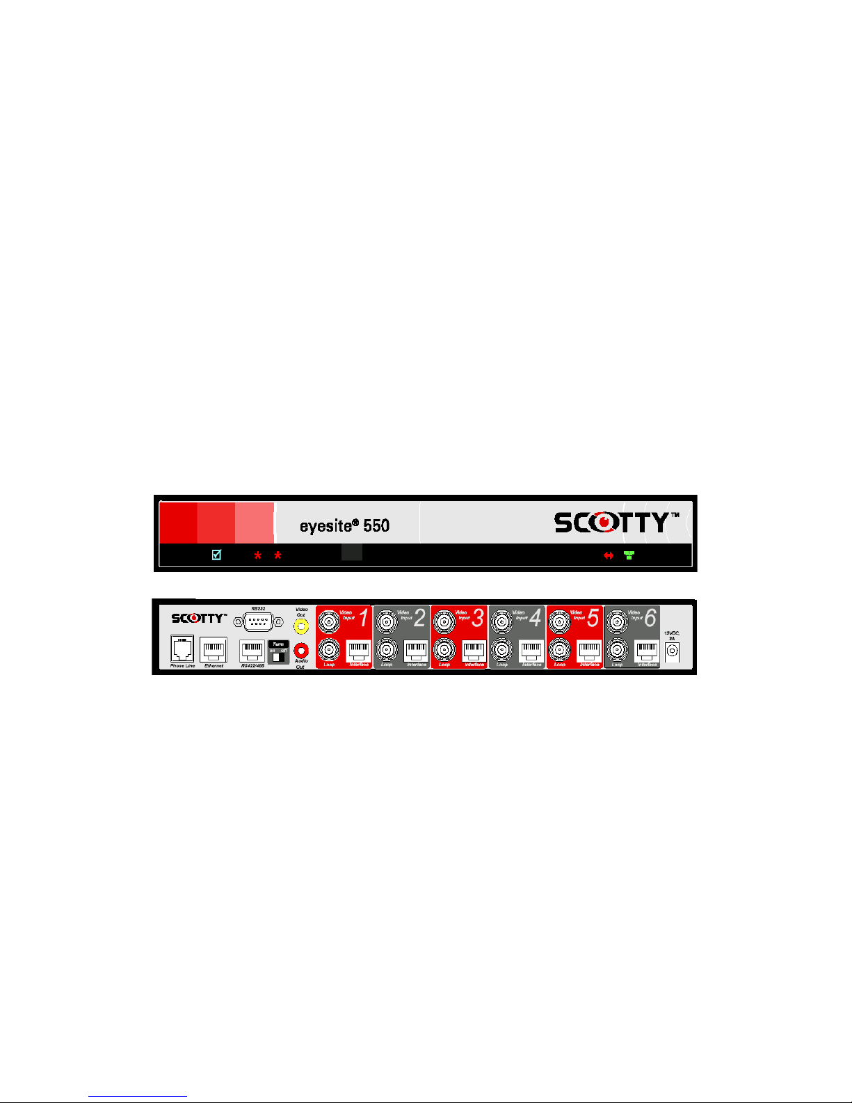
2
About the eyesite 550 remote video system
The eyesite 550 provides real time transmission of remote video over IP and/or
PSTN networks.
The eyesite 550 connects to a standard monitor or TV, providing full-screen video and
flexible video display options such as sizable, moveable picture-in-picture (PIP). The
eyesite 550 unit is lightweight and portable, and it operates over standard IP (Internet
Protocol) networks, allowing remote access to your CCTV system from anywhere in
the world. Secure access is ensured with dual level PIN codes. The infrared remote
control is part of the package - no external telephone or other device is needed to
control the unit. A typical configuration is shown on the next page.
The eyesite 550 offers an array of advanced features including:
• Video and audio transmission at speeds from 32 to 384 kbps
• Support for IP or PSTN transmission and the use of PSTN as a backup to the IP
connection.
• Zone control allowing the cameras to follow movement through a building
• Pre and Post alarm recording
• RS-422/485 interface for long distance connections to PTZ cameras without an
external converter
• Loop through video connectors to allow onward connection of CCTV signals
without an external amplifier.
• Internal web server for configuration, management and monitoring.
• Support for the H.323 protocol allowing integration with 3rd party equipment.
• Support for the SCOTTY StatIX service allowing easy location when using a
dynamic IP address.
Video/Audio Sources
The eyesite 550 offers onboard control for up to six video and audio inputs including
advanced features such as digital pan/tilt/zoom, automatic camera sequencing and
programmable video presets.
Convenient BNC connectors for video inputs make the eyesite 550 compatible with
existing CCTV cameras and devices. Cable-through connections allow the video
feed to continue to another device such as a video recorder. In addition, the RS-422/
485 and RS-232 data channels permit external devices such as PTZ cameras, dome
cameras, multiplexers, matrix switches and DVRs to be controlled through the eyesite
550.

3
Introduction & Getting Started
Using the enclosed eyesite for Windows software on a laptop or PC you can:
• Call into the eyesite 110, 140 or 550 over IP or PSTN phone line connections.
• Receive automatic calls from the eyesite 110, 140 or 550.
• See live video and listen to live audio.
• Take snapshots, save, and send them as JPEG files.
• Control Pan, Tilt, Zoom cameras remotely
• Change camera sources remotely.
By upgrading to eyesite for Windows Pro software you can additionally:
• View multiple remote sites simultaneously
• Record video and audio
• Control and monitor the inputs and outputs on the eyesite 550
• View the pre and post-event recordings on the eyesite 550.
• Send automatic e-mail messages to notify of event occurences.
• View site information such as camera location
• Use the event log to check timing and operator actions

4
Unique technology
eyesite 550 remote video systems offer a range of unique features that improve the
user and administrator experience
Pre-Event Recording
• Retrieve images before the event was triggered. The eyesite 550 stores these
images for you to download.
Auto-Dial on Alarm
• The eyesite 550 can be linked to an alarm panel, sensors, or motion detectors.
During an event the eyesite 550 can automatically connect to a remote
monitoring facility.
6 Independent Zones
• Attach a sensors for each camera, and the eyesite 550 follows activity around
your building without operator intervention.
• Each zone supports 2 way audio. Access can be controlled to a number of doors.
• Each zone supports a controlled output. Unlock a door, set off an alarm, turn on
a light.
• Zones connect using standard category 5 structured cabling- no need to run
dedicated cabling to the zone- just use your existing system.
Web server for Remote Management
• Configure and monitor the status of the eyesite 550 using the built in web server
either locally or remotely.
• Prevent unauthorised users by using the PIN number feature.
Packet Buddy protocol
• Constantly adapts and adjusts to the available bandwidth over the Internet
• Reorders, corrects, and recovers from errors in transmission.
Simplified installation
• The eyesite 550 supports DHCP and PPPoE protocols, allowing automatic
configuration of the core IP information.
• The Packet Buddy Protocol uses a single UDP port to make a video call instead
of the 6+ ports used by an H323 device. This allows outgoing calls to be made
with little or no firewall configuration.

5
Introduction & Getting Started
Reduced infrastructure costs
1. eyesite 550 remote video systems require no dedicated IP video infrastructure
when using SCOTTY’s Packet Buddy protocol.
2. The eyesite 550 also supports the H.323 protocol, so can adapt to future
infrastructure changes, and interoperate with equipment from other vendors.
Enhanced features
A range of features give the user greater flexibility when in a call. These include:
1. Digital zoom
2. Image control (faster/sharper)
3. Local and remote audio and video source selection in call
4. Brightness control
5. Adjustable PiP
6. Freeze frame option
7. PIN authentication for security
8. Make calls over the phone line if the IP network is unavailable or congested

6
Getting Started
Requirements for the eyesite 550
The eyesite 550 unit requires the following:
• Power outlet
• 10 or 100 Base-T LAN (Local Area Network) connection
• And/or standard analog telephone line
• Static IP address or subscription to SCOTTY’s StatIX service.
• TV or monitor on which to view the menus and camera images.
Unpacking
Your shipment should contain the following components:
• eyesite 550 remote video system unit
• Power supply and AC power cord.
• Remote control with batteries.
• Standard network cable (RJ-45)
• PSTN line cable
• AV Cable
• User Manual
• eyesite for Windows CD
Unwrap all the components carefully. If any components are missing, contact your
supplier.
NOTE: Before attempting to make any connections please ensure that you have read
and understood the safety information in the Technical Data chapter.

7
Introduction & Getting Started
Connecting to the Network or Phone Line.
To connect the Phone Line cable
1. Connect one end of the PSTN line cable to the RJ-11 socket labeled ‘Phone
Line’.
2. Connect the other end into the phone line jack on the wall.
To connect the network cable:
1. Connect one end of the network cable into the socket labeled Ethernet at the
rear of the eyesite 550.
2. Connect the other end into your RJ-45 network jack..
Connecting the Power Supply
To connect the power supply:
1. Connect the power supply adapter to the circular power jack labeled
12 VDC, 3A at the rear of your eyesite 550.
2. Connect the AC power cord to the other end of the power supply adapter and
to your wall outlet.
The status light on the front of the eyesite 550 turns from flashing green to
solid green when the system is ready for use.

8
Connecting to a TV
To connect to a TV or Monitor:
1. Connect the supplied AV phono cable to the connector labeled ‘Video Out’
and to the TV’s Auxiliary Video input.
2. Connect the other branch of the supplied AV phono cable to the connector
labeled ‘Audio Out’ and to the TV’s Auxiliary Audio input.
Tip: If your TV or Monitor has stereo inputs, use the left channel input.
Connecting a Pan Tilt Zoom Camera
To connect a PTZ camera:
1. Connect one end of a video cable with BNC connectors to the video input on
the back of the eyesite 550 unit labeled Video Input. Then connect the other
end of the video cable to the PTZ camera.
2. Connect the power adaptor supplied with the camera from a wall outlet to the
power jack on the back of the PTZ camera.
3. Connect the camera control cable to the camera and the serial connector on the
other end to the serial port on the back of the eyesite 550 labeled RS-422/485
(RJ-45) or RS-232 (DB9). You will need to configure the data port in the Data
Options Menu.
Note: When connecting audio signals to the eyesite 550, make sure each audio
source corresponds with the video source from the same camera.

9
Introduction & Getting Started
Using the Remote Control
The Remote Control contains all the keys you need to set up and control the eyesite
550. To use the remote control, point the LED at the Infra-red sensor on the eyesite
550 and press the key you require.
Note: Please insert supplied batteries before use
SNAP
Freezes incoming video
during a call to produce
a high quality snap shot
END
Ends a call
LEFT/RIGHT Arrows
Pan local and remote
cameras or
Choose menu options
MENU
Provides access to
the set up menus
SEL
Allows you to select,
view, and edit video
presets
PRIVACY
Suspends outgoing
audio and video
during a call
START
Used to access speed
dial and manual dial
screens, initiate calls,
and answer calls
UP/DOWN Arrows
Tilt local or remote
cameras or
Navigate menus

10
Set Up Keys
Use the following keys to set up the eyesite 550:
•MENU- Displays the Setup Menu.
•CLEAR- Deletes everything in a highlighted field within a menu.
•ENTER- Saves a selection or entry
•EXIT - Cancels a selection or entry and exits out of the current menu to the
previous menu.
Installing Batteries
Batteries are provided and must be installed before using the remote control. When
the effective range of your remote control becomes noticeably shorter, replace the
batteries with four high quality, alkaline, size AAA batteries. Under typical use, the
batteries will last for more than one year.
Using the Web Server for remote configuration and management.
The eyesite 550 includes a web server allowing local or remote configuration and
management.
Accessing the eyesite 550 web server locally
To access the web server the eyesite 550 first needs to obtain an IP address.
To obtain a valid IP address:
1. Connect a TV to the video out connector of the eyesite 550.
2. Press the Menu button on the remote control and then select 2 for
Communications and 1for Network.
3. Press 1 to select the IP address type and either select Static, entering the IP
address, subnet mask, and default gateway supplied by your network
administrator or DHCP to obtain one automatically.
4. Take a note of this IP address.
5. Browse into the eyesite 550 by typing in http://x.x.x.x into your browser as
shown.
6. The following status page will be displayed

11
Introduction & Getting Started
.
7. Navigate through the web server in a similar manner to normal menu
navigation.

12
Remote Monitoring and Configuration
The eyesite 550 can also be accessed, monitored, and configured remotely. The steps
and recommendations are as follows.
To configure remote web server access:
1. Protect the web server by entering a supervisor PIN as described in Chapter 7-
Advanced Options, User Options
2. Create a port forwarding rule in the firewall.
3. Forward from the public address of your firewall to the private address of the
eyesite 550.
4. Because your firewall probably has its own web configuration page on port 80
you will need to choose an unused port.
5. The forwarding rule in this example would be:
Forward inbound data for 62.173.119.215 (the public IP address of the
firewall) port 3000 to 10.10.2.120 (the private IP address of the unit) port 80
(the standard webserver port number).
6. The data type for this forwarding rule is TCP
7. To browse into the web server remotely type:
8. http://62.173.119.215:3000
9. You will be prompted to enter the PIN number you provided before access is
granted.

15
CHAPTER 2 Setting up the eyesite 550
This chapter explains the menu structure. It then explains how to navigate the menus
that control the cameras and communications.
If you are setting up the eyesite 550 for the first time, you should follow the steps in
this chapter and then go on to the next chapter which explains how to make calls.
Setup Menus
The eyesite 550 unit is configured using the Setup Menu. The Setup Menu provides a
number of options that display further menus and information screens.
To access the Setup Menu:
Press the MENU button on the remote control.

16
Menu Layout
All the menus and information screens have the same format as the Setup Menu:
•Title Bar: At the top of all menus, indicates the menu you are currently viewing.
•Button Bar: At the bottom of all menus, displays information about keys used
for navigating through the menus.
Selecting Menu Options
The menus also have numbered options.
To select an option:
• Press the number key corresponding to the option you require, or
• Use the Up and Down arrow keys to highlight the option.
• Press the SEL or ENTER button to activate an option.
Changing a Setting within a Menu Field
The menus that you access from the Setup Menu contain a number of fields. Some of
these fields have default settings which are displayed for you.
The way in which you navigate through the menus, change settings and save your
changes is the same in each case:
Highlighting a field Use the Up and Down arrow keys on the key pad to move
the cursor to the field you want to change. When the field
is highlighted, you can change its setting.
Changing a setting Use the Left and Right arrow keys to scroll through
pre-defined settings, such as ON and OFF. Display the
setting that you want to use.
Entering numbers Use the number keys to enter numbers such as an
IP address.
Entering letters Also use the number keys to enter text. When you have
highlighted a field that requires text, the “mode” of the
number keys is automatically changed to enter letters.
The 1 to 9 keys represent more than one letter. Press a key
repeatedly to change the letter. When you have displayed
the letter you require, use the Right arrow key to move to
the next space and be able to enter another letter.
Table of contents


