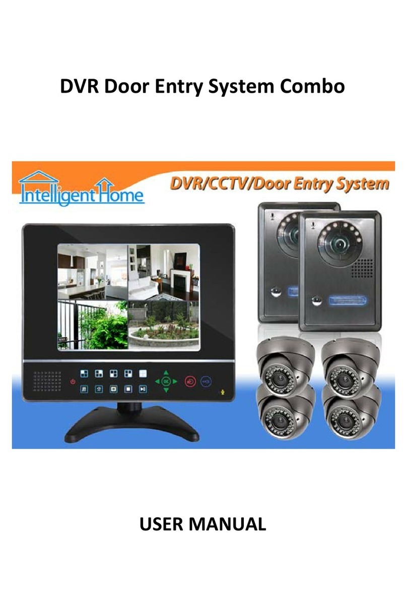
Intelligent Home DT-610 User manual

English
User Manual
2-Wire Video Outdoor Station
DT-ENG-610-V1 190107

-1-
1.Parts and Functions
Camera Lens
Speaker
KEY_CALLLED_KEY
LED_CAM
LED_UNLOCK
Microphone
2.Terminal Descriptions
JP
L1 L2 LK+ LK-
123
ON DIP
456
L1 L2 LK+ LK-
123
ON DIP
456
ON(1)
=
OFF(0)
=
ON
ON
DIP:
Bit 1&2: to set door station address, total 4 door stations
can be supported. Please refer to door station address set-
ting.
Bit 3&4: to set unlock time for door station. Please refer to
unlock time setting.
Bit 5: to set unlock mode for door station(0(OFF):opened/1
(ON):closed).
Bit 6: 0(OFF) > 1(ON), to enter setting mode.
L1,L2:Connect to the bus line, no polarity.
LK+:Lock power(+) output.
LK-:Lock power(-) output, connect to the power(-) input of locks(only when using the door station to
power the locks, if using the external power supply for the locks, the LK- will not be connected).
JP: Lock Control Jumper.

-2-
3.Mounting
1 2
43
1. Installation height for door station usually is 145~160cm.
2. Use screws to x the back panel to the wall after connect the cable correctly.
3. Attach the front panel to the back panel, then use the screw to x it.

-3-
Basic Connection
4.System Wiring and Connections
BUS(IM) BUS(DS)
PC6A
AC~
Doorbell Button
Switch
Code=00, DIP6=on
1 2 3 4 5 6
ON DIP
L2
L1
DIP Switches
L1 L2 LK+ LK-
Electric Lock Connection
LOCK
Jumper position
JP
L1 L2 LK+ LK-
Door Lock Controlled with Internal Power
Note:
1. This mode only supports electromagnetic
locks.
2. Electromagnetic lock of Power-off-to-unlock
type should be used.
3. The door lock is limited to 12V, and holding
current must be less than 250mA.
4. The Unlock Mode Parameter of Monitor
must be set to 1 (by default).

-4-
LOCK
POWER
SUPPLY
Jumper position
JP
L1 L2 LK+ LK-
Door Lock Controlled with Dry Contact
Note:
1. The external power supply must be used according
to the lock.
2. The inside relay contact is restricted to AC or DC
24V/1A.
3. Setup the Unlock Mode of Monitor for different
lock types.
•Power-on-to-unlock type:Unlock Mode=0
(by default)
•Power-off-to-unlock type:Unlock Mode=1
Multi Door Stations Connection
100~240VAC
DBC4A1
A B C D
OFF
ON
Impedance
switch
BUS(IM) BUS(DS)
PC6A
AC~
4# Camera
(Device Address:3)
3# Camera
(Device Address:2)
2# Camera
(Device Address:1)
1# Camera
(Device Address:0)
L1 L2 LK+ LK-L1 L2 LK+ LK-L1 L2 LK+ LK-L1 L2 LK+ LK-

-5-
Basic IN-OUT Wiring Mode
Multi Monitors Connection
Code=14Code=15
(Device Address:0)
BUS(IM) BUS(DS)
PC6A
AC~
100~240VAC
Code=0
NOTE:Here we take DT47MG(the monitor) for example.

-6-
With DBC4A1 Wiring Mode
Code=0
OFF ON
OFF ON
DBC4A1
A B C D
DBC4A1
A B C D
Impedance
switch
Impedance
switch
(Device Address:0)
NOTE:Here we take DT47MG(the monitor) for example.
100~240VAC
BUS(IM) BUS(DS)
PC6A
AC~
Code=3
Code=1
Code=2
Code=12
Code=15
Code=13
Code=14

-7-
Note that this function requires the monitor with sh-eye function to support.
It is available to adjust the display mode for viewing images at a sh-eye door station by using the 5
direction pad button.
5. Pan-tilt & Zoom
Here are some examples:
Touch icon to zoom the center position.
Note: The edge of pantilt image will not be displayed.
Screen of monitor
When an image at a door station is displayed,move
to the desired position by touching
on the screen to view the image in zoom mode.
Press CALL button on outdoor station and the Monitor rings with screen on, or during monitoring state,
the visitors' image will be shown on screen:
In ve direction pad mode, you can zoom in or zoom out the range of monitoring to identify everyone at
the entrance.
When you press any
lattice of the ve direction
pad, the lattice screen
will be enlarged to full
screen.
Press to return to the full screen
mode; Press , , to move, in
order to see individuals up close.

-8-
6. LED status
Different LEDs ON to represent different states.
Please refer to the gure below.
LED_UNLOCK LED_CAM LED_KEY
Monitoring -- Auto(by default) ON(by default)
Calling -- Auto(by default) Flash quickly
Talking -- Auto(by default) Flash slowly
Unlock ON -- --
Upgrad ON -- --
Setup/
Initilization ON -- --
Status
LEDs

-9-
7. Door station address setting
ON(1)
=
OFF(0)
=
ON
ON
Total 2 bits on the DIP switches can be congured.The switches can be modied either before or after installation.
Bit state Descriptions
Default setting, ID = 0(00), set to the rst Door Station.
ID = 1(01), set to the second Door Station.
ID = 2(10), set to the third Door Station.
ID = 3(11), set to the fourth Door Station.
12
ON
1 2
ON
1 2
ON
1 2
ON
8. Unlock time setting
Total 2 bits on the DIP switches can be congured.The switches can be modied either before or after installation.
Bit state Descriptions
Default setting, unlock time is Xs(Default value can be changed).
Set to the unlock time is 3s.
Set to the unlock time is 5s.
Set to the unlock time is 10s.
34
ON
3 4
ON
3 4
ON
3 4
ON

-10-
8. Setup
LED_UNLOCK:ON
LED_KEY:ON
Buzzer No language voice
Press KEY_CALL to switch
language voice prompt mode.
LED_UNLOCK:ON
LED_KEY:ON
Buzzer Language voice 1
Press KEY_CALL to switch
language voice prompt mode.
LED_UNLOCK:ON
LED_KEY:ON
Buzzer Language voice X
Press KEY_CALL to switch
language voice prompt mode.
Press KEY_CALL
...
LED_UNLOCK:ON
LED_KEY:ON
Buzzer Beep+,Beep
Press and hold KEY_CALL
to activate initilization.
LED_UNLOCK:OFF
LED_KEY:ON
After initilization.
Exit out setting mode
automatically.
Set bit 6 to ON or connect power, and within 10s, press and hold KEY_CALL to get into set-
ting state.
Switch Language Voice
Initilization
• If without any operation in 10 seconds, it will exit out setting mode automatically.

-11-
9. Specications
10. Precautions
•Power Supply : DC 24V ;
•Power Consumption: Standby 14mA; Working status 122mA;
• Camera: Color CMOS, 2.0 Mega pixel
• 1/2.7’’ sheye camera,1550wide angle;
•Lock Power supply: 12Vdc, 250mA(Internal Power);
•Mounting: Surface mounting
•Working temperature: -15ºC ~ +55ºC
•Dimension: 160(H)×60(W)×31.5(D)mm
•Please clean the unit with soft cotton cloth, don't use the organic impregnant or chemical clean agent. If
necessary, please use a little pure water or dilute soap water to clean the dust.
•The unit is weather resistant. However do not spray high pressure water on access control keypad directly.
Excessive moisture may cause problems with the unit.
•You must use the right adaptor which is supplied by the manufacture or approved by the manufacture..
•Pay attention to the high voltage inside the products, please refer service only to a trained and qualified
professional.

-12-
The farest monitor
B
A
C
DBC4A1
monitor
monitor
monitor
with two or four monitors
100~240VAC
BUS(IM) BUS(DS)
PC6A
AC~
The maximum distance of the wiring is limited in the DT system. Using different cables may also affect the
maximum distance which the system can reach.
When Monitor quantity < 20
Cable Usage A B C
Twisted cable 2x0.75 mm260 60 30
Twisted cable 2x1 mm280 80 40
When Monitor quantity > 20
Cable Usage A B C
Twisted cable 2x1 mm270 30 20
Twisted cable 2x1.5 mm270 50 30
Note:If the monitor has been specied the distance,refer to the
parameter.
11. Cables Requirements

Note

Note

The design and specications can be modied without notice to the user. Right to interpret
and copyright of this manual are reserved.
DT-ENG-610-V1 190118
Table of contents
Other Intelligent Home Security System manuals