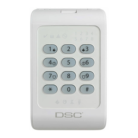
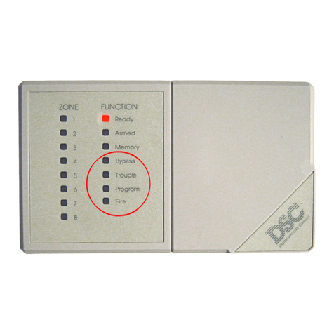
DSC WLS900 User manual

INSTALLATION
MANUAL
Wireless Security System
©1997 Digital Security Controls Ltd.
Printed in Canada 29001429 R3
Security Products
TM
NOTICE:NOTICE:NOTICE:NOTICE:NOTICE:The Industry Canada label identifies certified equipment. This certification means that the equipment meets
certain telecommunications network protective, operational and safety requirements. Industry Canada does not
guarantee the equipment will operate to the user’s satisfaction.
Before installing this equipment, users should ensure that it is permissible to be connected to the facilities of the local
telecommunications company. The equipment must also be installed using an acceptable method of connection. The
customer should be aware that compliance with the above conditions may not prevent degradation of service in some
situations.
Repairs to certified equipment should be made by an authorized Canadian maintenance facility designated by the
supplier. Any repairs or alterations made by the user to this equipment, or equipment malfunctions, may give the
telecommunications company cause to request the user to disconnect the equipment.
Usershouldensurefortheirownprotectionthattheelectricalgroundconnectionsofthepowerutility,telephonelinesand
internal metallic water pipe system, if present, are connected together. This precaution may be particularly important in
rural areas.
CAUTION:CAUTION:CAUTION:CAUTION:CAUTION:Users should not attempt to make such connections themselves, but should contact the appropriate electric
inspection authority, or electrician, as appropriate.
NOTICE:NOTICE:NOTICE:NOTICE:NOTICE:The Ringer Equivalence Number (REN) assigned to each terminal device provides an indication of the
maximum number of terminals allowed to be connected to a telephone interface. The termination on an interface may
consist of any combination of devices subject only to the requirement that the sum of the Ringer Equivalence Number
of all the devices does not exceed 5.
The REN of this unit is 0.1B.The REN of this unit is 0.1B.The REN of this unit is 0.1B.The REN of this unit is 0.1B.The REN of this unit is 0.1B.
AVIS:AVIS:AVIS:AVIS:AVIS:L’étiquette de l’Industrie Canada identifie le matériel homologué. Cette étiquette certifie que le matériel est
conforme à certaines normes de protection, d’exploitation et de sécurité des réseaux de télécommunications. Industrie
Canada n’assure toutefois pas que le matériel fonctionnera à la satisfaction de l’utilisateur.
Avant d’installer ce matériel, l’utilisateur doit s’assurer qu’il est permis de le raccorder aux installations de l’entreprise
localedetélécommunication.Lematérieldoitégalementêtreinstalléensuivantuneméthodeacceptéederaccordement.
L’abonné ne doit pas oublier qu’il est possible que la conformité aux conditions énoncées ci-dessus n’empêchent pas
la dégradation du service dans certaines situations.
Les réparations de matériel homologué doivent être effectuées par un centre d’entretien canadien autorisé désigné par
le fournisseur. La compagnie de télécommunications peut demander à l’utilisateur de débrancher un appareil à la suite
de réparations ou de modifications effectuées par l’utilisateur ou à cause de mauvais fonctionnement.
Pour sa propre protection, l’utilisateur doit s’assurer que tous les fils de mise à la terre de la source d’énergie électrique,
les lignes téléphoniques et les canalisations d’eau métalliques, s’il y en a, sont raccordés ensemble. Cette précaution
est particulièrement importante dans les régions rurales.
AVERTISSEMENT:AVERTISSEMENT:AVERTISSEMENT:AVERTISSEMENT:AVERTISSEMENT:L’utilisateurnedoitpas tenter de faire cesraccordementslui-même; il doitavoir recours à unservice
d’inspection des installations électriques, ou à un électricien, selon le cas.
AVIS:AVIS:
AVIS:AVIS:
AVIS: L’indice d’équivalence de la sonnerie (IES) assigné à chaque dispositif terminal indique le nombre maximal de
terminauxqui peuvent êtreraccordés à une interface.La terminaison d’une interfacetéléphonique peut consisteren une
combinaison de quelques dispositifs, à la seule condition que la somme d’indices d’équivalence de la sonnerie de tous
les dispositifs n’excède pas 5.
L’indice d’équivalence de la sonnerie (IES) de ce produit est 0.1B.L’indice d’équivalence de la sonnerie (IES) de ce produit est 0.1B.L’indice d’équivalence de la sonnerie (IES) de ce produit est 0.1B.L’indice d’équivalence de la sonnerie (IES) de ce produit est 0.1B.L’indice d’équivalence de la sonnerie (IES) de ce produit est 0.1B.
This device complies with RSS-210 of Industry Canada. Operation is subject to the following two conditions: (1) this
device may not cause interference, and (2) this device must accept any interference, including interference that may
cause undesired operation of the device.
Ce dispositif satisfait aux exigences d’Industrie Canada, prescrites dans le document CNR-210. son utilisation est
autorisée seulement aux conditions suivantes: (1) il ne doit pas produire de brouillage et (2) l’utilisateur du dispositif
doit être prêt à accepter tout brouillage radioélectrique reçu, même si ce brouillage est susceptible de compromettre
le fonctionnement du dispositif.
• W A R N I N G •
This manual contains information on limitations regarding product use and function and information
on the limitations as to liability of the manufacturer. The entire manual should be carefully read.

51
iiiii
TABLE OF CONTENTS
INTRODUCTION 1
CHAPTER 1: OVERVIEW 2
1 A: Glossary.............................................................2
1 B: Components ......................................................3
CHAPTER 2: GETTING STARTED 5
2 A: Preparing for Installation ...................................5
2 B: Installing the Controller Battery .........................6
CHAPTER 3: ADDING COMPONENTS 7
3 A: Enrolling the First Keypad.................................7
3 B: Entering the Enrollment Mode...........................8
3 C: Enrolling Sounders............................................9
3 D: Enrolling Detection Devices ...........................10
3 E: Enrolling the Second Keypad .........................11
3 F: Reviewing the List of Enrolled Components ...12
3 G: Removing Components from the System.......13
CHAPTER 4: MODULE PLACEMENT AND TESTING
14
4 A: Locating the Controller and Sounders............14
4 B: Locating System Components........................14
4 C: Entering the Placement Test Mode.................15
4 D: A Note About WLS904 Wireless
Motion Detectors:.............................................16
CHAPTER 5: INSTALLER PROGRAMMING 17
5 A: How to Enter the Installer’s
Programming Mode .........................................17
5 B: Programming Data Entry Sections..................18
5 C: Programming System Option Sections...........19
5 D: Exiting Installer Programming.........................19
CHAPTER 6: ZONE LABELS 20
6 A: Editing Zone Labels ........................................20
6 B: Label Editing Options......................................21
CHAPTER 7: MOUNTINGTHE COMPONENTS 22
7 A: Controller .........................................................22
7 B: Sounder ...........................................................22
7 C: Keypad ............................................................23
7 D: Motion Detector...............................................23
7 E: Universal Transmitter .......................................23
7 F: Smoke Detector ...............................................23
CHAPTER 8: SYSTEM PROGRAMMING SECTIONS24
[00] Binary Programming ........................................24
[01] Zone Definitions ...............................................24
[02] System Times ...................................................26
[03] Installer’s Code ................................................26
[04] Master Code.....................................................26
[05] First System Options ........................................27
1 Quick-Exit Enable / Disable...........................27
2 Auto-Interior Enable / Disable .......................27
3 Door Chime Option Available / Not Available28
4 One-Time Use Code Option..........................28
5 Sounder Shutdown Enable / Disable ............28
6 Second Sounder Operation...........................28
7 Pre-Alert Volume Setting................................28
8 AC Trouble Indication ....................................28
[06] Second System Options ..................................29
1 [F] Key Disable / Enable................................29
2 [P] Key Disable / Enable ...............................29
3 [A] Key Disable / Enable ...............................29
4 [P] Key Audible / Silent..................................29
5 [F] Key Alarm Steady / Pulsed ......................29
6 Bypassing Disable / Enable ..........................29
7 Keypad Lockout Enable / Disable ................29
8 AC Frequency ................................................29
[07] Third System Options.......................................30
1 Entry Delay Off Arming Option ......................30
2 Silent Supervisory Fault .................................30
3 Tamper Faults Transmit Only while Armed....30
4 Interior Zone with Delay.................................30
5 Exit Delay Termination ...................................30
6 Audible Home Mode Arming .........................30
7 - 8 For Future Use ............................................30
CHAPTER 9: COMMUNICATIONS PROGRAMMING
SECTIONS 31
[20] First Monitoring Station Telephone Number....31
[21] Second Monitoring Station Telephone Number31
[22] Account Code ..................................................31
[23] - [38] Notes on Reporting Codes.....................31
[23] Alarm Reporting Codes, Zones 1 to 10...........32
[24] Restoral Reporting Codes, Zones 1 to 10.......32
[25] Closing (Arming) Reporting Codes, Access
Codes 0 to 9.............................................................32
[26] Opening (Disarming) Reporting Codes, Access
Codes 0 to 9.............................................................32
[27] Tamper Reporting Codes, Zones 1 to 10 ........32
[28] Tamper Restoral Reporting Codes,
Zones 1 to 10 ...................................................32
[29] Low Battery Reporting Codes, Zones 1 to 10.33
[30] Low Battery Restoral Reporting Codes,
Zones 1 to 10 ...................................................33
[31] Supervisory Reporting Codes, Zones 1 to 10.33
[32] Supervisory Restoral Reporting Codes,
Zones 1 to 10 ...................................................33
[33] Priority Alarms and Restorals: [F], [A], [P]
and Fire Zone Trouble......................................33
[34] System Trouble Reporting Codes....................34
[35] System Restoral Reporting Codes ..................34
[36] Keypad and Sounder Tamper
Reporting Codes..............................................34
[37] Keypad and Sounder Restoral
Reporting Codes..............................................35
[38] Additional System Reporting Codes. ..............35
[39] Communication Variables ................................36
[40] Test Transmission Time of Day ........................37
[41] Communicator Format Options .......................37
[42] First Communicator Options............................38
1 Communicator Disable / Enable ...................38
2 Dialing Format................................................38
3 Pulse Dialing Ratios.......................................38
4 Transmission Limit Setting .............................38
5 Telephone Line Monitor .................................38
6 Telephone Line Monitor Silent / Audible .......38
7 - 8 For Future Use ...........................................38

52iiii
iiii
ii
[43] Second Communicator Option Code ..............39
1 Restoral Follow Zone .....................................39
2 Restorals on Sounder Time-out.....................39
3 Restorals on Disarming .................................39
4-8For Future Use ...............................................39
CHAPTER 10: DOWNLOADING PROGRAMMING
SECTIONS 40
[70] Downloading Options ......................................40
1 Ring Detect ....................................................40
2 Answering Machine Override........................40
3 Downloading Call-back .................................40
4 User-Initiated Downloading ...........................40
5 Periodic Downloading ...................................40
6-8For Future Use ...............................................40
[71] Downloading Computer Telephone Number...41
[72] Downloading Access Code.............................41
[73] System Identification Code..............................41
[74] Number of Rings Before Answering................41
[75] Installer-Initiated Downloading ........................41
CHAPTER 11: INSTALLERTEST MODES 42
[80] Installer Walk Test Mode ..................................42
[81] Module Placement Test....................................42
[82] Sounder Test ....................................................42
[83] Manual Dialer Test ...........................................42
CHAPTER 12: MISCELLANEOUS PROGRAMMING
SECTIONS 43
[90] Installer Lockout Enable ..................................43
[91] Installer Lockout Disable .................................43
[99] Restore Factory Default Programming ............43
APPENDIX A GUIDELINES FOR LOCATING SMOKE
DETECTORS 44
APPENDIX B CONNECTINGTHE CONTROLLER 45
APPENDIX C ASCII CHARACTER CHART 46
LIMITEDWARRANTY 47
FCC COMPLIANCE STATEMENT inside back cover

1
Introduction
DSC Security Products has made a multimillion dollar investment into the wireless security
market. The Marquis System will be the first of many products to revolutionize the wireless
security industry.
A
short
list of advantages:
• Twelve minute supervisory times versus fifty to sixty minutes
• Six hour supervisory window versus twelve or twenty-four hour
• Standard batteries versus specialized batteries
• High power transmitters versus low power transmitters for better range and propagation
• 3.2" versus 9" ¼ wavelength signal for better propagation
Our new Marquis Supervised Wireless Security System is the culmination of four years of
engineering effort. It is the first Spread Spectrum system to combine true supervision and a
very high level of security into a wireless system.
The Marquis Controller is unique. While it houses the highly sensitive RF receiver and
communicator, it can be mounted almost anywhere, possibly in the bedroom by the bedside
table. Or the Controller can be mounted in a more traditional location near the telephone line
interface. One of the Controller’s unique features is its three built-in communication jacks
which will reduce your installation time.
We felt that in order for wireless to be secure, the Controller had to be separated from the
Keypad. The Marquis Keypad is a full-featured two-way 900MHz wireless device which is used
to program and operate the system from anywhere in or around the premises.
The industry said that it wanted a truly reliable wireless Sounder. The Marquis System’s
wireless Sounder is a 900Mhz transceiver. The Controller and the Sounders are continually
communicating back and forth, confirming everything each step of the way.
Instead of dual spacial diversity, where the receiver has two antennas in the same location,
DSC chose to incorporate true diversity. Each device in the system now has two paths it takes
to the Controller: each transmitter sends directly to the Controller, and to the supervised
Sounder which relays the signal to the Controller, thus providing a true second pathway.
In addition DSC has also been working on other wireless products, such as the LINKSTM series
of Long Range Radio and Cellular Communicators. To date, thousands of LINKSTM products
are installed and in use all over North America. DSC’s commitment to wireless products is
total. DSC has a group of RF engineering specialists, which is something many of our
competitors only wish they could do.
We are confident that your first experience with the Marquis Security System will be positive.
Let us know what you think. Forward your comments to:
DSC Security Products Limited
c/o Product Manager, Wireless Security Systems
1645 Flint Road
Downsview, Ontario
Canada
M3J 2J6

2
Chapter 1: Overview
1 A: Glossary
Several terms are used throughout this manual to refer to parts and operations of the WLS900
System. Read the definitions below to familiarize yourself with the system and its terms.
Access Code The 4-digit code entered by a user to arm or disarm the system. Up to 10
personal Access Codes may be programmed for different users.
Backplate The mounting bracket used to secure each part of the WLS900 System to
the wall.
Component A part of the security system, such as a Motion Detector, Universal
Transmitter, Keypad or other part. Often, the terms “component” and
“module” will be interchangeable.
Enrolling The process of adding a component to the WLS900 System. “Enrolling” a
component tells the system that a component is being added, and what
sort of component it is.
Hexadecimal A number system that uses 0 through 9 to represent the numbers 0
through 9, and the letters A through F to represent the numbers 10
through 15. Hexadecimal numbers are used in some Programming
Sections of the WLS900 System.
HEX An abbreviation for “hexadecimal”. This abbreviation is used in this
manual when referring to hexadecimal numbers or data entry sections.
Module A part of the security system, such as a Motion Detector, Universal
Transmitter, Keypad or other part. Often, the terms “module” and
“component” will be interchangeable.
RF An acronym for “radio frequency”. RF is often used to refer to wireless
radio transmission technology and devices.
Scrolling Using the -YES and -NO Keys to move through messages on the
Keypad display. When the manual indicates to “scroll” to a message,
press the -YES or -NO Key several times until the desired
message is displayed.
Spread Spectrum A specialized radio transmission technology used by the WLS900 System.
Spread Spectrum radio technology is extremely reliable, and is very
resistant to jamming and interference.
Wireless Any system or component that uses radio signals in its operation.
Y / N Abbreviations for “Yes” and “No” used in the Keypad messages. To
answer “yes” to a question on the Keypad display, press -YES. To
answer “no” to a question on the Keypad display, press -NO.
Chapter 1: Overview

3
1 B: Components
Controller
TheController contains thesystem’smain electronics,
RF receiver, communicator and back-up battery. The
Controller is connected to an AC outlet and the
telephone line. The Controller requires:
• AC Adaptor labelled “Controller”
• One 6V 1.2Ah battery
Controller Operating Temperature Range:
• 0°C to 50°C (32°F to 122°F)
Keypad
TheKeypadisusedtooperatethesystemanddisplays
operatinginstructionsandsysteminformationinclear,
easy-to-understand language. The Keypad requires:
• Four AA Batteries
NOTE
:The keypad is shipped with 8 AA batteries.
One set of four batteries should be used for installation
and programming. When you are done installing and
programming the WLS900 system, replace the
batteries in the keypad with the second supplied set.
For more information, see section 3A “Enrolling the
First Keypad”, on page 7.
Keypad Operating Temperature Range:
• 0°C to 50°C (32°F to 122°F)
Sounder
The WLS903 Sounder is used to sound an alert when
an alarm occurs. It is used to indicate that system
functions are being performed. It also performs the
taskofaRFSignalRepeater.TheSounderisconnected
to an AC outlet. The Sounder requires:
• AC Adaptor labelled “Sounder”
• Four AA Batteries
Sounder Operating Temperature Range:
• 0°C to 50°C (32°F to 122°F)
WLS911 Siren
The WLS911 wireless siren is an exceptionally loud
unit with the same functions as the WLS903. It also
has a rechargeable backup battery and an output
for an additional sounding device which will only
operate when the system is in alarm.
Siren Operating Temperature Range:
• 0°C to 50°C (32°F to 122°F)
Motion Detector
The WLS904 Motion Detectors are passive infrared
motion detectors. Each Motion Detector requires
• Four AAA Batteries
Motion Detector Operating Temperature Range:
• 0°C to 50°C (32°F to 122°F)
Chapter 1: Overview
O VERVIEW

4
Universal Transmitter
The WLS905 and WLS907 Universal Transmitters are general purpose
detection devices that may be used as door or window contacts. Universal
Transmittersfeaturetheir own built-in contacts, andthey may also bewired
with external contacts. Each Universal Transmitter requires:
• Three AAA Batteries
Universal Transmitter Operating Temperature Range:
• 0°C to 50°C (32°F to 122°F)
Smoke Detectors
TheWLS906SmokeDetectorsarephotoelectricsmokedetectorsdesigned
for either ceiling or wall mounting. Refer to Appendix A Guidelines for
Locating Smoke Detectors. Each Smoke Detector requires:
• Six AA Batteries
Smoke Detector Operating Temperature Range:
• 0°C to 50°C (32°F to 122°F)
Batteries
The WLS900 System is designed to use Eveready Alkaline Energizer Batteries.
Do not use other brands of batteries with the WLS900 System. Using brands other than the
Eveready Alkaline Energizer will void UL and ULC approvals, and may affect the system’s
operation.
AC Adaptors
The AC adaptors supplied for the Controller and Sounder are not interchangeable. The adaptors are clearly
labelled; ensure the Controller Adaptor is used with the Controller, and the Sounder Adaptor is used with the
Sounder.
WLS905
WLS907
Chapter 1: Overview

5
Chapter 2: Getting Started
Read Chapter One: Overview to familiarize yourself with the WLS900 System, its
components, and the terms used in this manual.
Chapter Two: Getting Started explains how to:
• Prepare the system components for installation
• Reset the system programming to the factory default settings
• Install the battery in the Controller
2 A: Preparing for Installation
Remove all Components from their packaging.
Do not install the batteries at this time!
Remove all Backplates from their Components
Controller
Pull the Controller slightly away from the bottom of the backplate and push up.
Keypad
Pull the Keypad slightly away from the bottom of the backplate and push up.
Sounder
Pull the Sounder slightly away from the bottom of the backplate and push up.
Universal Transmitter
WLS905: Insert a small screwdriver in the slot on the side of the Transmitter.
Gently turn the screwdriver clockwise and pull the module to the left.
Chapter 2: Getting Started
G ETTIN G
STARTED
Universal
Transmitter
Side View
Insert small screwdriver
into slot
Pull module from
mounting plate
WLS907: Insert a small screwdriver in the slot on the side of the
Transmitter. Push the screwdriver in and lift off the cover.
Motion Detector
Push up on the Motion Detector to remove it from its backplate.
Smoke Detector
Turn the Smoke Detector counter clockwise to remove it from its mounting
bracket.
Record the Serial Number found on the back of each component on the
For The Record
page in the Programming Work Sheets booklet.
Ensure all required batteries, AC adaptors, magnets and mounting screws
are on hand.

6
2 B: Installing the Controller Battery
CONTROLLER
BATTERY
CONTROLLER
CIRCUIT
BOARD
CONTROLLER
BATTERY
SHOWN
INSTALLED.
BATTERY WIRES
NOT SHOWN
FOR CLARITY.
Chapter 2: Getting Started
Connect the 6V 1.2Ah battery.
Be sure to connect the RED lead to the RED terminal, and the BLACK lead to the
BLACK terminal. If the connection is made in reverse, the Controller will not be damaged,
but the Controller will not function properly.
Place the battery in the Controller case as shown below.
Replace the back on the Controller case and secure the six screws.
Reconnect the AC Adaptor plug to the AC Adaptor Jack on the Controller.

7
Chapter Three: Adding Components explains how to:
• Add the first Keypad to the system
• Enter the Enrollment Mode
• Add components to the system
• Review the list of components on the system
• Remove components from the system
Chapter 3: Adding Components
ADDING
COM PONENTS
3 A: Enrolling the First Keypad
Two sets of batteries are provided with the keypad. When programming the system, because
of the length of time required, as well as the amount of communication that occurs between the
keypad and controller, the life of the batteries may be reduced. This may cause a low battery
condition to occur before the expected 20 to 24 month battery life period. After programming
the system completely, replace the batteries in the keypad with the second set, to ensure they
are fresh and fully charged.
Install four of the eight supplied AA batteries in the Keypad. Refer to the label
on the back of the Keypad and ensure that the batteries are installed correctly.
When you are done installing and programming theWLS900 system, replace the four batteries in
the keypad with the second supplied set.
Press the [#] Key; this message will be
displayed.
Press the [#] Key; this message will be
displayed.
The Controller Serial Number is printed on
thebackoftheController.EntertheController
Serial Number.
Pressthe -YESKey.WhentheKeypadis
successfully enrolled, it will return to its
inactive state.
Secure the Keypad to its Backplate.
ThismessagewillbedisplayediftheKeypad
is unable to enroll with the Controller. If the
Keypad does not enroll with the Controller,
check the following:
• Ensure that the Controller’s AC Adaptor is properly connected to the
Controller and is plugged in
• Ensure that the Keypad’s batteries are new and properly installed
• Ensure that the Controller serial number was entered correctly
• The Keypad and Controller may be out of range; try enrolling the Keypad
with the Keypad and Controller in the same room.
• Reset the Keypad and the Controller by following the instructions on
performing a hardware reset on page 43.

8
3 B: Entering the Enrollment Mode
Chapter 3: Adding Components
Enter the Installer’s Programming Mode by entering [∗][8][Installer’s Code]
(refer to Chapter 5A, How to Enter the Installer's Programming Mode.)
Press the -Yes Key when this message
is displayed.
When this message is displayed, press the
-YES Key.
The Enrollment Message indicates how
many of each component are enrolled on
the system:
• “0U” represents the number of Universal Transmitters
• “0M” represents the number of Motion Detectors
• “0S” represents the number of Smoke Detectors
• “0A” represents the number of Sounders
• “1K” represents the number of Keypads
In this example, only 1 Keypad has been enrolled on the system. As each
component is enrolled on the system or removed from the system, the number
beside the letter representing those components will be updated.

9
3 C: Enrolling Sounders
Chapter 3: Adding Components
ADDING
COM PONENTS
Enter the Enrollment Mode as described in 3 B: Entering the Enrollment Mode
Do not install batteries in the Sounder until the Sounder is ready to be mounted in its
permanent location.
Plug the Sounder’s AC Adaptor into a wall outlet and plug the Adaptor into
the Sounder AC Jack. A loud beep will sound.
Enter the Sounder’s Serial Number on the
keypad.
Press the -YES Key. The Sounder will
sound two short beeps.
Secure the Sounder to its Backplate. The
Sounder will again sound two short beeps.
As the Sounder is enrolled, the Enrollment
Screen will be updated to indicate how
manySounders are installed on thesystem.
If a second Sounder is required, enroll the Sounder as described in Steps 1
through 5 above. As the second Sounder is enrolled, both Sounders will
beep during the enrollment.
No more then 2 sounders may be enrolled on any one system.

10
3 D: Enrolling Detection Devices
As each detection device is enrolled it is assigned to the first available Zone. That is, the
first device will be assigned to Zone 1, the second will be assigned to Zone 2, and so on. A
maximum of 10 detection devices may be enrolled.
Chapter 3: Adding Components
Enter the Serial Number of the detection
device to be enrolled.
Press the -YES Key. The Sounders will
sound two short beeps.
Install the batteries in the detection device. Refer to the label on the back of
the unit and ensure that the batteries are installed correctly. When the
batteries are installed, the Sounders will beep twice.
Securethedetectiondevicetoitsbackplate.
The Sounders will again sound two short
beeps. As each device is enrolled, the
EnrollmentScreenwillbeupdatedtoindicate
how many components are installed on the
system.
Repeat Steps 1 through 4 above for all remaining detection devices.
• Up to 2 Keypads may be enrolled on the system
• Up to 2 Sounders may be enrolled on the system
• Up to 10 Detection Devices may be enrolled on the system

11
3 E: Enrolling the Second Keypad
Chapter 3: Adding Components
Enter the Serial Number of the Second
Keypad on the
First Keypad.
Press the -YES Key. The Sounders will
sound two short beeps and this message
will be displayed.
Install the batteries in the Second Keypad. Refer to the label on the back of
the Keypad to ensure that the batteries are installed correctly.
On the Second Keypad, press the [#] Key;
this message will be displayed.
On the Second Keypad, press the [#] Key
again; this message will be displayed.
The Controller Serial Number is printed on
thebackoftheController.EntertheController
Serial Number on the
Second Keypad.
On the Second Keypad, press the -YES Key. When the Keypad is
successfully enrolled, it will return to its inactive state and the Sounders will
sound two short beeps.
Secure the Second Keypad to its backplate (the Sounders will not sound
beeps when this is done). As the Keypad is enrolled, the Enrollment Screen
will be updated to indicate how many Keypads are installed on the system.
No more then 2 keypads can be enrolled on any one system.

12
3 F: Reviewing the List of Enrolled Components
In the Installer’s Programming Mode, you can display a list of all the components enrolled on
the system. This function will display all of the detection devices and the zones they are
assigned to, as well as the number of Sounders and Keypads enrolled on the system.
Chapter 3: Adding Components
Entering the Enrollment Mode
(See Section 3B to Enter the Enrollment Mode)
Press the -YES Key when this message
is displayed.
Use the -NO Key to scroll to this
message.Press the -YES Key when this
message is displayed.
Use the -YES Key to scroll through the
list of system components.
Detection Devices will be indicated with
messages similar to this one.
Sounders will be indicated with messages
similar to this one.
Keypads will be indicated with messages
similar to this one.
Whenallcomponentshavebeendisplayed,
this message will be displayed.
To display the Serial Number of a
component, press the [∗] Key while
reviewing Enrolled Components List. When
the[∗]Keyispressed,amessagesimilarto
the one shown here will be displayed for a
few seconds.
*The "ZONE LABEL" can be any discription of up to 16 letters, numbers, spaces or ASCII
characters. See Section 6 for more information.

13
3 G: Removing Components from the System
Follow the procedure below to remove components from the system. You may wish to remove
components for the following reasons:
• The component is no longer required on the system
• A mistake was made in enrolling the component
• The component is not working and requires service
Enter the Enrollment Mode as described in
3 B: Entering the Enrollment Mode
ADDING
COM PONENTS
When this message is displayed, press the
-YES Key.
Usethe -NOKeytoscrolltothismessage.
When this message is displayed, press the
-YES Key.
Usethe -NOKeytoscrollthroughthelist
of components. A message similar to this
will be displayed for each component.
When the desired component is displayed,
press the -YES Key to remove the
component. The Sounders will sound a
single short beep and this message will be
displayed.
Afteracomponentisremoved,thismessage
will be displayed. Press the -YES Key to
remove another component, or press the
-NO Key.
To display the Serial Number of a
component,pressthe[∗]Keywhileviewing
the list of components. When the [∗] Key is
pressed,amessagesimilartotheoneshown
here will be displayed.

14
Chapter Four: Module Placement and Testing explains how to:
• Locate and test system components
• How to enter the Placement Test Mode
Do not permanently mount any of the components until they have been tested!
4 A: Locating the Controller and Sounders
The components of the WLS900 System may be located almost anywhere on the premises.
Only the following guidelines need to be observed:
• Locate the Controller in as central a location as possible
• Locate the Controller in as elevated a location as possible
• If locating the Controller in a basement, mount the Controller as high and as close to
underside of the first floor as possible
• Avoid locations that are subject to extreme temperature variations. Avoid locations that may
be subject to excessive cold (such as an unheated garage), or excessive heat (such as an
attic). Refer to 1 B: Components, for the operating temperature range of each component.
Generally, the WLS900 components are designed to operate within the temperature range
of 0°C to 50°C (32°F to 122°F).
The First Sounder is used to help ensure that the system’s radio transmissions reach the
Controller. The First Sounder should be located within 30 feet (approximately 9 meters) of
the Controller, but no closer than 5 feet (approximately 1.5 meters) to the Controller. A
Second Sounder, if installed, may be located almost anywhere desired.
Chapter 4: Module Placement and Testing
4 B: Locating System Components
Determine the location of the Controller and the First Sounder following the
guidelines noted in 4 A: Locating the Controller and Sounders.
Mount the Controller in the intended location.
Place the system components as near to their intended locations as
possible, but do not permanently install them yet.

15
4 C: Entering the Placement Test Mode
Test the placement of the First Sounder before testing other components!
Carry the Keypad to the location of the component to be tested. The location
of the Keypad will not affect the test, as the Placement Test Mode tests the
component’s ability to communicate with the Controller and Sounder, not the
Keypad.
PLACEM EN T
AND TESTING
Enter the Installer’s Programming Mode as described in 5 A: How to Enter
the Installer’s Programming Mode.
Usethe -NOKeytoscrolltothismessage.
When this message is displayed, press the
-YES Key.
Enter Programming Section [81].
With this message displayed, press the
-YES Key.
Use the -NO Key to scroll to the first
component to be tested.
Pressthe -YES Keytotestthe displayed
component.
Hold the component as close to its intended location as possible.
*The "ZONE LABEL" can be any discription of up to 16 letters, numbers, spaces or ASCII
characters. See Section 6 for more information.
Test each component on the system as described here:
Keypad Press the [#] Key to test the Keypad; the Keypad will display the test result.
Do not remove the Keypad Backplate from the Keypad
during the Placement Test.
Sounder Remove the Sounder from its backplate, wait 5 seconds, then reattach the
Sounder to its backplate. The Keypad will display the test result after the
Sounder is reattached to its backplate.
Door Contact Open and close the contact by moving the magnet or operating the
external device connected to the Door Contact. The Keypad will display
the test result after the zone is restored.
Motion Detectors Remove the Detector from its backplate, wait 5 seconds, then
and Smoke Detectors reattach the Detector to its backplate. The Keypad will display the test
result after the Detector is reattached to its backplate.

16
Press the -YES Key to end the test; this
messagewillbe displayed. To continue testing,
press the -YES Key. To enter the Installer’s
Programming Mode, press the -NO Key.
During the Placement Test, the Sounders will
soundandoneofthemessagesshownherewill
be displayed. When “Location GoodLocation Good
Location GoodLocation Good
Location Good” is
indicated,theSounderwillsoundasinglebeepsinglebeep
singlebeepsinglebeep
singlebeep.
When“Location FairLocation Fair
Location FairLocation Fair
Location Fair”isindicated, the Sounder
will sound two beepstwo beeps
two beepstwo beeps
two beeps. When “LocationLocation
LocationLocation
Location ∗∗
∗∗
∗BADBAD
BADBAD
BAD
∗∗
∗∗
∗” is indicated, the Sounder will sound threethree
threethree
three
beepsbeeps
beepsbeeps
beeps.
Components must be mounted where “Good”
or “Fair” locations are indicated. If “Location ∗
BAD ∗” is indicated, the component should be
relocated. In most cases, it may only be
necessary to move the component a short
distance from its originally intended location.
No sensor should be left in a location that tests
∗∗
∗∗
∗
BAD
∗∗
∗∗
∗
.
The First Sounder must be located where the test indicates “Location Good”.
After moving a component, repeat the test. If “Good” or “Fair” locations are indicated, repeat the Placement Test
at least once to confirm the location. When test results are satisfactory, scroll to the next component and perform
the Placement Test. When satisfactory test results have been received for all components, permanently mount the
components. Refer to “Mounting the Components” in Chapter 7 for mounting instructions.
After completing a Module Placement Test, you
must
arm and disarm the system. Be sure
to allow the exit delay to expire before disarming the system. If you do not arm and disarm
the system, zones may show as open the next time a supervisory transmission is sent
(every 12 minutes).
4 D: A Note About WLS904 Wireless Motion Detectors:
High Traffic Shutdown Mode
To prolong battery life, the motion detector uses a feature called High Traffic Shutdown. When motion is detected,
the device will transmit to the receiver and will then shut down for six minutes. If motion is detected again during
the first six minute shutdown time, the unit will reset the shutdown timer to three minutes. Each time the detector is
tripped during the shutdown time, the timer will be reset to three minutes again. The detector will thus remain in
the shut down mode until it does not detect motion for an entire six minute period.
The High Traffic Shutdown Mode affects testing the motion detector in two ways:
• When performing the module placement testmodule placement test
module placement testmodule placement test
module placement test, the unit must be tampered by removing the unit from the
backplate and replacing it. The placement test cannot be performed by creating motion in front of the device.
• When performing a system testsystem test
system testsystem test
system test, the unit must be left idle for six minutes before testing can be performed.
Once six minutes has passed, create motion in front of the detector to see if the device is both detecting
motion and transmitting to the receiver.
Motion Detector Transmission Delay
A motion detector transmission is always delayed by six seconds. This is necessary to prevent false alarms
caused by a motion sensor transmitting before a delay zone has a chance to report. This six-second delay cannot
be altered or disabled.
Walk Test Mode
The motion detector has a walk test mode which will activate an LED for testing purposes. To put the unit in the
walk test mode, create a tamper by removing the unit from the backplate and replacing it. For the next 90
seconds, the detector’s LED will turn on for three seconds every time motion is detected. During normal operation,
this LED will not turn on.
NOTE:The WalkTest Mode will override the HighTraffic Shutdown Mode.
Chapter 4: Module Placement and Testing
*The "ZONE LABEL" can
be any discription of up
to 16 letters, numbers,
spaces or ASCII
characters. See Section
6 for more information.

17
Chapter Five: Installer Programming explains how to:
• Enter the Installer’s Programming Mode
• Enter data in the programming sections
• How to edit the Zone Labels
5 A: How to Enter the Installer’s Programming Mode
Press the [#] Key; this message will be
displayed.
Chapter 5: Installer Programming
PLACEM EN T
AND TESTING
Enter[∗][8];thismessagewillbedisplayed.
Enter the Installer’s Code. The default
Installer’s Code is [0900]. When the code is
entered, this message will be displayed.
Usethe -NOKeytoscrolltothismessage.
When this message is displayed, press the
-YES Key.
Other manuals for WLS900
1
Table of contents
Other DSC Security System manuals

DSC
DSC LCD5501Z32-433 NA User manual

DSC
DSC Power832 User manual

DSC
DSC POWER 608 User manual

DSC
DSC PowerSeries PC1864 User manual

DSC
DSC Power632 PC1555 User manual

DSC
DSC PC5928 Installation instructions

DSC
DSC Envoy NT9010 User manual

DSC
DSC PowerSeries RFK5500 User manual

DSC
DSC PG9929 User manual

DSC
DSC neo HS2016 User manual

DSC
DSC Power832 PC5015 User manual

DSC
DSC PC1575 User manual

DSC
DSC MAXSYS PC4020 User manual

DSC
DSC PC1000 User manual

DSC
DSC Escort5580 Voice Assisted Security Control User manual

DSC
DSC tyco WP8360 User manual

DSC
DSC Power 864 User manual

DSC
DSC PC1555 - 2 User manual

DSC
DSC PC-LINK9 User manual

DSC
DSC MAXSYS PC4020 User guide