Figure
5B- \
58-2
6C-
I
6C-2
.-,
'-2
'-2
,-.
.-,
.-s
.-,
.-.
8-10
8-11
8-
12
8-1 2
8-\3
8-14
8-\5
8-\6
8 -
17
8-18
FROST
MATTER
LIST
OF
ILLUSTRATI
O:-;S
(ConI)
Modol 28O/SP-14 OC
Control
Circuits
_
Simplified,
Modol 28O/SP-14
Tension
Control
Circui
t _
Simpllfied,
I
nterconnecting
Cabling
, Model 275
El
ec
:
ronlcs
Assembly
Panel,
."
lode
12
75
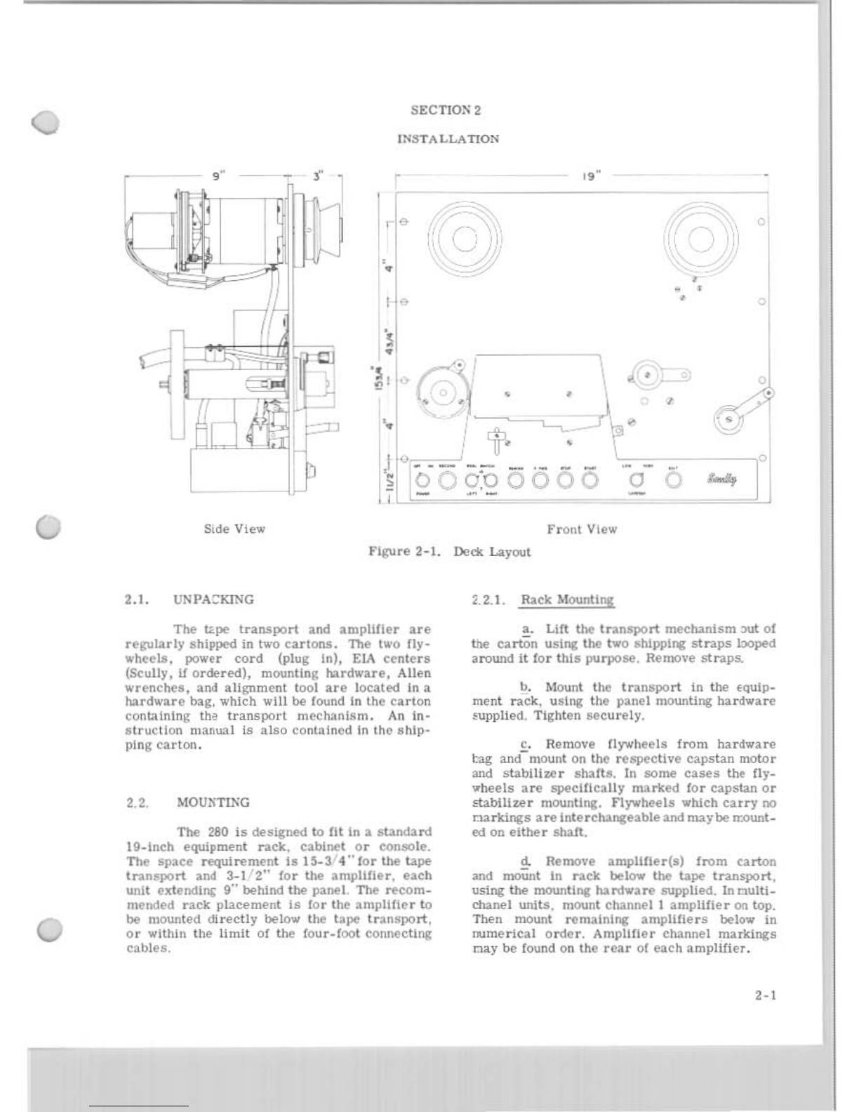
Side View of
Tape
Transport
. . . . .
Magnetic
Head
Assemb
ly, Expl
oded
Vi
ew
.
Tape
Break
Arm
Assembly
...
Auto:n
atic
Front
Shteld
Assembly
. .
Au\
o:natic
Tape
Lifter
Asse
mbly
OC PO"'er Supply,
Schematic
Diagram
Model 280
and
Early
Model
28O/SI'-14,
Power
and
Control
Circuits,
Schematic
Diagram
• . . . . . . . . . . . . . . .
Model 280 wi
th
Motion
Scnsing,
Po,,
'
er
and
Control
Circu!!s,
Schematlc
Dcagram . . . • • • . . . . . . . . . . , , . . . . . . .
Model 28O/SP-14, POwer
and
Contro
l
Circuits,
Schematic
Diagram
Mo,,",
l
28O/SP-14
with Motion
Sensing,
Power
and
Control
Circuits
,
Schematic
Diagram
. . . . . .
..
."...
Model 275
Reproducer,
Po,,-er
and
Con
lro
l
Ci;cuits,
Schematic
Diagram.
Elec
t
ronics
Schematlc
Diagram,
All
V
ersions
of M
odel
21)0
(Sheet J
01
2
Sheets).
.•..
....
.
..
..
. . . . .
Elec
t
ronics
Schematlc
Diagra
m,
All V
ers
i
ons
of
Moool 280 (Sheet 2
01
2She
e
tsl.
. . . . . . , • ,
....
.
..
.
Electronics
Circuit
Cards,
All Mooo is 280,
Parts
location
Diagram
Mode l 275
Electronics
Schematic
Diagram
.
Model 275
Electronics
Clrcu
il
Cards
,
Parts
Location
Diagrams.
Interconnecting
Ca ble
Schematic,
All
\Iodels
280 .
Model 275,
Interconn
ec
ting
Cable
Schematic
..
. .
Remote
Control
Unit,
Cat.
No, 504210100 -01.
Schematic
Diagram
(for Motion Sensi
ng
M
odels
280 a nd
280/SP-14)
.
""'-
6B-3
68-4
6C-2
6C-3
8-5/8_6
8-1/8-8
8-9/8-10
8-11/8_12
8-13/8-14
8-15/8-15
8-17(8-18
8-19/8-20
8-21/8·22
8-23/8-24
8-25
8-25
8-26
8-27
8-28
8-29/8-30
8-31/8-32
8-33/8-34
Iii