Amit RRE2-A/101 User manual

rre2-a101_g_en_101
RRE2-A/101
Analogue inputs unit
With Ethernet interface
Operation manual
Version 1.01

RRE2-A/101
rre2-a101_g_en_101 2/27
AMiT, spol. s r.o. does not provide any warranty concerning the contents of this
publication and reserves the right to change the documentation without
obligation to inform anyone or any authority about it.
This document can be copied and redistributed under following conditions:
1. The whole text (all pages) must be copied without any changes.
2. All redistributed copies must retain the AMiT, spol. s r.o. copyright notice
and any other notices contained in the documentation.
3. This document must not be distributed for purpose of making profit.
The names of products and companies used herein can be trademarks or
registered trademarks of their respective owners.
AMiT is a registered trademark.
Copyright (c) 2014, AMiT, spol. s r. o.
Producer: AMiT, spol. s r. o.
Naskové 3/1100, 150 00 Praha
www.amitomation.com

RRE2-A/101
3/27 rre2-a101_g_en_101
Contents History of revisions.........................................................................................4
Related documentation...................................................................................4
1. Introduction..........................................................................................5
2. Technical parameters..........................................................................6
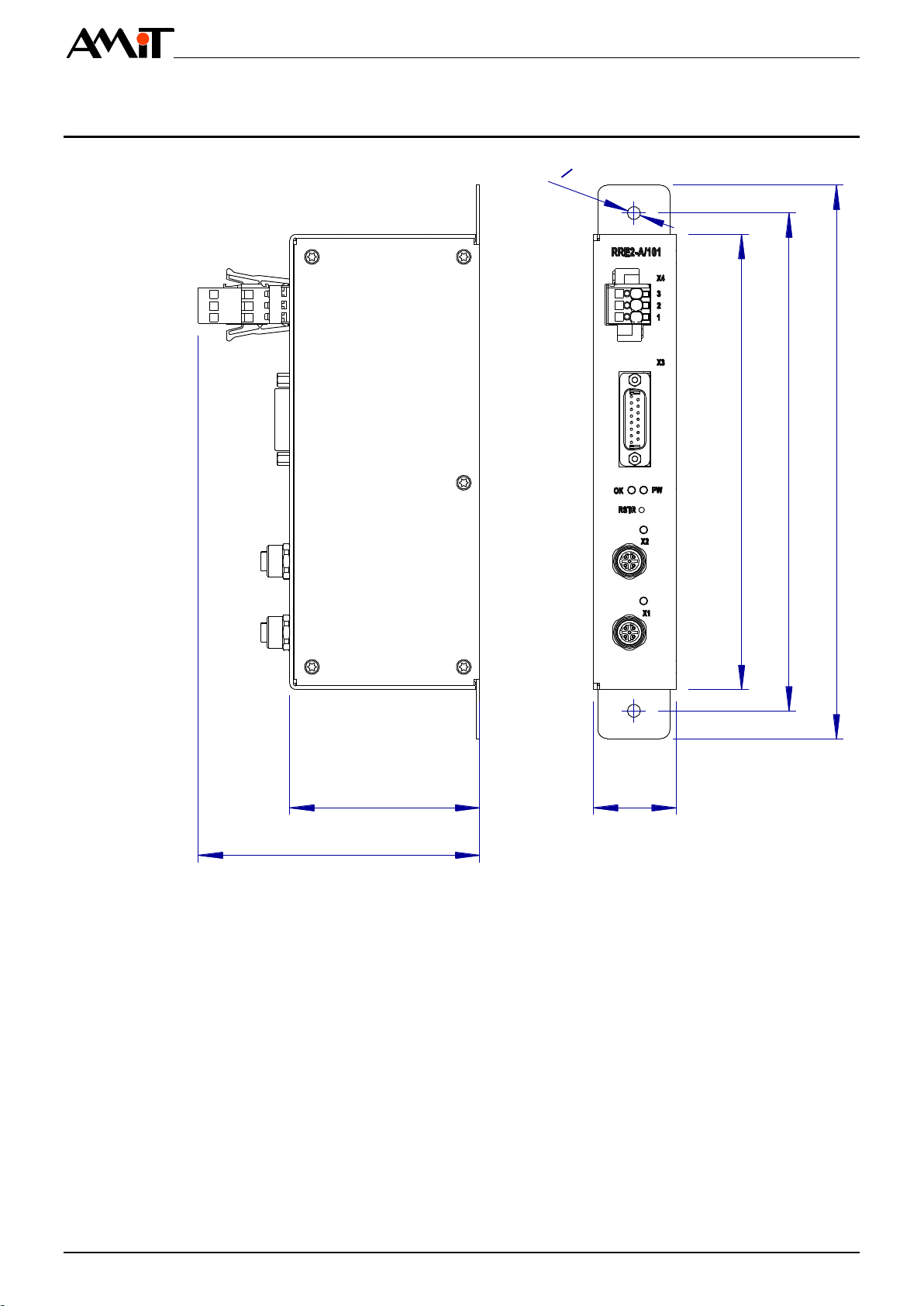
2.1. Dimensions.....................................................................................................8
2.2. Recommended drawing symbol .....................................................................9
3. Unit marking.......................................................................................10
3.1. Producer type label.......................................................................................11
4. Conformity assessment ....................................................................12
4.1. Other tests....................................................................................................12
5. Elements on the front panel..............................................................14
6. Power supply......................................................................................15
7. Inputs ..................................................................................................16
8. Ethernet...............................................................................................17
9. System LEDs......................................................................................18
10. Configuration .....................................................................................19
10.1. Factory setting..............................................................................................19
11. Mounting.............................................................................................20
11.1. Mounting instructions....................................................................................20
11.2. Mounting apertures.......................................................................................20
11.3. Installation rules............................................................................................21
12. Factory settings .................................................................................22
12.1. Software equipment......................................................................................22
13. Ordering information and completion .............................................23
13.1. Completion ...................................................................................................23
14.Packing ...............................................................................................24
15. Storing.................................................................................................25
16. Maintenance .......................................................................................26
17. Waste disposal...................................................................................27

RRE2-A/101
rre2-a101_g_en_101 4/27
History of revisions
Document name: rre2-a101_g_en_101.pdf
Revision
Date
Author of change
Changes
100
30. 3. 2015
Šach J.
New document
101
16. 12. 2016
Šach J.
Added required chapters Packing, Storing, Product marking
Related documentation
1. Application Note AP0037 –Principles of using Ethernet network
file: ap0037_en_xx.pdf
2. Application Note AP0051 –Ethernet network cabling on rolling stock
file: ap0051_en_xx.pdf

RRE2-A/101
5/27 rre2-a101_g_en_101
1. Introduction
RRE2-A/101 is a remote inputs unit with Ethernet interface.
Device is supplied from factory only with loader. Before first use must be loaded
an user application into device.
▪4 × mutually galvanically isolated digital input
▪2 × Ethernet, connector M12
▪Power supply 24 V DC
▪Mounting on base plate
▪Design according to EN 50155:2007
Basic features

RRE2-A/101
rre2-a101_g_en_101 6/27
2. Technical parameters
Number of inputs
4
Voltage range
0 V DC to 10 V DC
Frequency range
0 Hz to 10 kHz
Galvanic isolation
Yes
Galvanic isolation strength
1000 V AC /1 minute *)
Max input current
5 mA at 10 V DC
Reverse polarity protection
No
Max. level of input signal
34 V DC
Input state indication
NO
Connection point
D-SUB 15A connector
Number of lines
2
Data transmission rate
10 / 100 Mbps
Galvanic isolation
Yes *)
Galvanic isolation strength
1000 V AC /1 minute *)
Connection point
M12 connector according to IEC 61375-3-4:1
Recommended cabling
STP CAT5
Maximum segment length
100 m
*) Isolation must not be used for dangerous voltage separation.
Nominal power supply voltage
24 V DC
Power supply voltage range
16.8 V DC to 33.6 V DC
Power consumption
Max. 0.25 at 24 V DC
Peak inrush current
200 A, for time shorter than 200 µs
Connection point
WAGO 769-663/003-000
Mechanical design
Formed metal, thickness 1.5 mm
Colour
Light grey, RAL 7035
Mounting
On the panel, 2 × ϕ 5.5 mm
Ingress protection rate
IP20
Weight–netto
–brutto
0.75 kg ±5 %
0.9 kg ±5 %
Dimensions (w × h × d)
(35 × 234 × 124) mm
Package dimensions (w × h × d)
(67 × 270 × 170) mm
Unit overall mass of plastics
72.6 g ±5 %
Included mass of self-
extinguishing plastics
72.6 g ±5 %
Device does not contain
PUR, PVC, Asbestos
Device conforms
2011/65/EU (ROHS)
1907/2006EU (REACH)
Operating temperature range
-40 °C to + 70 °C
Storage temperature range
-40 °C to + 70 °C
Maximum ambient humidity
< 95 % non-condensing
Expected MTBF
> 500 000 h
Expected lifetime
15 years
Analogue
inputs
Ethernet
Power supply
Mechanics
Dangerous
materials
Temperatures
Others

RRE2-A/101
7/27 rre2-a101_g_en_101
Device is supplied with loader, which enables software downloading via Ethernet line.
No
Equipment is intended to operate up to 1 400 m above the sea level.
Equipment is designed to meet the Temperature Class TX.
According to EN 61373:2010 standard, the equipment is classified in terms of
vibrations into Category 1, Class B (mounting to vehicle body).
Permissible supplying voltage drop-out duration: max. 10 ms (Class S2 according to
Chapter 3.1.1.2 of EN 50155 ed. 3
For supply voltage switching are permissible conditions of C1 and C2 Class.
The device meets the SWSIL0 classification according to EN 50128:2011 Railway
applications - Communications, signalling and processing systems - Software for
railway control and protection systems.
The equipment meets the SIL0 classification according to EN 50129:2003 Railway
applications - Communication, signalling and processing systems - Safety-related
electronic systems for signalling.
Software
equipment
Components
with reduced
lifetime
Claims of
EN
50155:2007
Safety
classification

RRE2-A/101
rre2-a101_g_en_101 8/27
2.1. Dimensions
35
192
210
o 5,5
85
124
234
Fig. 1 - Unit dimensions RRE2-A/101

RRE2-A/101
9/27 rre2-a101_g_en_101
2.2. Recommended drawing symbol
Following drawing symbol is recommended for the RRE2-A/101 unit. Only part
of it will be visible in following examples.
PWR
ETH
RRE2-A/101
X4
2
1
3
PE
GND
Vcc
X1
X3
AIN
X2
ETH
2
1
3
5
4
6
8
7
9
NC
AGND1
NC
AGND2
AGND4
NC
AGND3
NC
AIN1
10
11
13
12
14
AIN3
NC
AIN2
NC
NC
15
AIN4
Fig. 2 - Recommended drawing symbol for RRE2-A/101

RRE2-A/101
rre2-a101_g_en_101 10/27
3. Unit marking
Unit RRE2-A/101 has a type label on its top side
Location of the label is shown on following picture.
TYPE
S/N
MAC
FW
PoE
WEIGHT
TEST
HiPot
DATE
xxxxxxxx
xx-xx-xx-xx-xx-xx
APP x.xx / LDR x.xx
802.3af, Class 0
0.76 kg
OK-MU
HiPot-OK
16.12.2016
RRE2-I/101
Fig. 3 - Location of the label on unit RRE2-A/101

RRE2-A/101
11/27 rre2-a101_g_en_101
3.1. Producer type label
TYPE
S/N
MAC
FW
PoE
WEIGHT
TEST
HiPot
DATE
xxxxxxxx
xx-xx-xx-xx-xx-xx
APP x.xx / LDR x.xx
802.3af, Class 0
0.75 kg
OK-MU
HiPot-OK
16.12.2016
RRE2-A/101
Fig. 4 - Example of design of the type label
Description
Data
Note
-
Logo AMiT
Producer logo
-
QR code
Producer QR code
TYPE
RRE2-I/101
Unit type designation
S/N
xxxxxxx
Serial number
MAC
xx-xx-xx-xx-xx-xx
X2 interface MAC address
FW
APP x.xx / LDR x.xx
Firmware version
PoE
802.3af, Class 0
Power supply voltage /
Consumption
WEIGHT
0.75 kg
Weight
TEST
OK-xx
Routine testing result
HiPot
HiPot-OK
HiPot test result
DATE:
dd.mm.yyyy
Production date

RRE2-A/101
rre2-a101_g_en_101 12/27
4. Conformity assessment
The equipment meets the claims of Czech government decree NV616/2006; the
conformity assessment has been performed in accordance with harmonized
standard EN 50121-3-2:2006
Tested in accordance
with standard
Type of test
Classificati
on
EN 55011:2007
Industrial, scientific and medical
equipment –Radio-frequency
disturbance characteristics –Limits and
methods of measurement
Complies *)
EN 61000-4-2:2009
Electromagnetic compatibility (EMC) –
Part 4-2: Testing and measurement
techniques –Electrostatic discharge
immunity test
Complies
EN 61000-4-3:2009
Electromagnetic compatibility (EMC) –
Part 4-3: Testing and measurement
techniques –Radiated, radio-frequency,
electromagnetic field immunity test
Complies
EN 61000-4-4:2009
Electromagnetic compatibility (EMC) –
Part 4-4: Testing and measurement
techniques –Electrical fast transient/burst
immunity test, power supply
4 kV
EN 61000-4-4:2009
Electromagnetic compatibility (EMC) –
Part 4-4: Testing and measurement
techniques - Electrical fast transient/burst
immunity test, input
2 kV
EN 61000-4-5:2009
Electromagnetic compatibility (EMC) –
Part 4-5: Testing and measurement
techniques –Surge immunity test, power
supply
4 kV
EN 61000-4-6:2009
Electromagnetic compatibility (EMC) –
Part 4-6: Testing and measurement
techniques –Immunity to conducted
disturbances, induced by radio-frequency
fields
10 V
4.1. Other tests
This product was assessed and approved for use in railway applications
according to standards:
Tested in accordance
with standard
Type of test
Classification
EN 50121-3-2:2009
Railway applications –Electromagnetic
compatibility
Complies
EN 50155:2007
Electronic equipment used on rolling
stock
Complies
EN 60068-2-1:2009
Environmental testing –Part 2-1: Tests
–Test A: Cold
Complies
EN 60068-2-2:2007
Environmental testing –Part 2-2: Tests
–Test B: Dry heat
Complies

RRE2-A/101
13/27 rre2-a101_g_en_101
EN 61000-4-29:2000
Electromagnetic compatibility (EMC) –
Part 4-29: Electromagnetic compatibility
(EMC) –Part 4-29: Testing and
measurement techniques –Voltage
dips, short interruptions and voltage
variations on d.c. input power port
immunity tests
Complies
EN 61373:2007
Railway applications –Rolling stock
equipment –Shock and vibration tests
Complies

RRE2-A/101
rre2-a101_g_en_101 14/27
5. Elements on the front panel
1
2
3
5
4
6
7
8
Fig. 5 - Elements on the front panel RRE2-A/101
Element
Element name
1
Unit power supply
2
Analogue inputs
3
LED for unit's status indication
4
The RESTORE button
5, 7
Ethernet line state LED indication
6, 8
Ethernet interface connector
Elements on
the front panel

RRE2-A/101
15/27 rre2-a101_g_en_101
6. Power supply
Unit RRE2-A/101 can be powered only by DC power supply 24 V.
Fig. 6 - Power supply connector location
Connector
PIN
Signal
Description
X3
1
PE
Unit chassis
2
GND
Power supply, ground
3
VCC
Power supply 24 V DC
Connector X3

RRE2-A/101
rre2-a101_g_en_101 16/27
7. Inputs
Unit RRE2-A/101 has four, mutually galvanically isolated analogue inputs.
Signal connected to unit's inputs must comply with parameters stated in chapter
2. Technical parameters.
Connector
PIN
Signal
Description
X3
1
NC
Not connected
2
AGND1
Analogue Ground input 1
3
NC
Not connected
4
AGND2
Analogue Ground input 2
5
NC
Not connected
6
AGND3
Analogue Ground input 3
7
NC
Not connected
8
AGND4
Analogue Ground input 4
9
AIN1
Analogue input 1
10
NC
Not connected
11
AIN2
Analogue input 2
12
NC
Not connected
13
AIN3
Analogue input 3
14
NC
Not connected
15
AIN4
Analogue input 4
Fig. 7 - Location of analogue inputs connectors
Connector X3

RRE2-A/101
17/27 rre2-a101_g_en_101
8. Ethernet
Connectors X1 and X2 used for connection of Ethernet interface are located on
front side of the unit. LEDs indicating line status are located above Ethernet
connectors.
Fig. 8 - Location of Ethernet connectors and indication LEDs
LED
Colour
Status
Description
AT
Green
OFF
Unit is not connected to Ethernet network
ON
Unit detected connection to Ethernet network
Blinks
Communication takes place over the Ethernet line.
1
4
3
2
4
1
3
2
Fig. 9 - Wiring terminals on M12 connector (front view)
PIN
Description
1
Tx+
2
Rx+
3
Tx-
4
Rx-
More details about Ethernet networking can be found in Application Note
AP0037
Status
indication
Connector
M12
Note

RRE2-A/101
rre2-a101_g_en_101 18/27
9. System LEDs
LED indicator marked with “OK” and “PW”, is used for unit’s status indication is
located on the front panel.
Fig. 10 - Location of system LEDs
LED
Colour
Status
Description
PW
Green
OFF
Power supply voltage is not connected
ON
Power supply voltage is connected
OK
Green
ON
Generic application is running on the unit
Blinks, T =
0.5 s
Loader error
Blinks, T =
2 s
Operational state of the unit
Status
indication

RRE2-A/101
19/27 rre2-a101_g_en_101
10. Configuration
All configuration of RRE2-A/101 unit can be performed via Ethernet interface.
Some changes in setting will take effect after restarting the unit.
10.1. Factory setting
Unit is fitted with “RSTR” button to restore unit into factory setting. The button
should be pressed while switching ON unit’s power supply. The OK LED blinks
after successful performance of factory setting.
The “RSTR” button is accessible through small hole on unit’s front panel.
Fig. 11 - Location of “RSTR” button

RRE2-A/101
rre2-a101_g_en_101 20/27
11. Mounting
11.1. Mounting instructions
Unit RRE2-A/101 is to be mounted to panel in switchboard
11.2. Mounting apertures
Device can be mounted in any position. Two M5 screws are used for mounting.
210
o 5,5
Fig. 12 - Unit backward assembly RRE2-A/101
Table of contents
Other Amit Recording Equipment manuals